I. INTRODUCTION
With the tremendous development of wireless personal communications, smart portable devices have become an indispensable part of our daily lives. In order to make these devices more competitive and attractive, designers are committed to the enhancements and refinements to products with more functions and smaller size. Thus, a multiband antenna which can support the commonly used communication standards like the global positioning system (GPS), wireless local area network (WLAN), and worldwide interoperability for microwave access (WiMAX) with a compact size is highly desired.
Many types of multiband antennas including inverted-F antennas, monopole antennas, patch antennas, and slot antennas, have been reported in recent literatures [Reference Li, Shi, Li and Zhang1–Reference Singh, Agarwal, Pandey and Meshram10]. Adding multiple radiating elements is a conventional method to realize multiband characteristic [Reference Li, Shi, Li and Zhang1–Reference Liu, Wen, Zhu, Ren, Guan and Yu5]. Another popular way to build multiband antennas is to insert slots in the radiating element which will lead to various current paths resonating at different frequencies [Reference Pushkar and Gupta6–Reference Singh, Agarwal, Pandey and Meshram10]. While for most of the multiband antennas, the resonance condition is dependent of the physical size of the radiating element which limits the antenna miniaturization to a certain extent, especially for antennas that cover very low-frequency band. Therefore, researchers are seeking new solutions and ideas for miniaturized multiband antenna designs with persistent efforts. The zeroth-order resonator (ZOR) antenna, as a typical metamaterial-based antenna, along with its unique electromagnetic properties [Reference Caloz and Itoh11] comes into the sight of researchers. The ZOR antenna can be realized by a composite right-/left-handed transmission line (CRLH-TL) architecture, and the resonance depends only on the reactance of the CRLH-TL unit cell rather than the electric length which always influences the antenna size especially at low-frequency band [Reference Lai, Itoh and Caloz12]. The particular merit makes ZOR antenna a promising option for miniaturized antenna design. However, the poor performance on broadband and multiband of this technology becomes a stumbling block to its further application that antenna designers attempt to solve [Reference Chi and Shih13–Reference Jang, Choi and Lim17]. A compact ZOR antenna with bandwidth enhancement is proposed in [Reference Chi and Shih13]. The Q-factor of the ZOR can be considerably reduced by proper design of the interdigital capacitance, which will lead to a bandwidth extension. In [Reference Sharma, Gupta and Chaudhary14], a coplanar waveguide (CPW)-fed metamaterial-inspired ZOR antenna which offers miniaturization and bandwidth enhancement properties by loading electromagnetic band gap structures is presented. In [Reference Liu and Wang15], a compact dual-band and circularly polarized antenna is proposed by simultaneously exciting ZOR and first-order resonance (FOR) for bandwidth enhancement. A low-profile antenna which provides a fractional bandwidth of 166% by increasing the number of CRLH unit cells is studied in [Reference Sadeghzadeh16]. In [Reference Jang, Choi and Lim17], extended bandwidth can be achieved using a large shunt inductance and a small shunt capacitance. Obviously most recently reported investigations on ZOR antennas focus on the bandwidth enhancement, while how to achieve multiband is seldom discussed.
In this paper, we work on finding a new method to improve the bandwidth of ZOR antenna and providing an alternative solution for multiband antenna design. Compared with other ZOR antennas published recently, our design focuses on the combination of two types of antennas to extend the antenna bandwidth. The proposed hybrid antenna has two independent operating modes, namely, ZOR mode and monopole mode. The ZOR mode is realized by loading a CRLH-TL unit cell, which excites two lower resonances at 1.6 and 2.5 GHz. The monopole mode is generated by a dual-resonance slotted monopole antenna, contributing to the two higher resonances at about 3.5 and 5.8 GHz. These two modes are complementary in the proposed hybrid antenna. The ZOR mode liberates the proposed antenna from being restricted by physical size at low bands which facilitates antenna miniaturization, while the bandwidth shortage in the ZOR mode can be made up for by the monopole mode. Furthermore, an equivalent circuit model is established for better understanding the operating mechanism of the antenna. The authors make full use of the respective advantages of ZOR antenna and monopole antenna to create a novel miniaturized, broadband and multiband antenna. Experimental results demonstrate that the proposed quad-band hybrid antenna can cover the GPS/WLAN/WiMAX applications with monopole-like radiation patterns, acceptable gains, and compact size. Compared with the state-of-the-art multiband antennas [Reference Wang, Xing and Guo2–Reference Chen, Sim and Chen8, Reference Singh, Agarwal, Pandey and Meshram10], the proposed antenna not only achieves more compact size, but also exhibits wider bandwidth with acceptable gains. Moreover, compared with the reported ZOR antennas [Reference Chi and Shih13–Reference Jang, Choi and Lim17], the proposed antenna exhibits outstanding quad-band characteristic.
II. ANTENNA DESIGN
A) Design evolution
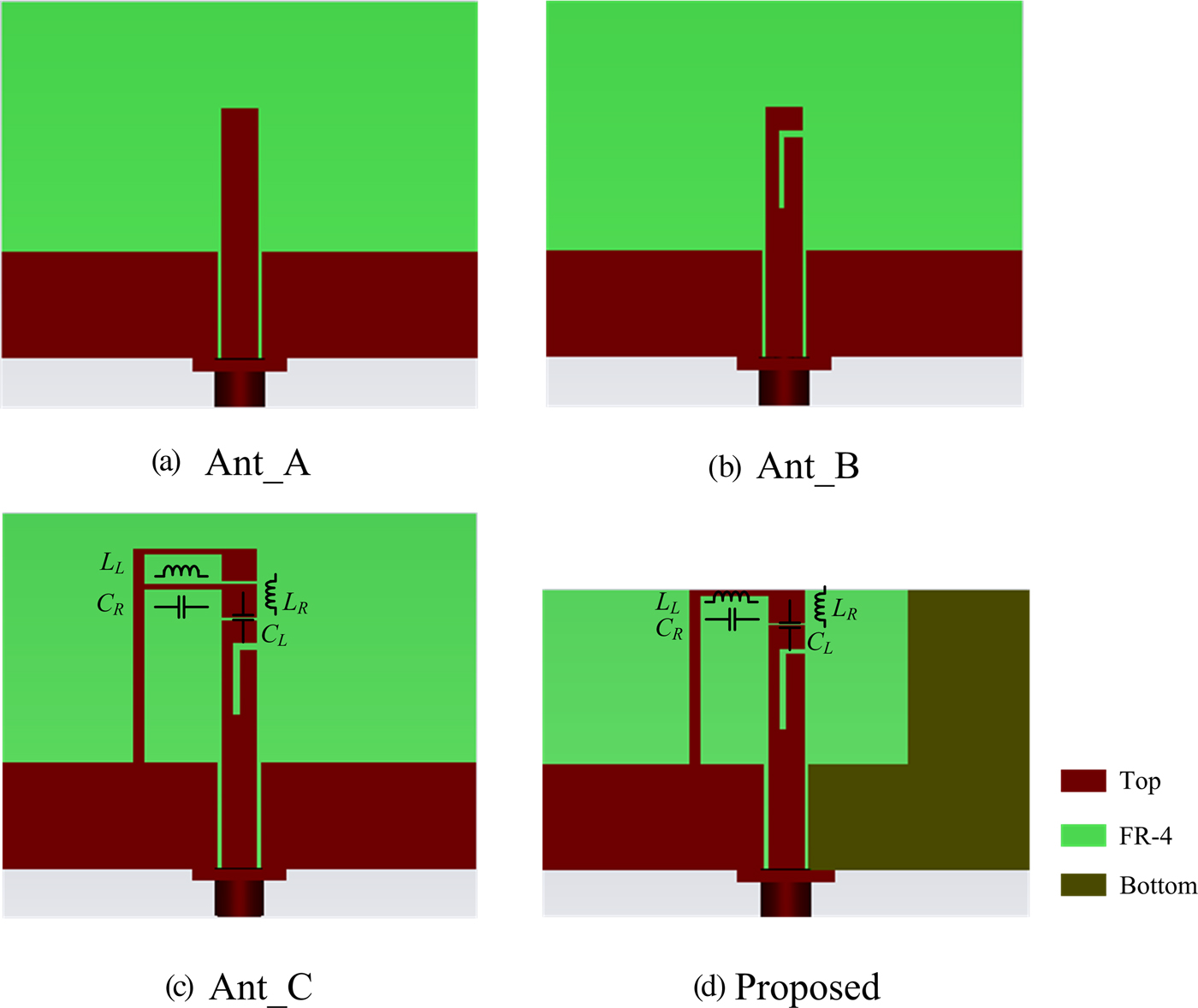
The design process of the proposed antenna goes through four steps with different configurations which are denoted in Fig. 1 as Ant_A, Ant_B, Ant_C, and the proposed antenna, respectively. The first three antennas are printed on a 1.6 mm-thick FR-4 substrate (εr = 4.3, tanδ = 0.02) with the same size of 40 mm × 30 mm and the final optimized size of the proposed antenna is 40 mm × 24 mm. The simulated reflection coefficients are carried out by HFSS and plotted in Fig. 2.

Fig. 1. Design evolution of the proposed antenna.

Fig. 2. Simulated reflection coefficients of Ant_A, Ant_B, Ant_C, and the proposed antenna.
Firstly, the design starts with a conventional CPW-fed monopole antenna as depicted in Fig. 1(a). It consists of a straight metal strip and a co-planar ground plane which are printed on top side of the substrate. For Ant_A, as shown in Fig. 2, a single band with the center frequency of 4 GHz is excited.
Then, Ant_B is designed by adding an open-ended inverted L-shaped slot to Ant_A as presented in Fig. 1(b). A dual-frequency operation at about 3.8 and 5.6 GHz can be observed as shown in Fig. 2. Since the introduction of the open-ended inverted L-shaped slot slightly increases the length of the current path, there is a frequency offset of about 0.2 GHz at the first resonance compared with Ant_A. The total length of the inverted L-shaped slot is about 8 mm which is equal to a quarter wavelength ( $\lambda _g = \lambda _0/\sqrt {(\varepsilon _r + 1)/2} $, λ 0is the free-space wavelength) at 5.6 GHz. This illustrates that the second resonant frequency of Ant_B is generated by the inverted L-shaped slot at its fundamental λ/4 resonant mode.
Third, ZOR antenna mode is established to excite two lower frequency bands in pursuit of antenna miniaturization. Empirically, two CRLH-TL unit cells are first employed on the top portion of the slotted metal strip for Ant_C as shown in Fig. 1(c). The main components of one CRLH-TL unit cell, C R, C L, L L, and L R are marked. The required capacitance can be generated by the gap between two strips and the inductance can be realized by the metal meandered stub. Obviously, two lower resonances (f 1 and f 2) at around 1.6 and 2.6 GHz are excited by loading the CRLH-TL unit cells, and the two higher resonances (f 3 and f 4) shift to 3.5 and 5.5 GHz, respectively, compared with Ant_B. In order to better analyze the working mechanism of the CRLH-TL, the electric field distribution of Ant_C is investigated as shown in Fig. 3. It is clear that the antenna operates in an n = 0 mode (in phase, ZOR) at 1.6 GHz and an n = 1 mode (180° out of phase, first-order resonator) at 2.6 GHz. So far a quad-band hybrid antenna prototype has been successfully achieved.

Fig. 3. Electric field distribution of the ZOR antenna.
Lastly, some further modifications are made to optimize the antenna performance based on Ant_C. On the one hand, for better input-impedance matching, the CPW ground plane is changed to asymmetric CPW (ACPW) ground plane and the height of the ground plane at the bottom layer is also increased. Hence, the antenna communication bandwidth has been broadened to a certain extent. On the other hand, a more compact size of 40 mm × 24 mm is ensured in the proposed antenna by cutting one CRLH-TL unit cell. This remaining one CRLH-TL unit could also successfully excite ZOR and FOR at 1.6 and 2.5 GHz and its corresponding components are marked in Fig. 1(d). Along with some other minor adjustment, similar quad-band communication performance is achieved. The simulated results of reflection coefficients showed in Fig. 2 illustrate that the proposed quad-band hybrid antenna has a broad operating bandwidth of 60 MHz (1.56–1.62 GHz), 460 MHz (2.32–2.78 GHz), 800 MHz (2.95–3.75 GHz), and 1100 MHz (5.15–6.25 GHz), fully covering the GPS, 2.4/5.2/5.8-GHz WLAN and 2.5/3.5/5.5-GHz WiMAX applications.
B) Antenna geometry and current distribution
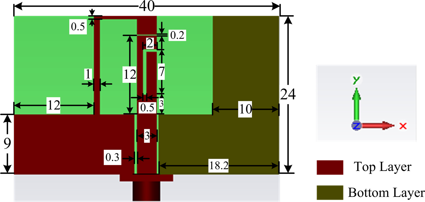
Figure 4 shows the geometry of the proposed ACPW-fed hybrid antenna. It is fabricated on a 40 mm × 24 mm × 1.6 mm FR4 substrate and composed of a slotted monopole, a CRLH-TL unit cell, and an ACPW ground plane.

Fig. 4. Geometry of the proposed antenna.
The working mechanism of the proposed antenna is investigated by means of surface current distribution analysis at 1.6, 2.5, 3.5, and 5.8 GHz as shown in Fig. 5. The surface current distributions at 1.6 and 2.5 GHz showed in Figs 5(a) and 5(b) mainly concentrate on the CRLH-TL unit cell. It indicates that the two lower resonances are mainly controlled by the CRLH-TL unit cell. The current distribution at 3.5 GHz shown in Fig. 5(c) mainly concentrates on the metal strip as a conventional monopole antenna. Figure 5(d) demonstrates that the surface current at 5.8 GHz mainly distributes around the inverted-L slot. Thus, the two higher bands are mainly determined by the design parameters of the slotted monopole antenna.
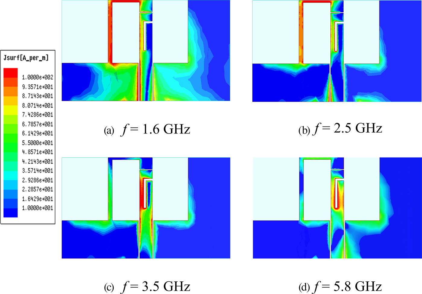
Fig. 5. Simulated surface current distributions.
C) Equivalent circuit model
The equivalent circuit model of antenna will help us better understand its electrical characteristics, and more importantly, an equivalent circuit can be integrated into the circuit-level simulation of communication systems to predict its impact and aid analysis. Since the multiband antenna contains multiple resonances across a large band, a distributed equivalent circuit model is established which consists of four parts corresponding to ZOR antenna mode, FOR antenna mode, and the dual-band monopole antenna mode, respectively. As shown in Fig. 6, the equivalent circuit models of the ZOR mode and FOR mode antennas are obtained by two CRLH-TL units; and a pair of classic series RLC circuits is employed for constructing the equivalent circuit model of the dual-band monopole antenna. The determination of circuit parameters for each part is similar. After we get the input impedance of the antenna at a single point (usually at the resonant frequency) in one band, a group of initial values can be set firstly. Then, these parameters are matched to other points in this band by using the optimization function in ADS software. The final optimized circuit parameters for the proposed hybrid antenna are listed in Table 1 and the simulated S-parameter result of the equivalent circuit using ADS is plotted in Fig. 8.

Fig. 6. Equivalent circuit model for the proposed hybrid antenna.
Table 1. Optimal equivalent circuit parameters.
III. SIMULATION AND MEASURED RESULTS
A photograph of the fabricated ACPW-fed quad-band hybrid antenna is shown in Fig. 7. The simulation results have been carried out by ANSYS HFSS and ADS (circuit model), and then verified experimentally.

Fig. 7. Photograph of the fabricated antenna: top side (left) and bottom side (right).
A) Antenna bandwidth
Simulated and measured reflection coefficients of the proposed antenna are shown in Fig. 8. Good agreement can be observed except a slight frequency shift which might be caused by the fabrication tolerance. As depicted in the figure, four distinct frequency bands are successfully excited by two different operating modes of the proposed antenna. For the two lower bands with the resonant frequencies at about 1.6 and 2.5 GHz, the proposed antenna operates as a metamaterial antenna. While for the two higher bands at 3.5 and 5.8 GHz, it operates as a monopole antenna. The measured −10 dB impedance bandwidths of the proposed antenna are 80 MHz (1.54–1.62 GHz), 390 MHz (2.37–2.76 GHz), 620 MHz (3.11–3.73 GHz), and 1090 MHz (5.06–6.15 GHz), meeting the requirement of 1.575-GHz GPS, 2.4/5.2/5.8-GHz WLAN (2.4–2.485, 5.15–5.35, and 5.725–5.825 GHz), and 2.5/3.5/5.5-GHz WiMAX (2.5–2.69, 3.3–3.7, and 5.25–5.85 GHz) applications.

Fig. 8. Simulated and measured reflection coefficients of the proposed antenna.
B) Radiation patterns
Figure 9 displays the simulated and measured normalized co- and cross-polar radiation patterns in xz- and yz-planes at 1.6, 2.5, 3.5, and 5.8 GHz. It is clear that the proposed antenna shows bi-directional radiation patterns in xz-planes and good omni-directional radiation patterns in yz-planes. However, a considerable amount of cross-polarization is found with the increased frequency, especially at 3.5 and 5.8 GHz. The relatively high cross-polarization level is mainly caused by the CRLH-TL unit and ACPW ground plane which contain both vertical and horizontal components. Nevertheless, the proposed antenna is still desirable for many applications such as mobile communication and indoor communication where the orientation of handheld devices is not fixed and the direction of arrival of the signal varies randomly. In addition, because of difficulties in enabling right-handed circularly polarization (RHCP) in small devices, GPS antennas are generally linearly polarized for the sake of design complexity, miniaturization, and cost. Therefore, the proposed antenna with a frequency band at 1.6 GHz can be employed by the GPS application.

Fig. 9. Simulated and measured radiation patterns: (a)1.6 GHz; (b) 2.5 GHz; (c) 3.5 GHz; (d) 5.8 GHz.
C) Gains and efficiency
The measured antenna gain and total radiation efficiency are presented in Fig. 10. For the 1.575-GHz GPS band, the peak gain is about 0.3 dBi. The antenna gain varies from 2.3 to 2.7 dBi for 2.4-GHz WLAN and 2.5-GHz WiMAX bands, and varies from 2.6 to 2.7 dBi for the 3.5-GHz WiMAX band. Over the frequency range of 5.15–5.85 GHz for 5.2/5.8-GHz WLAN and 5.5-GHz WiMAX applications, the gain changes from 2.4 to 3.0 dBi. The average radiation efficiencies at the four bands are about 70, 82, 83, and 85%, respectively.

Fig. 10. Peak gain and radiation efficiency.
D) Comparison results
Compared with the reported ZOR antennas [Reference Chi and Shih13–Reference Jang, Choi and Lim17], the proposed hybrid antenna exhibits outstanding quad-band characteristic, which makes it better suited for use in modern communication systems. Moreover, a comparison with other multiband antennas published recently [Reference Wang, Xing and Guo2–Reference Chen, Sim and Chen8, Reference Singh, Agarwal, Pandey and Meshram10] in terms of antenna size (λ0 is the free space wavelength at lowest resonant frequency), frequency range, bandwidth, and peak gain is presented in Table 2. The comparison results show that the proposed antenna not only achieves more compact size, but also exhibits wider bandwidth with acceptable gains.
Table 2. Performance comparison with other multiband antennas.

IV. CONCLUSION
An ACPW-fed quad-band hybrid antenna is presented by combining a slotted monopole with a CRLH-TL unit cell. In this paper, a new method to extend the bandwidth of ZOR antenna is demonstrated. Different from existing methods which mainly focuses on the optimization of ZOR antenna itself [Reference Chi and Shih13–Reference Jang, Choi and Lim17], our design offers a novel method beyond that which combines two types of antennas to achieve bandwidth extension. The proposed design makes full use of the respective advantages of ZOR antenna and monopole antenna to create a novel miniaturized, broadband and multiband antenna. Moreover, an equivalent circuit mode is also provided for better explaining the operating mechanism of the hybrid antenna. The simulated and measured results show that two operating modes are individually excited by two different parts of the proposed antenna with a relative compact size of 40 mm × 24 mm. Along with the monopole-like radiation patterns and adequate gains, the proposed antenna can be well applied to GPS/WLAN/WiMAX communication systems.
ACKNOWLEDGEMENTS
The authors would like to thank Professor K. S. Chen from the College of Information Science and Electronic Engineering, Zhejiang University, and Doctor C. Z. Hua from the School of Electrical Engineering and Computer Science, Ningbo University, for many useful discussions.
 Wang Ren received the Ph.D. degree in Electrical Engineering from the Zhejiang University, Hangzhou, China in 2008. He joined Zhejiang Gongshang University in 2008 and is currently working there as an Assistant Professor. His research interests include antenna design and microwave circuit.
 Li-Juan Zhang received her B.E. degree in Electronic Engineering from Hefei Normal University, Hefei, China in 2016. She is currently studying for the M.S. degree at the Zhejiang Gongshang University and her research interests include wideband and multiband antenna design.
 Shu-Wei Hu received his B.E. degree in Electronic Engineering from Anqing Normal University, Anqing, China in 2015. He is currently studying for the M.S. degree at the Zhejiang Gongshang University and his research interests include wideband and multiband antenna design.