


I. INTRODUCTION
In recent years, the technology of wireless communications demand compact and miniaturized uniplanar antennas of broadband or multiband operations to support wireless devices such as Radio Frequency Identification Data (RFID) applications, Global System for Mobile Communications (GSM), Industrial Scientific Medical (ISM), Wireless Local Area Network (WLAN), Wireless Fidelity (WIFI, IEEE802.11b/g), and Worldwide Interoperability for Microwave Access (WIMAX).
Therefore, the development of compact planar antennas with a large or multi-frequency operation capacities, small size, low cost, and flexibility has become a real challenge research and has derived rapidly increasing attention in modern multi-standard wireless communication systems.
A number of multiband antennas has been proposed and many techniques have been used such as etching slots on the patch [Reference Zhu and Langley1], H-shaped slot [Reference Kang, Yin, Li, Huang and Zheng2] or parasitic strip [Reference Zhao, Zhang, Song, Weng and Jiao3], defected ground plane [Reference Koo, Kim, Ryu, Kim and Yook4] and truncated ground plane with use of an L-shaped notch in lower corner [Reference Liu, Yin, Zheng, Hu and Wen5], inverted T-shaped notch in the middle, integration artificial magnetic conductor [Reference Ren, Zhang, Bao, Chen and Jiao6], implementing fractal structure [Reference Zhang, Jiao and Wang7], constructing electromagnetic bandgap structures [Reference Lee and Sun8], adding parasitic elements [Reference AbuTarboush9], feeding through coplanar waveguide [Reference Thomas and Sreenivasan10], using defected/reformed of the ground plane [Reference AbuTarboush, Nilavalan, Nasr, Al-Raweshidy, Budimir and Alexander11].
In the present paper, a new monopole coplanar waveguide (CPW)-fed multiband antenna with a simple structure for tri-band of operation for multiple wireless communications is proposed. The antenna parameters are simulated and optimized by using Computer Simulation Technology Microwave Studio (CST MWS) and the design considerations of the proposed multiband antenna are discussed and described.
II. ANTENNA DESIGN AND PERFORMANCES
The details of the geometrical configuration parameters of the final proposed multiband planar microstrip antenna are presented in Fig. 1. This antenna is implemented on a low-cost FR4 epoxy substrate with a relative permittivity ε r of 4.4, a thickness of h = 1.6 mm and a loss tangent tan of 0.025 and is fed by a CPW-fed transmission line with 50 Ω characteristic impedance. The radiator patch antenna and the feeding are implemented on the same plane of the substrate with a single side metallization. The dimensions of the designed compact antenna are 25 × 25 mm2. Several aspects were considered to optimize the final antenna design. All the design and simulated results are performed by using CST MWS and ADS “Advanced Design System”. After the optimizations of the parametric antenna geometry, the parameters of the final structure antenna are listed in Table 1.
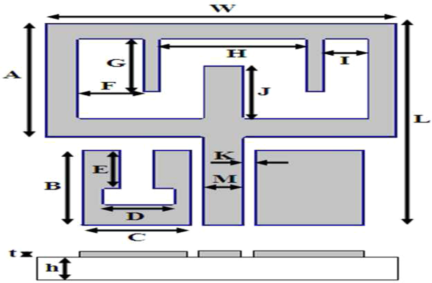
Fig. 1. Geometry of the final proposed multiband antenna.
Table 1. The optimized dimensions of the proposed antenna.

The goal of this study is to develop a new compact antenna structure for multi-frequency band to multiple incorporating operation service. The design evolution of the proposed antenna is presented in Fig. 2. The simulated return loss for the proposed antenna with different optimized dimensions of the parametric study is shown in Fig. 3. Firstly, the mono-band antenna is constructed by a rectangular slot with optimized dimensions from a radiator patch shown in Fig. 3(a) to be adapted to frequency center 2.4 GHz with a bandwidth the 130 MHz. Secondly by adding a three parallel stubs after several optimizations of the dimensions and the and the position en the level of the slot rectangular radiator patch, the dual-band antenna is obtained and is operates in these frequency bands: (2.35–2.48 GHz) and (5.3–5.8 GHz) as shown in Fig. 3(c) with a better band at 5.8 GHz due of the gap between of the stub tuning and the current distribution flow mode in radiator patch.
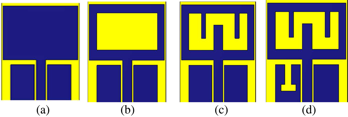
Fig. 2. Design evolution of the proposed multiband antenna.

Fig. 3. Return loss versus frequency of the proposed monopole antenna for various steps of the optimizations.
At last, the final tri-band antenna is achieved by a T-shaped slot inverted on the ground plane as shown in Fig. 3(d). Thus, we achieved the final proposed antenna ranging at multiple frequency bands: (2.35–2.48 GHz), (3.7–5.2 GHz), and (5.7–6 GHz) with a return less than −10 dB.
The current distribution of the final proposed antenna for three frequencies is shown in Fig. 4. It is observed that the surface currents distributions are concentrated around the slot of the radiator patch and CPW transmission line.

Fig. 4. Surface current distributions of the final monopole multiband antenna at (a) 2.4 GHz and (b) 5.8 GHz
Figure 5 shows the simulated 2D far-field radiation patterns of the antennas on E-plane and H-plane at 2.4 and 5.8 GHz. The simulated results show that the omnidirectionnel patterns in E-plane and bidirectionnel in H-plane for all frequency bands.

Fig. 5. Radiation pattern at 2.4 and 5.8 GHz of the final proposed multiband antenna.
III. ACHIEVEMENT AND MEASUREMENT
After the study, conception and optimization of the compact tri-band antenna by using CST, the prototype of the investigated antenna was achieved and measured to verify the performance of the results obtained from simulation. The return loss was measured by using Vectorial Network Analyzer (VNA) R&S@ZVB20 from Rohde& Schwarz, and the radiation patterns were measured in Anechoic chamber as shown in Fig. 6. The photograph of the fabricated multiband antenna is given in Fig. 7.

Fig. 6. Anechoic chamber.
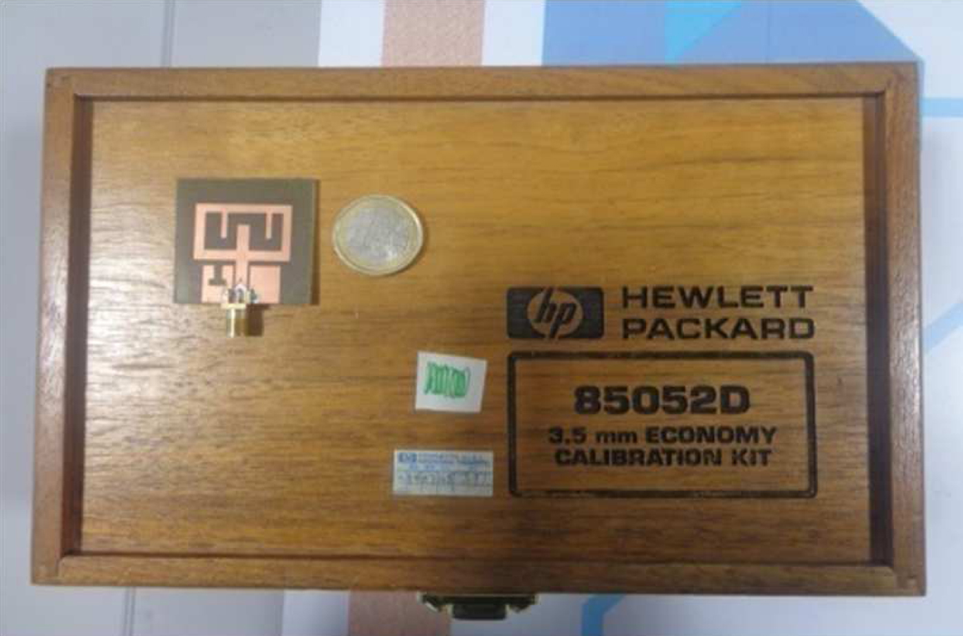
Fig. 7. Photograph of the achieved multiband antenna.
The simulated and measured return loss against frequency of final tri-band proposed antenna are given in Fig. 8. It is clearly observed that the simulation results are in agreement with measurement. This allows the validation of a new compact and miniaturized uniplanar multiband antenna structure operating from 2.4 to 2.9 GHz, 3.7 to 5.2 GHz, and 5.7 to 6 GHz, with a return loss less than −10 dB.

Fig. 8. Simulated and measured return loss versus frequency.
The measured radiation patterns at 2.4 and 5.8 GHz as shown in Fig. 9.
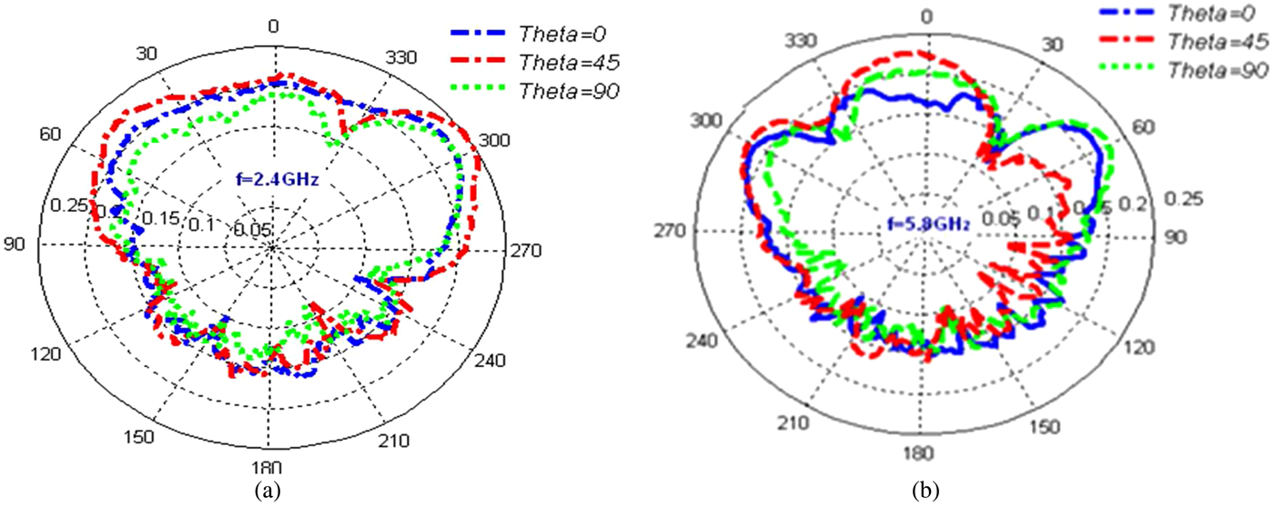
Fig. 9. Measured radiation pattern at 2.4 and 5.8 GHz.
IV. CONCLUSION
In this study, we have validated a new low-cost multiband antenna structure, suitable to operate in large frequency bands. All the conception, optimization, and simulation results are performed by using high electromagnetic simulator CST MWS. The strip lines and a slot techniques used in this work on the level of the radiator patch and the ground plane is a simple way to optimize and control the frequency band and to be adapted to the specific applications. The measured and simulation results are in agreement which validate the new compact antenna structure ranging from 2.4 to 2.9 GHz, 3.7 to 5.2 GHz, and 5.7 to 6 GHz operating in specific applications of ISM band, WLAN, WIMAX, and RFID.
ACKNOWLEDGEMENTS
We thank Mr Mohamed Latrach Professor in ESEO, Engineering Institute in Angers, France and Mr. Angel Mediavilla Sanchez Professor in the University of Cantabria for allowing us to use all the equipments and softwares available in his laboratory.
 R. Dakir was born in 16 January 1982. He received the Ph.D. degree in FST University Hassan 1st Settat Morocco. He is involved in the design of hybrid, monolithic active, and passive microwave electronic circuits.
 J. Zbitou was born in Fes, Morocco, in June1976. He received the Ph.D. degree in Electronics from the University of Nantes, Nantes, France, in 2005. He is currently a Professor of Electronics in FPK University Hassan 1st Settat Morocco. He is involved in the design of hybrid, monolithic active, and passive microwave electronic circuits.
 A. Mouhsen was born in May 1960. He received the Ph.D. degree in Electronics from the University of Bordeaux I, France. He is currently a Professor of Electronics in FSTS University Hassan 1st Settat Morocco. He is involved in the design of hybrid, active and passive microwave electronic circuits, and digital systems.
 A. Tribak was born in Larache, Morocco, in 1981. He received the M.Sc. degree in Physics from Abdelmalek Essaadi University, Tétouan, Morocco, in 2006. He received a Master degree in Communications Engineering from the University of Cantabria, Santander, Spain, in 2008, and received the Ph.D. degree in Telecommunication in 2011, from the University of Cantabria, Santander, Spain. Since 2006 to 2011, he has been with the Department of Communications Engineering, University of Cantabria. Since 2011 he is a Professor in the National Institute of Poste and Telecommunication, Rabat, Morocco. His main areas of activities are microwave circuits and systems; antenna feed subsystems for satellite, and radio-astronomy applications.
 M. Latrach was born in Douar Ksiba, Sless, Morocco, in 1958. He received the Ph.D. degree in Electronics from the University of Limoges, Limoges, France, in 1990. He is currently a Professor of microwave engineering with the Ecole Suprieure d'Electronique de l'Ouest (ESEO), Angers, France, where his research involves RF and microwaves. His field of interest is the design of hybrid, monolithic active, and passive microwave circuits, metamaterials, LH materials, antennas and their applications in wireless communications, and wireless power transmission.
 A. M. Sanchez was born in Santander, Spain, in 1955. He graduated in 1978 and received the Doctor of Physics (Electronic) degree with honors in 1983, both from the University of Cantabria, Santander, Spain. From 1980 to 1983 he was Ingenieur Stagiere at THOMSON-CSF, France. He is currently head of the Communications Engineering Department at the University of Cantabria. He has a wide experience in the analysis and optimization of nonlinear microwave active devices. His research interests are nonlinear MESFET/HEMT and HBT device modeling with special application to the large signal computer design and new waveguide structures for antenna feed systems.


