


Introduction
The microstrip antenna is considered an important component in modern ultra wideband (UWB) systems; recently researchers have developed many different antenna designs for UWB applications with wide impedance bandwidth, reasonable gain, linear phase, and stable radiation characteristics across the entire UWB frequency range. These developments in modern wireless communication systems have imposed additional challenges to produce new designs that are miniaturized and have a good broadband performance [Reference Balanis1, Reference Prasanna and Behera2].
In multiple-input–multiple-output (MIMO) systems, multiple antenna elements are required at both receiver and transmitter side [Reference Zhang and Pedersen3]. As a result, the design of two or more antennae on small mobile terminals for the MIMO systems is more challenging compared with the design of the conventional single antenna [Reference Li, Feresidis, Mavridou and Hall4]. However, installing multiple antenna elements in the small space available in portable devices will inevitably cause severe mutual coupling and significantly degrade the diversity performance. Thus one of the main challenges in employing MIMO systems in mobile devices is the design of small antennas with low mutual coupling level [Reference Li, Li, Liu and Jiang5]. With the rapid expansion of wireless MIMO communication systems, the demand for low profile, wide bandwidth, and high isolation between antenna elements has increased to maintain a good diversity performance. High isolation (low mutual coupling level) between the adjacent antenna elements is one of the essential requirements for any recent MIMO antenna implementation [Reference Li, Feresidis, Mavridou and Hall4]. Mutual coupling between closely spaced antennas is caused by radiation emission (RE) through the electromagnetic coupling and conduction emission (CE) through a common conductor such as the ground plane [Reference Balanis1].
When a multiple-element antenna embeds into the small mobile terminal, it should be compact (low profile) as much as possible. Additional requirements should also be met, e.g., lowest mutual coupling (higher isolation between antennas) and robustness while maintaining the compactness with acceptable diversity performance for multiple antennas [Reference Zhang and Pedersen3]. Therefore, in designing the antenna for the mobile terminal, it is important to balance the trade-off between compactness and performance [Reference Prasanna and Behera2].
In recent years, several techniques have been employed to achieve these objectives [Reference Li, Li, Liu and Jiang5]. Among the main techniques that has been extensively studied and discussed in the literature for the mutual coupling reduction are: neutralization line (NL) method [Reference Zhang and Pedersen3, Reference Chebihi, Luxey, Diallo, Le Thuc and Staraj6], insertion of miniaturized double layer electromagnetic band gap (EBG) structure [Reference Li, Feresidis, Mavridou and Hall4], defected ground structure (DGS) [Reference Li, Li, Liu and Jiang5, Reference Chiu, Cheng, Murch and Rowell7], implementation of separated ground plane [Reference Jusoh, Jamlos, Kamarudin and Malek8], spatial and angular variations techniques [Reference Lin and Huang9–Reference Wong, Su and Kuo13], parasitic elements were also inserted between the elements to improve the isolation [Reference Li, Du and Gong14], and inserting a stub structure on the shared ground plane [Reference Liu, Cheung and Yuk15–Reference Hong, Chung, Lee, Jung, Lee and Choi18], etc.
In this paper, a new monopole MIMO antenna with high isolation and a compact size has been designed and developed for UWB application. The proposed UWB antenna exploits the approach of using a compact wideband planar decoupling structure in between to augment the isolation level. The proposed UWB–MIMO antenna shows good impedance characteristics in the frequency band range of 3.1–10.6 GHz with excellent isolation characteristics, the antennas are simulated with commercially available HFSS software version 17.0 which is mainly based on finite element methods.
The remainder of the paper is organized as follows: the section “Antenna design” briefly describes the design procedure of the proposed UWB–MIMO antenna. The section “Performance of the multiple antennae” presents some simulation performance results and the significance of the proposed wideband decoupling structure. The section “Fabrication and experimental demonstration” outlines an experimental validation and present some measurements results. In the section “Comparison with other work” a comparison with other previous works is carried out and summarized. Finally, some conclusive comments and further scope are expressed in the section “Conclusions”.
Antenna design
UWB–MIMO antenna configuration
In microstrip antenna array designs, circular and semi-circular monopole antennas have more impedance bandwidth compared with rectangular, triangular, square, and hexagonal monopole antennas [Reference Prasanna and Behera2]. The designed and fabricated UWB–MIMO antennas without the proposed wideband decoupling structure are shown in Fig. 1.

Fig. 1. A proposed UWB–MIMO antenna without the decoupling structure. (a) Schematic antenna layout (top view), (b) a prototype of the fabricated antenna (top and back view).
The array consists of two symmetrical circular-shaped monopole radiating elements [Reference Choi, Park, Kim and Park19] denoted as Ant-1- and Ant-2-, which are located on the same sides of the common FR4 substrate with dielectric constant equals to ε r = 4.4 (loss tangent = 0.018) and thickness h = 1.6 mm [Reference Choi, Park, Kim and Park19].
The selection of the circular disc antenna can be justified by its good performance, compact size, and ease of integration [Reference Najam, Duroc and Tedjni16]. The microstrip antenna elements working at UWB frequency range (f = 3.1–10.6 GHz) are placed collinearly along the x-axis, and the spacing between antenna array elements is approximately equal to 0.35λ 0 of the lowest frequency band (measured from element center to center).
As mobile terminals such as handsets and PDAs have become smaller, the design of smaller antenna elements are required, thus, the dimensions of the monopoles should be further reduced. The antenna is formed by a metallic disc of radius R = 12 mm, and it has a partial ground plane printed on the back side of the substrate with a ground length L g = 93 mm, and a ground width W g = 10.6 mm.
The total dimensions of UWB antennas are 93 × 47 × 1.6 mm3 (correspond approximately 0.95 λ 0 × 0.49 λ 0 × 0.016 λ 0) to be suitable for most mobile printed circuit boards (PCB), other antenna dimensions obtained after optimization process are given in Table 1.
The distance (g) between the ground plane and the antenna radiating element effects the impedance bandwidth and hence the gap distance has been optimized here at g = 0.5 mm. Moreover, for getting a better impedance matching (particularly in the higher frequencies), two small rectangular slots (denoted by S 1 and S 2) of compact dimensions 1.6 mm × 6 mm were introduced on the common ground plane to enhance the impedance bandwidth. These slots are cut on the upper edge of the ground plane underneath each feed line. Finally, the radiating circular patch is made up of a very thin copper sheet with a thickness of 0.1 mm.
Table 1. Detailed dimensions of the UWB antenna

Multiple antennas and decoupling structure for coupling reduction
The layout of the proposed wideband decoupling structure is illustrated in Fig. 2(a). The proposed structure composes of modified metallic patch like T on the upper side with optimized dimensions L 2 = 9 mm × W 1 = 36 mm, another smaller metallic patch like inverse T on the lower side with optimized dimensions L 3 = 6 mm × W 2 = 17 mm are joint and subtracted by four half-circular slots (dual half-circular in the upper side and another dual smaller half-circular on the lower side) to form a parasitic strip that has been applied as a compact wideband planar decoupling structure between UWB antennas. The structure is symmetrical along the Z-axis from the center. The proposed wideband decoupling structure has longer current paths that it could work in the low-frequency range.

Fig. 2. (a) Detailed layout of the proposed decoupling structure, (b) Schematic UWB–MIMO antenna with decoupling structure (front and rear view), (c) A prototype of the fabricated diversity antenna (top and back view).
The parameters given in Fig. 2(a) were optimized using the simulation software (HFSS) and the detailed optimum dimensions of the proposed decoupling structure used in this work are given in Table 2.
Table 2. Detailed dimensions (in mm) of the proposed structure

The proposed wideband planar decoupling structure was then inserted between the dual-monopole antenna elements to reduce mutual coupling, it will provide additional coupling paths and reduce directly induced coupling currents in the radiating elements (as presented in the next section).
Performance of the multiple antennae
Simulated scattering parameters
The return loss (reflection coefficient) and the transmission loss (mutual coupling) for the dual antenna array elements without and with the proposed decoupling structure are plotted in Figs 3(a) and 3(b), respectively.

Fig. 3. The simulated scattering parameters of proposed UWB–MIMO antenna without (dashed line-black color) and with decoupling structure (solid line-red color). (a) Reflection coefficient (S 11), and (b) transmission coefficient (S 21).
Figure 3(a) illustrates the reflection coefficient performance; it was observed that the UWB antennas in both cases (without and with structure) have a wide broadband bandwidth ranging from 3 to 11 GHz (for S 11 < −10 dB). Thus the array antenna satisfies the impedance matching requirement for the entire UWB range specified by the Federal Communications Commission. All these analyses were conducted with one antenna element transmitting and the other antenna terminated with 50 Ω load.
The mutual coupling between antenna elements can be determined from scattering parameters; S 21 or S 12. The simulated mutual coupling is shown in Fig. 3(b).
An isolation of <−31 dB has been achieved through the entire UWB band (more than 12 dB improvement over the reference antenna). This result satisfies the required condition for mutual coupling between the antennas for proper operation of the MIMO system in the UWB frequency range.
Isolation mechanism and working with the various decoupling structures
The direct mutual coupling between two antenna elements can be canceled out by properly adding an extra indirect coupling path. A proper design aims at creating an indirect signal coming via the extra coupling path that opposes the signal going directly from element to element. If the two amplitudes are comparable and out of phase, the two signals add up destructively, and the mutual interaction is considerably reduced. An extra requirement is that the inserted decoupling structure should not significantly degrade the radiation properties. In the approach followed here, by placing and adding a non-resonating and parasitic decoupling structure between antennas, extra active coupling paths can be created. The coupled radiation introduces induced currents on the neighboring antenna. The proposed wideband decoupling structure can also capture the near coupling fields and converts them in surface currents to be shorted with the ground plane and such that multiple coupling paths reduce the direct strong coupling between ports and hence reducing the mutual coupling. In this work, the dimensions of the proposed decoupling structure were optimized to obtain a maximum surface currents pickup strategy. The surface currents analyses are presented in the next section.
To further inspect the performance of the MIMO antenna and investigate the best decoupling structure arrangement to be utilized in the UWB–MIMO antenna configuration, five different geometrical models are given in Fig. 4, and individual simulated S 21 parameter variations plotted for these five models is presented in Fig. 5.

Fig. 4. UWB–MIMO antenna elements with different geometrical models. (a) Without decoupling structure (Model I), (b) with a center slot on the ground (Model II), (c) with conventional rectangular-shaped decoupling structure (Model III), (d) with T-shaped decoupling structure (Model IV), and (e) with proposed wideband planar decoupling structure (Model V).

Fig. 5. Simulated S 21 parameters for different geometrical models of UWB–MIMO antenna.
However, inserting both a center slot in common ground (Model II) and a conventional rectangular structure (Model III), as given in Figs 4(b) and 4(c); respectively, help to improve isolation between the antenna array but not for the entire UWB range, only a real enhancement, S 21 ≤ −24 dB can be seen in the higher frequencies range. To further increase the isolation between antennas especially in lower frequencies range of the UWB operation; a T-shaped structure (Model IV) has been presented in the middle of the substrate as illustrated in Fig. 4(d), thus; the S 21 parameter here has some good values (below −28 dB) toward lower UWB frequencies but remains with high coupling as it is expected to be in higher frequencies (> 5.5 GHz). Finally, by introducing the proposed wideband decoupling structure (Model V) as seen in Fig. 4(e), an excellent isolation of <−31 dB (more than 12 dB improvement over the reference) has been achieved through the entire UWB band, and hence this case can satisfy the requirements of an applicable UWB operation with the highest isolation.
Simulated radiation patterns, gain, and radiation efficiency
The orientation of the proposed antenna with respect to the coordinate system is shown in Fig. 1. This section presents the study performed on the effect of far-field radiation patterns as a comparison between both cases (with and without inserting the proposed wideband decoupling structure).
The simulated far-field radiation patterns are normalized with respect to the realized gain on the major principal planes (Y–Z and X–Y planes) in both prototypes, without and with wideband decoupling structure, are shown in Fig. 6.

Fig. 6. The simulated 2D radiation patterns without and with the proposed decoupling structure: (a1) y–z plane, and (a2) x–y plane at 4 GHz; (b1) y–z plane, and (b2) x–y plane at 6 GHz; and (c1) y–z plane, and (c2) x–y plane at 8 GHz, respectively, with port 1 excited (solid line: co-pol, dashed line: cross-pol, black color: with, and red color: without).
In general, we can see that the overall radiation patterns are relatively stable across the different UWB frequencies. Still, nearly omnidirectional patterns are obtained at various frequencies (4, 6, and 8 GHz) before and after inserting the wideband decoupling structure, no significant degradation of radiation patterns are noticed between the two designs (with and without decoupling structure) in Y–Z and X–Y planes.
However, an enhancement in radiation characteristics helps to improve the peak gain of the antenna, the gain variation without decoupling structure is 1.4 dBi, however, this difference reduces to <0.5 dBi with a peak gain of 3.5 dBi at a frequency (9 GHz), when the proposed wideband decoupling structure is inserted, which makes it more consistent over the radiating bandwidth. Since the isolation is achieved by using a wideband parasitic decoupling structure, there is the possibility of a reduction in radiation efficiency.
The antenna radiation efficiency is simulated with and without wideband decoupling structure. The comparison is provided in Fig. 7.

Fig. 7. Simulated antenna gain variation (left side) and radiation efficiencies (right side) over the radiating band of the proposed UWB–MIMO antenna.
The radiation efficiency of UWB antennas remains above 70% in the complete frequency band. The radiation efficiency only varies by <10% in the whole band which certifies that the parasitic wideband decoupling structure does not have any notable effect on radiation characteristics.
The radiation efficiency at the lower UWB frequencies is better for diversity antenna with decoupling structure which indicates that the wideband decoupling structure reduces the return loss at lower frequencies. At the upper UWB frequencies, the radiation efficiency with decoupling structure is less than an antenna without wideband decoupling structure which indicates an increase in mismatch loss at higher frequencies.
Simulated surface currents distribution
To further elaborate the effectiveness of the insertion of the decoupling structure, the degree of isolation in the proposed UWB antenna can be observed by presenting surface currents distribution.
Figures 8(a)–8(c) show the currents distribution with and without the wideband decoupling structure at three different frequencies (4, 6, and 8 GHz) when Ant-1- is excited, while Ant-2- is terminated with a load impedance of 50 Ω. The effects of the proposed wideband decoupling structure on the currents distribution can clearly be noticed by comparing with those without structure.

Fig. 8. Simulation of surface currents distribution on the proposed antenna array without structure (left side) and with decoupling structure (right side), when the first antenna is excited and the second antenna is terminated with a 50 load at a frequency: (a) 4 GHz, (b) 6 GHz, (c) 8 GHz.
The surface currents are absorbed by wideband decoupling structure, and thus it ameliorates the port isolation between two UWB monopoles.
It is observed from Figs 8(a)–8(c) that less amount of surface currents are induced in the second UWB antenna because most of the antenna's direct coupling field is concentrated in the planar wideband decoupling structure; this shows the creation of additional current paths between the two radiating elements and prevents most of the induced currents to be transferred toward the second antenna. The effect is the same when Ant-2- was excited while Ant-1- was terminated with 50 Ω load.
Diversity performance
The envelope correlation coefficient (ECC) between antenna elements is another crucial parameter and one of the most important parameters as it indicates and evaluates the MIMO/diversity performance because it is directly related with the antenna scattering parameters and may significantly degrade diversity system performance.
For dual (2 × 2) MIMO antenna system, the ECC equation using the scattering parameters is given by [Reference Byun, Jo and Lee20].
 $$\rho _{12} = \displaystyle{{{\left \vert {S^{^\ast}_{11} S_{21} - \; S^{^\ast}_{12} S_{22}} \right \vert} ^2} \over {\left( {1 - {\left \vert {S_{11}} \right \vert} ^2 - {\left \vert {S_{21}} \right \vert} ^2} \right)\left( {1 - {\left \vert {S_{22}} \right \vert} ^2 - {\left \vert {S_{12}} \right \vert} ^2} \right)}}\;. $$
In this work, ECC (ρ 12) can be calculated using (1) under some assumptions: in ideal and uniform propagation multipath environment, antenna system is lossless and one of the antenna elements is excited separately while keeping the other antennas matched terminated.
In Fig. 9, the ECC for the antenna elements with and without the proposed wideband decoupling structure is shown against the working frequency. From the simulated results, the maximum ECC of −29 dB over the UWB frequency range of antenna elements with the proposed wideband decoupling structure is smaller than that of the array elements without structure.

Fig. 9. Simulated envelope correlation coefficient of the proposed UWB–MIMO antenna without (dashed line-red color) and with wideband decoupling structure (solid line-black color).
This observation indicates better behavior and a good diversity performance of the antenna system will be achieved by using the proposed wideband planar decoupling structure.
Fabrication and experimental demonstration
The proposed UWB antennas were fabricated by using the PCB material of inexpensive FR4 substrate having a thickness of 1.6 mm, dielectric permittivity constant of 4.4 (with a loss tangent of 0.017). The microstrip lines were fed through 50 Ω Sub Miniature version A (SMA). Photographs of fabricated UWB–MIMO antennas without and with wideband decoupling structure are illustrated before in Figs 1(b) and 2(c), respectively.
Simulated and measured scattering parameters
To validate the simulation results, the proposed UWB antenna has been fabricated, tested, measured, and then compared with simulated results.
The performance of the UWB–MIMO antenna has been verified through a measurement performed by means of Agilent Technologies N5230A PNA–L RF network vector analyzer inside Brunel University London.
The measured and simulated scattering parameter plots (return loss and transmission loss) are presented in Figs 10(a) and 10(b), respectively.
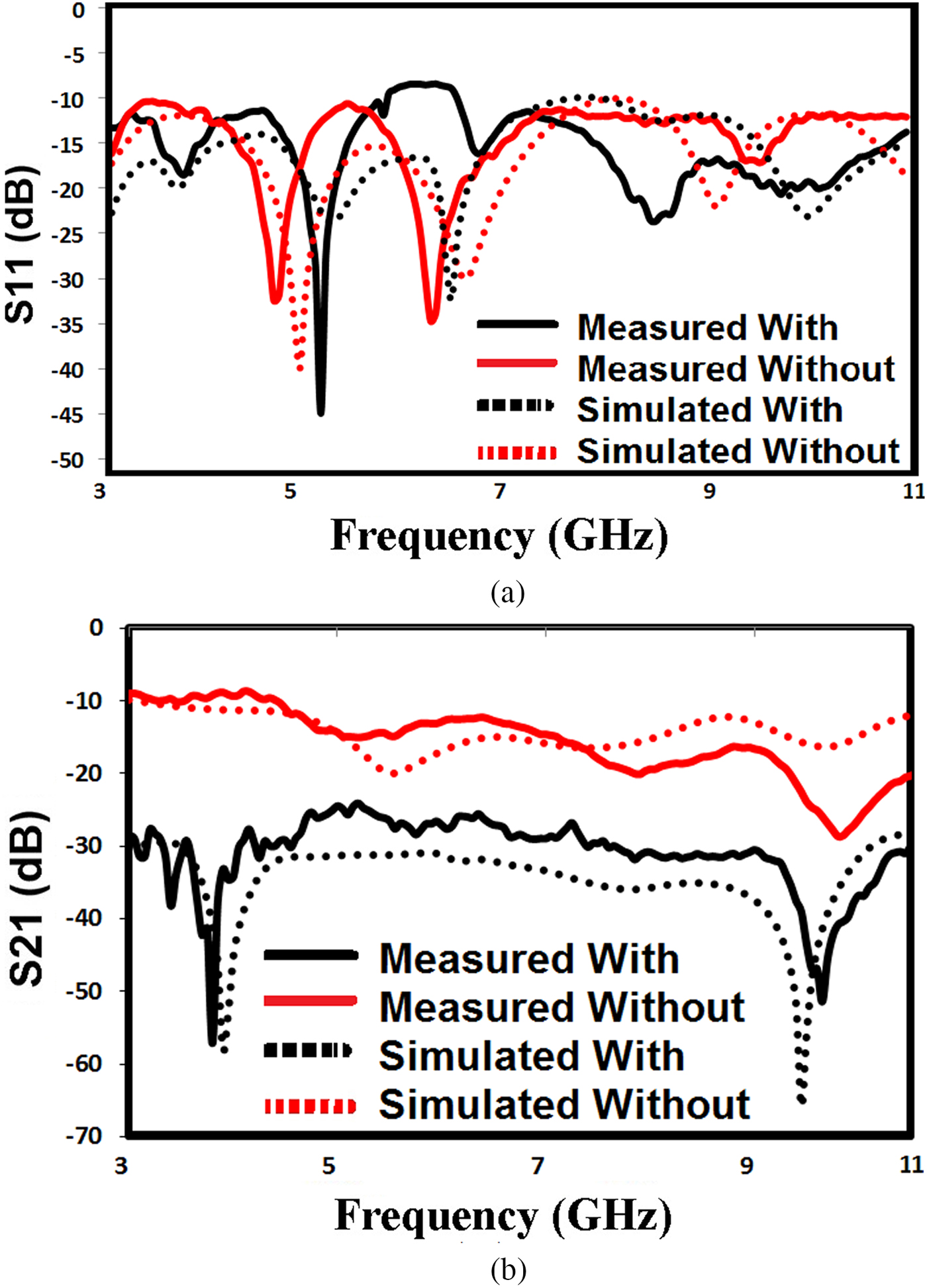
Fig. 10. Comparison of simulated and measured scattering parameters without and with a wideband decoupling structure. (a) Reflection coefficient (S 11) and (b) transmission coefficient (S 21).
Figure 10(a) shows the measured and simulated return loss of the impedance bandwidth (S 11 < −10 dB) comparatively between the dual UWB antennas with and without the proposed wideband decoupling structure.
It is observed that the proposed antennas has a wide measured bandwidth 7.5 GHz and covers the whole UWB ranging 3.1–10.6 GHz with a return loss better than −10 dB that satisfy the requirements of UWB operation.
A reasonably good agreement can be noticed between the measured and simulated plots although a slight difference between these results can be noticed.
That may be attributed to factors such as an inaccuracy in the fabrication process, variation in the quality of the substrate, and mismatch effect of SMA connectors.
In all these measurements, one port is excited and the other terminated by the standard 50 Ω loads.
Figure 10(b) shows the measured and simulated mutual coupling comparatively between the dual UWB antennas with and without the proposed wideband decoupling structure.
The prototyped MIMO antenna has wide frequency range covers from 3 to 11 GHz with the measured isolation <−27 dB. These results agree well with the simulated results obtained before as shown previously in Fig. 3.
A slight deviation can be attributed to the fabrication tolerances. From this experimental verification, it can be concluded that the proposed wideband decoupling structure can reduce the mutual coupling between antenna array elements.
Simulated and measured radiation patterns
The radiation patterns of the proposed UWB–MIMO antenna were measured in an anechoic chamber of the University of Greenwich at various frequencies (4, 6, and 8 GHz). The measured and simulated far-field radiation patterns are normalized with respect to the realized gain without and with the proposed wideband decoupling structure as presented in Figs 11 and 12, respectively:
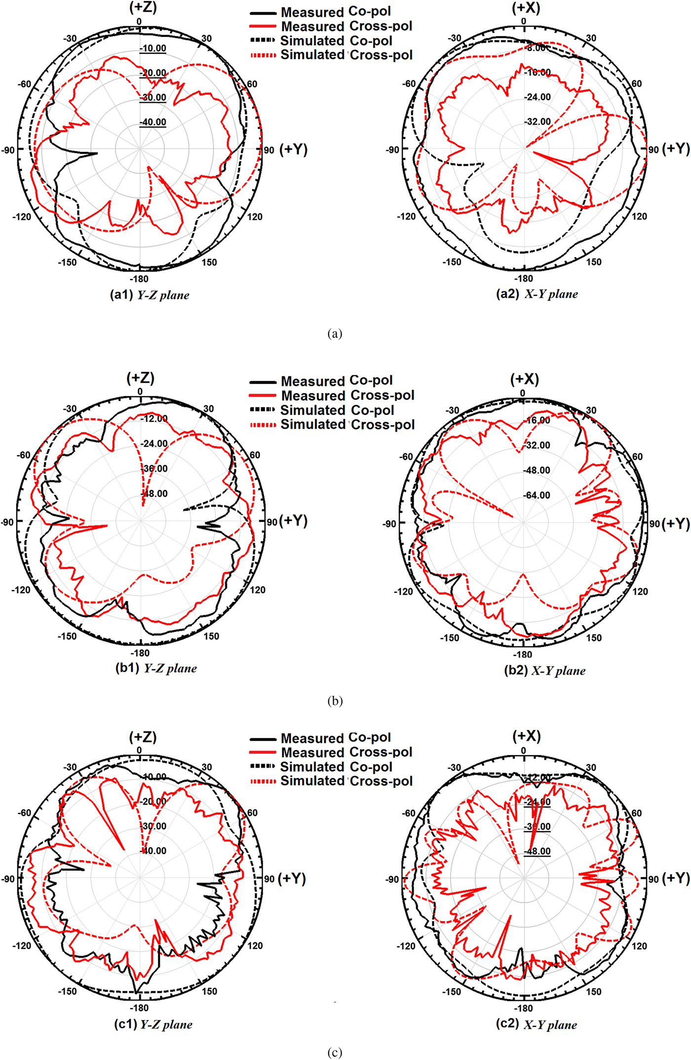
Fig. 11. Measured versus simulated radiation patterns (normalized) without the proposed decoupling structure: (a1) y–z plane, and (a2) x–y plane at 4 GHz; (b1) y–z plane, and (b2) x–y plane at 6 GHz; and (c1) y–z plane, and (c2) x–y plane at 8 GHz, respectively, with port 1 excited (solid line: measured, broken line: simulated, black color: co-pol, and red color: cross-pol).

Fig. 12. Measured versus simulated radiation patterns (normalized) with the proposed decoupling structure: (a1) y–z plane, and (a2) x–y plane at 4 GHz; (b1) y–z plane, and (b2) x–y plane at 6 GHz; and (c1) y–z plane, and (c2) x–y plane at 8 GHz, respectively, with port 1 excited (solid line: measured, broken line: simulated, black color: co-pol, and red color: cross-pol).
During the measurement, one of the input ports was excited, and the other was terminated with a 50 Ω load.
In general, no significant difference is observed between the different co-polarization and cross-polarization patterns of the measured and the simulated results.
The radiation patterns are good omnidirectional in the major planes (Y–Z and X–Y planes). However, some nulls appear after inserting the proposed wideband decoupling structure, especially, in the measured cross-polarized.
Moreover, there are some slight discrepancies between the measured and the simulated results in the different frequency band of interest, which are probably due to the effect of the SMA connectors and implementation imperfections.
Comparison with other work
Table 3 presents a summarized comparison of our proposed UWB–MIMO antenna against other array works previously reported and recently published in the literature. The UWB antennas are tabulated in terms of various criteria such as bandwidth, mutual coupling level, geometric size and complexity, and isolation technique.
Table 3. Comparison with previous works of UWB–MIMO antenna designs

Therefore the proposed UWB–MIMO antenna array has some outstanding characteristics because of the compact size, geometric simplicity, broad bandwidth, low correlation, and good diversity performance.
All these results demonstrate that the proposed MIMO antenna configuration is a good candidate for some UWB portable devices.
Conclusions
A new monopole MIMO antenna with high isolation and a compact size of 93 × 47 × 1.6 mm3 has been designed and developed for UWB application. The prototype of the antenna was printed on the inexpensive FR4 substrate. A simple but highly efficient isolation technique is proposed. The effectiveness of the proposed wideband decoupling structure has been shown to be useful in achieving compactness, and better isolation of <−31 dB is obtained through the entire UWB frequency range for an antenna spacing <0.35 λ 0 of the lowest frequency. The simulations agree well with the measurements including both scattering parameters and far-field radiation pattern properties. Moreover, analysis results (theoretically and practically) show that the proposed UWB–MIMO antenna guarantees an entire UWB bandwidth with high isolation and keeps nearly omnidirectional radiation performance successfully. Finally, the antenna has been compared in detail with other UWB designs in terms of bandwidth, mutual coupling level, geometric size, and an implementation complexity. All results indicate that our proposed antenna array has more advantages than other suggestions in points of these criteria and it can be capable of employing in some portable devices such as mobile handsets or laptops using UWB technology combined with MIMO techniques.
 Alaa H. Radhi was born in 1981. He received the B.Sc. degree (Hons.) in electronics and communication engineering from the University of Technology, Iraq, in 2004, and an M.Sc. degree in wireless communication systems (with merit) from Brunel University London, London, UK, in 2008. He worked in many Telecommunication and broadband companies (private and governmental sectors). Since 2009; he worked as a Senior Engineer at both Ministry of Communications (MOC) and Iraq Telecommunication and Post Company (ITPC) in Iraq. He is currently working toward a Ph.D. degree in communication engineering at Wireless Network Communications Centre (WNCC)/Brunel University London, London, UK, since January 2015. His current research interests include microstrip MIMO/diversity antennas design and optimization specifically on mutual coupling reduction and isolation enhancement in different wireless applications. During his study, he participated in many international conferences sponsored by well-known organizations such as the IEEE and IET.
 Rajagopal Nilavalan received the B.Sc. Eng. degree in electrical and electronics engineering from the University of Peradeniya, Sri Lanka, in 1995 and a Ph.D. degree in radio frequency systems from the University of Bristol, Bristol, UK, in 2001. From 1999 to 2005, he was a Researcher at the Centre for Communications Research (CCR) at the University of Bristol, UK. Since 2005, he has been with the Department of Electronics and Computer Engineering, Brunel University, London, UK, he is currently a Senior Lecturer in wireless communications. His main research interests include antennas and propagation, microwave circuit designs, numerical electromagnetic modeling, and wireless communication systems. He has published over 120 papers and articles in journals and international conferences in his research area. Dr. Nilavalan was a member of the European commission, Network of Excellence on Antennas from 2002 to 2005 and a member of the IET.
 Yi Wang received the B.Sc. degree in physics and an M.Sc. degree in condensed matter physics from the University of Science and Technology, Beijing, China, in 1998 and 2001, respectively, and a Ph.D. degree in electronic and electrical engineering from The University of Birmingham, in 2005. In 2011, he became a Senior Lecturer at the University of Greenwich, UK. His current research interests include millimetre-wave/terahertz devices for metrology, communications and sensors, microwave circuits based on multi-port filtering networks, and antennas.
 Hamed S. Al-Raweshidy received the Ph.D. degree from the University of Strathclyde, Glasgow, UK, in 1991. He is currently the Director of the Wireless Networks and Communications Centre, and the Director of PG studies with the Department of ECE, Brunel University London, UK. He has authored over 400 papers in International Journals and referred conferences. His current research area is 5G and beyond such as C-RAN, SDN, IoT, M2M, and radio over fiber. He is the Editor of the first book in Radio over Fibre Technologies for Mobile Communications Networks. He acts as a Consultant and involved in projects with several companies and operators such as Vodafone (UK), Ericsson (Sweden), Andrew (USA), NEC (Japan), Nokia (Finland), Siemens (Germany), Franc Telecom (France), Thales (UK and France), and Tekmar (Italy).
 Amira A. Eltokhy was born in Egypt, in 1989. She finished her B.Sc and M.Sc. degrees in Egypt. She is currently working toward a Ph.D. degree at the Department of Engineering Science, University of Greenwich, Chatham Maritime campus, Kent, UK. Her current research interest includes radio communications, wave propagation, and integrated filtering microstrip antennas design.
 Nur Ab Aziz received her MEng in electronic and electrical engineering from the Brunel University in 2013, and is currently pursuing her Ph.D. degree in communication engineering at Brunel University London, UK, since August 2014. Her current research interests include smart antenna design specifically on designing pattern reconfigurable antenna.


