


Introduction
With the escalation in demand for high data rate communication systems along with commercialization of the fourth generation (4G) networks, there is an emergence of research related to ongoing fifth generation (5G) technologies. The initiatives have been taken and programs launched by a number of organizations worldwide that aim at the key technologies for 5G. There is an ongoing study that suggests the major requirements for 5G include high spectral efficiency (SE) and energy efficiency (EE), low latency, and greater number of node connections. The SE in the available spectrum is considered to be the prioritized design constraint for wireless networks considering the increasing capacity demand. There has been an improvement of data rates from Kilo-bits per second (Kbps) in 2G to Giga-bits per second (Gbps) toward 5G. There is an overall 70% of the total power consumed by the radio access networks. The improvement in the EE is lagging with the overall growth of data traffic in the networks. There is a need of reliable wireless networks for future generations that will be both spectrally efficient as well as in terms of energy. Thus the optimization of SE and EE together is very critical related to 5G technology research [Reference Chih-Lin, Rowell, Han, Xu, Li and Pan1].
There is a target of deploying 5G in 2020 and beyond with regard to International Telecommunications Union (ITU) radio communication standards sector. One of the most important issues related to 5G deployment is the availability of spectrum required for 5G which could be managed and used efficiently. In view of this, the institutions for 5G research are paying greater attention on the available spectrum to be utilized for 5G deployment. Some of the global institutions include IMT-2020 promotion group of China (IMT-2020 PG), Europe's EU-FP7-METIS project, etc. [Reference Wang, Li, Ding, Miao, Li and Wang2]. Some of the requirements for specifying the 5G technology include frequency allocation bands, data rates, density of connectivity and reliability, spectral density, latency, and mobility as depicted from Fig. 1 [Reference Huang3–Reference Series5].
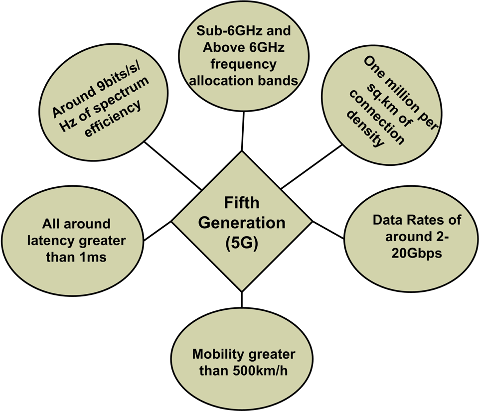
Fig. 1. Specification requirements for the 5G technology.
The emerging potential frequency bands include the bands above and below 6 GHz. 5G is able to operate in millimeter-wave frequency bands in addition to lower frequency bands of below 6 GHz. In comparison to 4G with the delivering data rates of around 20 Gbps (maximum) and the average of more than 100 Mbps (minimum), the 5G is considered to be very fast. The lower latencies in 5G are achieved by using low density parity check coding as the error correcting code in the forward direction. The maximum speed at the mobile station which refers to the mobility is around 500 kilometers per hour in case of 5G. In 5G, the capacity of the systems is increased by utilizing beam division multiple access and filters bank multicarrier thus handling more number of users at a particular instant of time. In addition to the higher data rates of 2–20 Gbps, the 5G provides 1 million/km2 of connection densities and the reliability with the outrage link of approximately 0.999 [Reference Mitra and Agrawal6]. The study showed that by the year 2021 the demand for mobile data rate traffic will be 78%. To ensure this growth 5G networks employing multiple input multiple output (MIMO) technology is going to play a key role. The MIMO technology ensures broader bandwidths in comparison to 4G/long-term evolution-advance [Reference Khan, Al-Hadi, Soh, Kamarudin, Ali and Owais7]. There has been continuous advancement in the antenna design technologies viz, for 3G applications single-user MIMO and for 4G multi-user MIMO have been employed while the 5G is going to employ massive MIMO technology which promises the data rates upto 20 Gbps. For an efficiently performing MIMO antenna design, the number of closely spaced antennas must be placed in a way to make the antenna compact with reduced correlation effects for mobile applications [Reference Zhang, Zhao, Ying and He8,Reference Zhang and Ying9].
In view of enabling the roaming across the world for up to the scale economy, there are in-process a number of activities to visualize the standard spectrums to be allocated for 5G globally. The 5G bands have been divided by the ITU-R mainly into two categories, i.e. FR1 that refers to sub-6 GHz frequencies and FR2 that refers to the frequencies above 6 GHz generally called millimeter-wave band. The FR1 and FR2 bands allocated for 5G are generalized in Table 1.
Table 1. Table representing frequency range-1 and 2 (FR-1 and FR-2) for sub-6 GHz 5G applications and mm-wave applications

The paper follows a holistic approach to render almost all the aspects related to the MIMO technology with the application to 5G for mobile hand-held devices. The organization of the paper is as follows: section “MIMO antenna technology” and section “Comparison of massive MIMO and the existing systems” discuss the MIMO antenna technology explaining the basics while traveling from 3G to the ongoing 5G systems. The antenna design considerations have been explained for massive MIMO applications in section “Antenna design considerations in MIMO technology”. The performance enhancement analysis is described in section “Analysis for performance enhancement in the antennas for 5G applications”. Effects of mutual coupling and correlation are discussed in the section “Mutual coupling in MIMO antennas” and section “Methods to reduce mutual coupling in MIMO antennas”; also section “Isolation enhancement in massive MIMO” and “SAR in reference to the safety of users” explains the specific absorption rates (SAR) while handling the mobile devices for the safe application of users. The challenges, summary, and future scope of MIMO design consideration approaches have been adequately addressed in sections “Challenges in the design of MIMO for 5G applications”, “Critical review on 5G design aspects and summary”, and “Conclusion”, respectively.
MIMO antenna technology
Evolution
The antenna designers have been using the advanced up to date techniques in order to develop the wireless communication networks with the improved speeds for data transfer. There has been a timely evolution of the technology fulfilling the requirements of efficient data transmission. Going from 3G (third generation) to the present day 5G (fifth generation) there has been a continuous progress in developing the MIMO technology The evolution of the MIMO technology is shown in Fig. 2.

Fig. 2. Timely evolution of MIMO technology.
The single user MIMO was being used for 3G networks that utilized the concept of transmitting simultaneously a number of parallel data streams to a single user from the base station. Then for 4G systems, the multi-user MIMO technology was employed where the multiple number of data streams were being assigned to multiple users keeping in view the system capacity and performances. The single and multiple user MIMO are specifically shown in Figs 3 and 4, respectively.

Fig. 3. Single user MIMO where the data are transmitted simultaneously on parallel streams going to single user.

Fig. 4. Multiple user MIMO where the various users are assigned with the separate data streams.
In the recent times the massive MIMO technology has been introduced for 5G applications. Initially in 2010, the concept of massive MIMO was proposed by a scientist “Marzetta” of Bell Laboratory. The concept implies to the base stations with hundreds of antennas that serve the multiple number of users simultaneously on the same frequency source.
Comparison of massive MIMO and the existing systems
Antenna arrays with large number of elements at the base stations are believed to play a key role in the upcoming wireless networks. They exploit the use of multiple antennas at each base station in order to furnish higher spectral gains. The technology enables beam-forming by using spatial filtering at transmitter as well as receiver side [Reference Papadopoulos, Wang, Bursalioglu, Hou and Kishiyama11]. The comparison of massive MIMO with all other technologies has been briefly summarized as follows:
Traditional MIMO and massive MIMO
The comparison of the traditional MIMO used for 4G LTE and the massive MIMO employed for recent 5G technology is summarized in Table 2.
Table 2. Table explaining the features of traditional MIMO and massive MIMO technologies

The massive MIMO technology has a number of technical advantages which include:
i. Reduced power consumption by the antennas in massive MIMO technique which is because for an antenna the power transmitted is inversely proportional to the square of the number of antennas.
ii. With the increase in the number of antennas there is a decrease in thermal noise effects and small-scale fading. The above effect is almost eliminated that results in the improvement of system performance.
iii. On increasing the number of antennas in the base station, the signals transmitted are concentrated to a certain point in space by beam-forming technique. With this the base station is able to distinguish the individual users accurately thus resulting in the improved spatial resolution.
Due to the number of advantages of massive MIMO technology, its going to play a key role for fifth generation (5G) applications. In addition to above advantages, it can also improve the channel capacity EE and SE to a great extent [Reference Wu12].
mm-waves and massive MIMO
With the advent in applications for mm-wave frequencies, massive MIMO technology involves the use of large number of antenna array elements for wider applications such as beam forming/beam steering and spatial multiplexing for multiple user systems [Reference Vannithamby and Talwar13]. For mm-wave propagation such an antenna system is required which will enhance the propagation within the higher frequency band and also enhances both energy as well as spectral efficiencies. The requirement is fulfilled by employing the Massive MIMO at base stations [Reference Albreem, Juntti and Shahabuddin14]. The mm-wave frequency band provides greater bandwidths with very high gains in comparison to sub-6GHz frequency range [Reference Wang, Kong, Kong, Qiu, Xia, Arnon and Chen15]. But there is also larger effect of noise power for higher frequency bands. Thus in view of achieving high SNR, high gain beam steerable antennas with directional patterns are essentially required. In comparison to recent technologies employed for wireless communications, mm-wave technology offers number of advantages which mainly include broader bandwidths and high capacities, less intercepting probabilities, antennas of very small dimensions, etc. [Reference Wang, Kong, Kong, Qiu, Xia, Arnon and Chen15,Reference Das and Kolangiammal16].
Sub-6 GHz and massive MIMO
In order to achieve the targeted 5G data rates of order of 20Gbps, it seems that the use of mm-wave spectrum might be necessary. However, there are a number of challenges that need to be addressed before mm-wave can be realized for the use in mobile communications. The original equipment manufacturers are continuously working on mm-wave technology; however, in the near term, sub-6GHz is going to be the key spectrum for 5G networks. With the capability of transferring high data rates along longer distances in rural as well as urban areas, the sub-6GHz frequencies are going to play an important role. The interference problems will be solved by sub-6GHz massive MIMO to a large extent. This can be realized by the use of more number of antennas in the base stations which enables them to serve majority of users in the urban areas [Reference Schnaufer and Peterson17].
Antenna design considerations in MIMO technology
The design of antennas for the wireless mobile communication systems is a very challenging task for the antenna designer community. The communication systems trending toward 5G require wide band and multi band antennas in order to sustain the operation of mobile services and reduced system complexity. In addition to this, the challenges for the antennas include compact physical size, feasibility of integration with hand-held devices, operation of multi-antenna system, and efficient MIMO operation. The basic steps required for designing the MIMO antenna system are generally divided into two sections [Reference Al-Tarifi18]:
(1) Physical design of antenna.
(2) Performance enhancement analysis.
The conceptualization of the basic idea for designing a MIMO is shown in Fig. 5. The foremost step while designing a MIMO is to select the proper operating frequency. The throughput and gain of the system widely depend on the number of antenna elements employed in the design. So its important to take the trade-off among these used characteristics. Another important aspect to be considered while designing includes the calculation of the channel capacity and to reduce the mutual coupling thereby increasing port isolation between the antenna elements. In order to improve the throughput of the system, more number of elements are required that also improves the bandwidth of the system design [Reference Papadopoulos, Wang, Bursalioglu, Hou and Kishiyama11].

Fig. 5. Design aspects of MIMO antennas.
Classification of 5G MIMO
One of the important means for classification of 5G MIMO design is based on the type of antennas used. The most widely used antenna types suitable for 5G applications can be summarized in Table 3. In Table 4 are given some important advantages as well as disadvantages of different types of antenna applicable for 5G systems.
Table 3. Table explaining the features of the different antenna types used for 5G applications
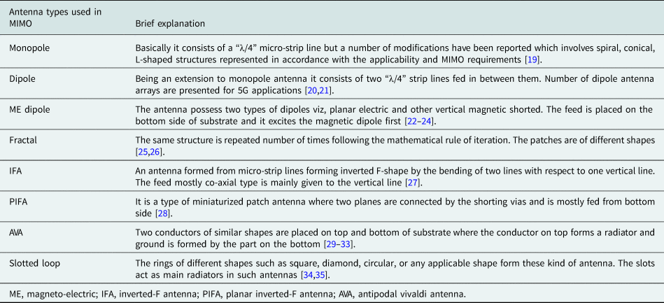
Table 4. Brief description of advantages and disadvantages of different types of antennas

The 5G antennas can also be classified in terms of the applied ports viz, antennas with single input and output ports and antennas with multiple input and output ports as shown in Fig. 6. The 5G antenna designs on the basis of number of I/O (input-output) ports are defined briefly as follows:

Fig. 6. Classification of 5G antennas based on I/O ports
SISO antennas
The type of antenna is quite simple in terms of design and implementation. It has been reported in literature that these antennas are implemented either with a single element or multiple elements employed for 5G mobile applications. Single input single output (SISO) antennas have an advantage of easy integration into the 5G mobile devices. For the frequencies above 6 GHz, the single antenna service quality gets degraded by the effect of propagation losses which the signals are prone to. So in order to overcome those losses multiple antenna system forms a better option [Reference Albreem, Juntti and Shahabuddin14]. The single antenna due to its larger size becomes incapable for mobile terminal devices. Single antenna provides high gain but at the cost of larger size [Reference Vannithamby and Talwar13].
Table 5 summarizes briefly the SISO multiple element mobile terminal antennas reported in the literature. It can be generalized from Table 5 that the technique of making slots etched from the ground planes acting as main radiating elements enhances broadband operation required for cellular communications. But some of the drawbacks of using these techniques include the introduced complexities in the design procedure in addition to the larger sizes of the antenna designs which add to the interference with all other circuit elements present on the mobile PCB devices.
Table 5. Table explaining the single input single output antennas applicable for communication devices

MIMO antennas
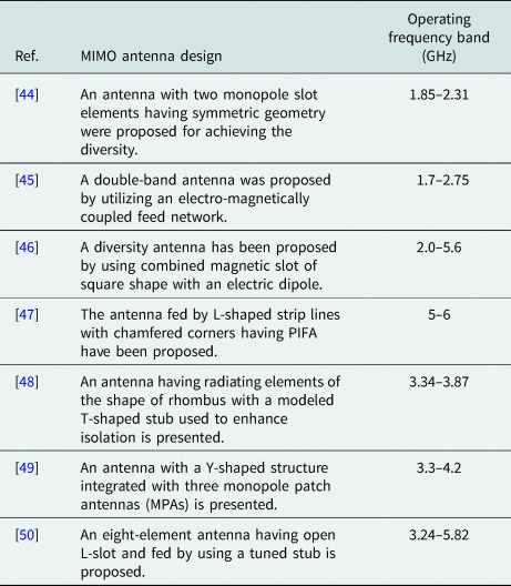
In mobile wireless communication systems, there are a number of unwanted factors that include maximum interference, more radiation losses, multi-path fading, etc. which go increasing as we approach toward the higher frequencies. To minimize all the related issues, MIMO antennas are proving a good option. In MIMO technology, the key challenges to be addressed include high efficiency for each element and low correlation between the elements [Reference Khan, Al-Hadi, Soh, Kamarudin, Ali and Owais7]. Table 6 shows the antenna features of the MIMO antennas structured for hand-held devices according to the literature. With very small space between the antenna elements, the mutual coupling between them is quite prominent. The coupling arises due to the presence of surface waves, free space radiations, and surface currents. In antenna arrays, coupling is mostly due to free space radiations and surface currents whereas for micro-strip antennas it is because of surface waves only. This has an adverse effect on the reflection coefficient of the MIMO antenna systems. MIMO system strengthens the range of transmission without any increase in the power of a signal. The application of MIMO in 5G reduces latency, increases efficiency and throughput with the enhanced channel capacity. Depending upon the frequency, MIMO antennas can be multi band as well as broad band including the MIMO antennas that posses a metal rim and those which do not have any metal rim [Reference Chen, Chen, Zhang and Zhao43].
Table 6. Table explaining the multiple input multiple output antennas applicable for 5G communication devices
Double and multi-element MIMO antennas without metal rim
The MIMO designs having two elements or multiple number of elements without metal rims around the mobile terminals are extensively present in the literature. The MIMOs consist of same structures of antenna elements with prominent separate feed for the individual elements. There is an important factor of attaining maximum isolation between the antenna elements for the whole MIMO designs to function efficiently. Dielectric resonator antenna (DRA) elements are used in MIMO designs as they provide high gain, comparable isolation as well as enhanced efficiency. In MIMO DRAs, the isolation can be increased by using shields such as meta-surfaces [Reference Dadgarpour, Zarghooni, Virdee, Denidni and Kishk51], feeding mechanism with hybrid techniques [Reference Yan and Bernhard52–Reference Abdalrazik, Abd El-Hameed and Abdel-Rahman54], FSS (frequency-selective surfaces), etc. These isolation techniques aim at changing the current densities among the elements of the MIMO antenna. The isolation among the DRA elements can also be increased by loading the metal strips over the resonator surfaces. It reduces the correlation between the adjacent elements by diverting the coupling field away from each other. In order to reduce mutual coupling between the antennas, neutralization lines and several other decoupling techniques are employed [Reference Foroozanfard, De Carvalho and Pedersen55–Reference Wang and Du59]. A neutralization line is embedded in between the elements of MIMO antenna in different ways applicable to enhance isolation [Reference Wang and Du60,Reference Guo, Cui, Li and Sun61]. Better isolation can also be achieved by using the antennas possessing self decoupled structures [Reference Ren, Zhao and Wu62]. Table 7 summarizes the comparison of MIMO antenna design without metal rim.
Table 7. Comparison parameters of the MIMO antennas without metal rim

Mobile terminal antennas with metal rim
In current world, there is an increase in the development of mobile smart-phones with metal rims that mostly employ MIMO antenna structures. They are becoming the key technologies that are mainly suited to 5G wireless applications. Such antennas with metal rims are offering high level robustness along with the attractive external appearance. A loop antenna having two parallel loops is loaded on the ground which is excited by coupled feed line of L-shape [Reference Zhang, Ban, Sim, Guo and Yu68]. An antenna with three patches having a small gap that connects it to the ground plane is presented in [Reference Lian, Ban, Yang, Zhang, Sim and Kang69,Reference Cai, Li, Zhang and Shen70] It is a MIMO metal rim antenna of compact size because of IF (inverted-F) design in addition to the stubs required for tuning. Table 8 summarizes the comparison parameters for metal rim MIMO antennas.
Table 8. Comparison parameters for MIMO antennas with metal rim

With the increasing demand for the higher data rates that too when there is a shortage of bandwidth in the available spectrum, the smart-phones employing efficient antennas are being widely required for 5G applications. In view of the 5G standardization, the design of mobile terminal antennas is very critical. In [Reference Lai and Wong75] an integrated antenna having substrate with ME dipole is presented for 4.98–6.04 GHz range. A printed broadband antenna for MIMO applications for 5G 3–9 GHz has been presented in [Reference ul Haq, Khan, Islam and Lee76]. A MIMO mobile terminal with four ports has been investigated for 5G in [Reference Abdullah, Ban, Kang, ford Sarkodie and Li77].
Analysis for performance enhancement in the antennas for 5G applications
In order to enhance the performance and meet the requirements for 5G technology, the parameters of MIMO antenna design that include efficiency, gain, bandwidth, reduction in mutual coupling, size miniaturization, etc. need to be optimized. In Table 9, we have summarized the standard techniques that enhance the performance of the antennas to a considerable extent.
Table 9. Techniques employed in MIMO antennas to enhance their performance

The techniques employed for enhancing the performance of antenna designs have some merits and demerits which can be quantified in terms of certain antenna parameters as shown in Table 10.
Table 10. Merits and de-merits of different techniques used for performance enhancement of MIMO design

The parametric metrics important for the better performance of the MIMO antenna designs include envelope correlation coefficient (ECC) and mean effective gain (MEG). The important linked metrics are evaluated by using ECC and MEG. For wireless mobile communications, ECC is treated as one of the most important parameters [Reference Sharawi89]. ECC can be defined as the amount of field correlated between the antenna elements in a MIMO design. In order to obtain high capacity and high diversity gain, ECC must be very low [Reference Sun and Wei90]. The acceptable amount of ECC is 0.5 however in case of 4G communication systems the revised value is 0.3 [Reference Lee, Kim, Ryu and Woo91,Reference Sharawi92]. ECC in case of multi-antenna system is evaluated either from S-parameters or radiation patterns in the far field. The S-parameters method is not efficient in most of the cases while as in the far-field pattern method those disadvantages can be overcome [Reference Sharawi, Hassan and Khan93]. The efficiency of the antenna elements is determined by the ratio of power radiated to the power transmitted into the free space. From the standard far-field radiation pattern method, the efficiency can be calculated as [Reference Pan, Papapolymerou, Tentzeris and Balanis94]:

where, E θ represents field pattern in the vertical direction. E ϕ represents field pattern in horizontal direction. Another important parameter to evaluate antenna efficiency is to quantify the amount of energy collected by the antenna from its surroundings [Reference Pan, Papapolymerou, Tentzeris and Balanis94]. The far-field radiation pattern method used to calculate the efficiency in terms of mean effective gain can be written as η = 2(MEG). The performance enhancement parameters of a MIMO design are specifically shown in Fig. 7
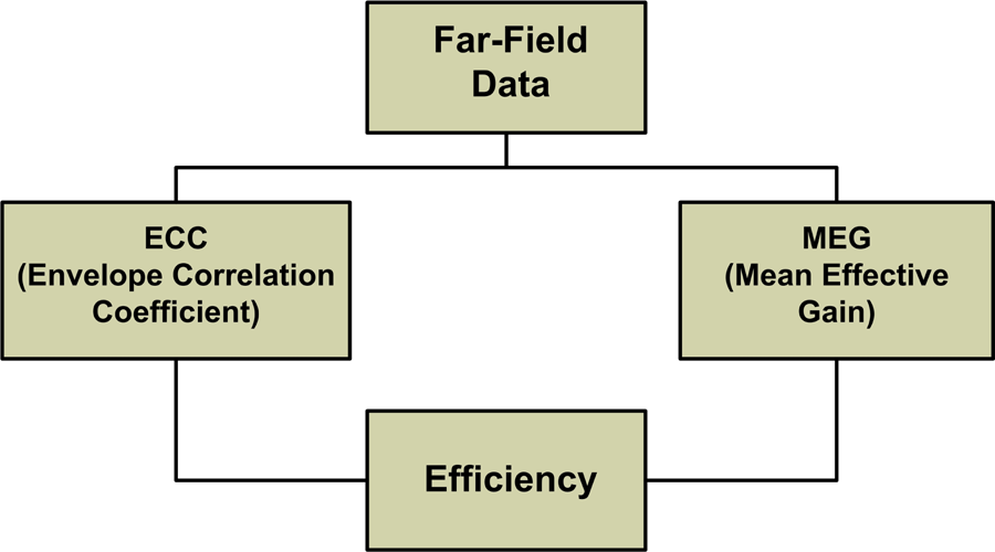
Fig. 7. Performance enhancement parameters for MIMO design.
Mutual coupling in MIMO antennas
In terms of energy, coupling may be defined as energy absorbed by a non-radiating antenna which is in the vicinity to a radiating antenna. It is observed to change the reflection coefficient, radiation patterns as well as input impedance of the antenna elements in an array. In [Reference Savy and Lesturgie95], the empirical model of coupling was presented as:


where, C mn → mutual coupling, d mn → distance between m thandn th antenna elements, α → coupling level control factor, N → number of elements in the array. Practically, mutual coupling depends on the configuration of the elements of antenna array as well as on the excitations of the rest of the elements. The S-parameter factor (dB valued) between the m thandn th elements represented by 20log10(|S nm|) is used to quantify the coupling factor. [Reference Allen and Diamond96] explains the mutual coupling effects in transmitting mode and receiving modes.
Transmitting mode effect
In case of multi-antenna system, multiple ports may possess phase excitations of random order during the transmission mode. It has a prominent impact on impedance matching as well as mutual coupling of the elements of the antenna system. total active reflection coefficient (TARC) may be defined as the square root of total power generated subtracted from the total power generated by all phase excitations divided by total power generated [Reference Manteghi and Rahmat-Samii97]. TARC is the parameter required to measure reflection coefficient of a MIMO antenna array having different phase excitations at the multiple element ports. Under the multiple phase excitations at different ports, TARC takes the account of impedance matching, mutual coupling, and radiation efficiency. TARC is worse because of high mutual coupling.
Receiving mode effect
When the antenna element is in the receiving phase, the antenna performance can be investigated by exciting one element while terminating the other element by the load of 50Ω. The mutual coupling between the antenna elements in a multi-antenna system has a prominent effect on the antenna parameters which mainly include ergodic channel capacity [Reference Chen and Kiang98], diversity gain [Reference Plicanic, Lau, Derneryd and Ying99], throughput [Reference Fan, Kyösti, Ji, Hentilä, Chen and Pedersen100], reflection coefficient and radiation parameters, and error rates [Reference Lu, Hui, Bialkowski, Lui and Shuley101]. Figures 8(a) and (b) depict the mechanisms of mutual coupling in transmitting mode and receiving mode. As an example if we take two elements in antenna array such as “p” and “q” and assuming an attached source to “q”, the energy generated by source 1 is radiated into space 2 toward the p th element. A part of this received energy by p th element is re-scattered to the space 4 and rest is traveled toward 5. A small part of this energy 4 is being picked up by the q th element. This process of mutual interaction is indefinitely continued which explains the mutual coupling mechanism in the transmitting mode. While as in the receiving mode, if we assume wave 1 impinging on to this array it is seen to induce some current first in the element “p”. A fraction of this goes to receiver 2 and rest will be scattered into space 3 of which a part might be directed toward 4 where it is added to plane wave 5. The antenna performance can be investigated by exiting one element by another one that is ended on a 50Ω load [Reference Chen, Zhang and Li102].

Fig. 8. Mutual coupling mechanism in (a) transmitting mode and (b) receiving mode.
Methods to reduce mutual coupling in MIMO antennas
A number of techniques reported in literature are being used to count for maximum isolation among the antenna elements in a MIMO system. One of the simple methods to achieve the greater isolation is to increase the distance between the antenna elements; due to minimum space inside the mobile device, the method is not much feasible. Another method is to employ the polarization diversity but this too has an adverse effect on the gain parameter of the antenna and on the evaluation of spatial multiplexing in case of MIMO devices. The techniques employed to reduce the mutual coupling or to enhance the isolation between antenna elements largely depend on the antenna structure. The techniques used must not largely effect the other parameters to a greater extent. The techniques used for decoupling that are present in the literature include the use of neutralization lines between the antenna elements placed in accordance of producing the better results [Reference Ban, Chen, Chen, Kang and Li103], ground strips and stubs of different shapes based on mode of antenna operation [Reference Ishteyaq, Masoodi and Muzaffar104], slots in the ground and the defected ground structures, parasitic elements capable of changing surface current paths for improving isolation [Reference Li, Zhai, Ma, Liang, Yu and Liu105]. In addition to these, the use of de-coupling networks [Reference Pan and Cui106], meta-material structures, meta-surfaces [Reference Dadgarpour, Zarghooni, Virdee, Denidni and Kishk51] aid in the improvement of isolation in MIMO antennas.
Neutralization lines (NL) introduce opposite phase having same amplitude, which cancels out the coupling between the elements. The NL when connected between the planes enhance size miniaturization as well as bandwidth [Reference Nadeem and Choi107]. In [Reference Jiang, Liu, Cui and Hu108], the ground slots are connected by the NL where the transmitted conductive current on the line is neutralized by the current induced resulting in the reduced coupling between antenna elements. A neutralization line consisting of two strips and a disc has been used to create different number of current paths for decoupling as presented in [Reference Zhang and Pedersen109]. The lines of different lengths create paths to cancel out the coupling field and enhance isolation. The ground strips have also been employed for increasing the isolation between the dipole antenna elements for 5G applications in. A Quasi yagi MIMO antenna having two elements has been proposed in [Reference Ishteyaq, Masoodi and Muzaffar104] where a ground stub has been placed in between the elements in order to reduce the mutual coupling in the MIMO design. The MIMO antenna design and the resulting parameters are shown in Fig. 9. Electromagnetic band gap structures act as a transmission medium for the electromagnetic fields that enhance the efficiency and reduce the mutual coupling among antenna elements. In [Reference Yang, Xiao and Ye110], the mushroom-shaped integrated EBG structures have been proposed among the antenna elements for reducing the mutual coupling. The decoupling networks transform the admittance to an imaginary value and acts as a resonator for decoupling between multiple elements. A parasitic element having H-shape have been incorporated for reducing the mutual coupling in [Reference Mak, Rowell and Murch111]. In [Reference Zhao and Wu112], the four-element antenna array has been loaded with the reactive parasitic structures for enhancing isolation. A DRA with dual-polarization with wide band operation and enhanced isolation has been presented in [Reference Kowalewski, Eisenbeis, Jauch, Mayer, Krestchmann and Zwick113]. The modifications in the ground plane suffice to provide the characteristics same as that of band stop filter. In this technique, mostly a slot is made in between the MIMO elements on the ground plane. The slot restrains the fields to couple between antenna elements thus reducing coupling [Reference Ouyang, Yang and Wang114]. Meta-materials of different structural shapes and meta-surfaces are able to reduce the mutual coupling to a large extent in the MIMO antennas [Reference Dixit and Kumar32]. Split ring resonator structures also form an effective means for reducing the mutual coupling between the antenna elements. The different techniques used for reduction of mutual coupling between the antenna elements is shown in Fig. 10. Table 11 briefly summarizes the merits and de-merits of the different isolation enhancement/decoupling techniques.

Fig. 9. Two-element quasi-Yagi MIMO antenna design. (a) Antenna schematic, (b) S 11dB, (c) mutual coupling [Reference Ishteyaq, Masoodi and Muzaffar104].

Fig. 10. Techniques for reduction of mutual coupling.
Table 11. Merits and de-merits of isolation enhancement techniques in MIMO antennas

Isolation enhancement in massive MIMO
Massive MIMO is an extended version of MIMO technology with more than hundred antennas forming an array with directivity to be considered an extra dimension for freedom. The technology is mainly employed at the base stations focusing to form an essential means for 5G wireless mobile communication systems. In this part, a brief review about the basic decoupling techniques for enhancement of isolation between the antennas in the massive MIMOs at the base stations has been summarized. In massive MIMO antennas, the coupling must be <−30 dB in accordance to the industry thumb rules. In [Reference Gao, Ma, Wang, Zhang and Parini123], a high gain stacked patch antenna having dual polarization with very low coupling between the antenna ports is presented. The massive MIMO structure is composed of 144 total ports having patches pointing in different orientations. The isolation can be enhanced by using array antenna decoupling surfaces [Reference Wu, Wei, Mei and Zhang124], thin planar meta-material-based lens [Reference Jiang, Chen, Zhang, Hong and Xuan125] and so on in case of massive MIMO antenna designs.
SAR in reference to the safety of users
To meet the requirements for the deployment of 5G wireless bands, the antenna designers have capitalized for the antenna array systems. The sub-6 GHz frequency band is becoming the band of interest for 5G communication in most of the countries worldwide [Reference Qi, Yang, Liu, Fan, Orlandi, Kong, Yu and Yang126]. The MIMO antenna performance has a prominent influence by the housing effects inside the mobile terminal and also in the vicinity of the users hands [Reference Li, Sim, Luo and Yang127,Reference Di Paola, Syrytsin, Zhang and Pedersen128]. The antenna designers need to take into account the influence of human biological tissues on the antenna performance and vice-versa. Its not feasible to decrease the transmitting power levels and sensitivity toward the receiving levels. The coupling of EM fields between the antenna and the human needs to be reduced considerably for the safe user handling of the device [129]. The EMW radiations pose hazardous effects on the human health wherein the energy being absorbed by the body gets changed into heat causing the rise of temperature and thermal effects on it [Reference Nazeri, Abdolali and Mehdi130]. An important parameter that evaluates this energy absorption is determined by the SAR. [Reference Isa, Al-Hadi, Azemi, Ezanuddin, Lago and Jamlos131] presents four-band antenna array that has been loaded on different positions on the mobile PCB and it has been studied that SAR values need to be very low mainly at a distance where the antenna is faraway from human head. An antenna with the rectangular radiating slot and T-slot for dual band operation has been analyzed for SAR effects in [Reference Ishteyaq, Shah Masoodi and Muzaffar132]. It has been proposed in the literature that for users’ safety the SAR value must be <2 W/kg for the mobile terminal antennas in order to prevent them from the harmful exposure to EM waves. The work in Fig. 11 shows the MIMO antenna design having closed loop parasitic elements as decoupling networks. The resulting parameters and the schematic of the design are shown in the respective figure. The parasitic elements have reduced the coupling to <−20 dB and also the SAR result is acceptable, i.e. < 2 which is considered to be very safe for the user applications.

Fig. 11. Six-element MIMO antenna. (a) Antenna schematic, (b) S 11dB, (c) mutual coupling, (d) SAR [Reference Ishteyaq, Masoodi and Muzaffar133].
Challenges in the design of MIMO for 5G applications
In order to enable essential trends, few remarkable challenges in antenna design are needed to overcome. The section summarizes some major challenges that are required to be addressed.
(1) 5G is intended to hold up a wide range of user cases that include massive IOT, critical control mission, and enhanced mobile broadband. To ensure the availability of the spectrum, 5G should be able to work on diversified bands and spectrums including shared band, licensed bands, unlicensed bands, and lower sub-6 GHz to millimeter-wave bands. An important challenge for 5G antenna designs is the delivery of most capable interface to support the requirements of spectrum and user cases.
(2) One more challenge for the 5G antenna design is to allow the continuous technological evolution in addition to compatibility in forward direction. The major components to be analyzed for wireless applications can be shown as:
(a) The flexibility in the spectrum is needed for supporting the devices operating on different spectral bands.
(b) In order to support the large range of expected end points, scalable air interface is needed.
(c) For technological evolutions and supporting future requirements, air interface having forward compatibility is essential.
(3) There is an inevitable demand for massive connectivity for wireless systems with the development of IOT devices in the coming time. This ever-increasing demand for more connectivity of machine to machine devices is mainly specified by high reliability, less complexity of transmission, extremely low power consumption, low latency, etc. These challenges need to be addressed and it is expected that 5G networks designed need to be more network centric, less scalable, and mostly targeted for human-based applications.
Since the mm-waves have promised the high speed point-point communications, there is a problem of blocking these signals by atmospheric oxygen and rain which makes it specific to short-range communication. One of the methods to harness this spectrum is beam-forming wherein a beam is directly targeted on a device. For this, the antennas at base-stations or in the devices need to be designed in such a way to handle this complexity for directing a beam to the target in cellular overcrowded environment with a number of obstructions. These 5G systems require such antennas with high gain mainly to overcome the atmospheric losses. To design high gain antennas at the limited available energy has been a challenge ever since for the designers.
Critical review on 5G design aspects and summary
The 3GPP (third generation partnership project) has released the upgradation of the 5G network standards from time to time which has enabled the research community to clarify their objectives mainly to commit toward the development. It is not only smart-phones that will support the 5G technology; rather the IOT devices will be in need of the supportive antennas with stable patterns, low path losses, low latency for providing wide range of services such as smart city, etc. The 5G technology is going to unleash more opportunities to break the traditional boundaries toward the development. Since the technology is supporting IOT, there will be a transformation in major fields including healthcare, education, and many more social sectors. To suffice the needs for better communication, 5G technology will decipher pervasive IOT system where numbers of devices are to be connected while maintaining network speed, cost, latency trade-offs. The 3GPP standards are continuously undergoing some changes. For 5G wireless networks, the 3GPP has defined three usage schemes stated as follows: [Reference Union134]
(1) MTC (massive machine type communications): The scheme supports the IOT in order to connect more number of devices, as thousands of devices can be supported by a single base-station for smart-grid, smart-city applications.
(2) eMBB (enhanced mobile broadband):It supports the extremely high speeds for both indoor as well as outdoor connectivity providing around 20Gbps data-rates for indoor and 2Gbps for outdoor areas.
(3) uRLLC (ultra-reliable and low latency communications): It possesses an inflexible requirement of low latency <1ms and a packet loss of 1 in 1000 packets. Some of the occurrences include the safety in the transportation, manufacturing process control, and medical surgery.
The problems of multipath fading interference and radiation losses are prominent in wireless communications which become quite severe at the high frequencies. In order to overcome these problems, the application of MIMO technology has become quite important because it enhances the range of transmission without much increase in the power of a signal. In 5G, the MIMO antenna technology is used to accomplish the good efficiency, lower latency, and maximum throughput. The MIMO technology can be efficiently utilized to launch more signals while using multiple number of antennas thereby improving the channel capacity. Based on the operating frequency bands, the MIMO antennas have been classified as multi-band and wideband, which are further classified as multi-element antennas without rim and multi-element antennas with rim.
Antennas with metal rim provide the mechanical strength to smart-phone devices in addition to their aesthetic look. When the number of radiating elements in the transmitter or receiver side is very large, the MIMO is referred to as massive MIMO system [Reference Kumar, Dixit, Malekar, Raut and Shevada135]. In massive MIMO technology, because of large number of antenna elements, there is an enormous increase of SE. One of the important methods for improving the throughput of the MIMO antennas is beam-forming by the antenna array. Beam-forming refers to the regulation of the phase of the transmitting signal to get a major beam in one particular desired direction. The beam-forming can be performed both in analog as well as digital domain. The analog domain beam-forming is applied for single-user systems while as remaining two are used for multi-user systems [Reference Kutty and Sen136].
A brief review for the MIMO antenna technology toward the application for future 5G wireless communication networks has been summarized in the given section. The paper is supposed to provide an easy path for the new researchers to design the antennas taking into account all the parameters responsible for enhancing the performance of MIMO antennas for 5G applications. The paper gives an insight to the different types of antennas that mainly include SISO antennas which are mostly employed in the devices where compactness in the physical size of antenna is critical. The MIMO antennas form an important part for smart-phones in reference to their support for beam-forming, etc. An important advancement to MIMO is massive MIMO technology ensuring better spectrum efficiency as well as throughput mainly for the base station application. One of the most crucial factors for MIMO applications is the effect of mutual coupling on the antenna performance. A number of techniques are being used for reducing the coupling effect between the multiple elements in a MIMO design. It is desirable that there must be low correlation of field power among the elements. Table 12 summarizes briefly almost all the crucial parameters for the MIMO antenna designs that are present in the literature.
Table 12. Summary of the MIMO antenna parameters for 5G wireless applications

Conclusion
In the paper, a thorough review of SISO antennas, single-user MIMO, multi-user MIMO, and massive MIMO technologies is presented for 5G wireless systems. The antennas have been reviewed by analyzing some important parameters that mainly include the effects of mutual coupling on the antenna performance in addition to the safe user handling of the mobile device. The review paper has been devised with the aim to provide a summary of MIMO antenna design for 5G applications implemented for smart-phones as well as for base stations. The main focus is to review the spectrum evolution toward 5G that includes both mm-wave and sub-6 GHz bands in addition to their pros and cons. Based on the properties and availability of the spectrum, the design of the antennas has been focused on. The MIMO antennas for mobile terminals are mostly designed with metal-rimmed edges or without metal rims. The effects of mutual coupling due to close spacing of MIMO antenna elements and its impact on the correlation are determined by ECC. The main takeaways of this review are categorized as:
Evolution of spectrum toward 5G
The main focus of the future researchers is to use the 5G spectrum bands in parallel to all other existing cellular frequency bands. Most of the countries worldwide have intensified their research for 5G applications. 5G spectrum allocation of bands include sub-6 GHz range and mm-wave range. The sub-6 GHz bands include mainly n77 (3.3–4.2) GHz, n78 (3.3–3.8) GHz, n79 (4.4–5) GHz, LTE-U (5.15–5.925) GHz; however, majority of the work is focused on (3.4–3.6) GHz and (5.15–5.925) GHz bands. The millimeter-wave bands include (24.25–39.5) GHz, (37–43.5) GHz, (45.5–47) GHz, (47.2–48.2) GHz, (66–71) GHz. The technology operating in both high- and low-frequency bands offer quite higher data rates of around 20 Gbps and more than 100 Mbps on an average. 5G specifies low latency, high mobility, supports more number of users at a time with enhanced antenna gains, broader bandwidths, and minimum radiation losses.
Mutual coupling and antenna performance
The MIMO antenna designs for mobile and base station applications and the decoupling techniques are being presented. The isolation improvement techniques include the use of neutralization line, slotted and defected ground structures, parasitic elements, ground strips, meta-materials, etc. The techniques applied depend on the design of MIMO antenna elements in addition to their frequency of operation. The correlation between the antenna elements is also explained along with their effect on the antenna performance. The paper also presents the promising coupling reduction techniques for base station antennas in addition to mobile terminal antennas.
SAR in terms for safe user handling
The antennas for mobile terminals should also take into account the effects of proximity of the user during the working of device. Due to the properties of biological tissues related to absorption of electromagnetic waves, SAR becomes an important parameter. The paper has discussed a number of antennas in the literature, analyzed for the SAR values. For the safe application of the mobile devices, work is being done to make the SAR values <2. The 2 W/kg has been set as the safety limit by the IEEE. The review sets a better understanding of all the aspects for the design of MIMO mobile antennas for 5G applications.
Future applications
The increasing demand for faster, smarter, and completely secure networks has increased rapidly the requirement for high data rates. The 5G is proving to be efficient in terms of energy and offering low latency, more scalability, high throughput, and more reliability. The main requirements for 5G networks are fulfilled by some notably important technologies that mainly include massive MIMO, densification of networks, radio access networks, device to device communication, and resource virtualization. The future applications for 5G can be briefly summarized as:
(1) Cloud computing/IOT fog for 5G The 5G-IOT is becoming an emerging field keeping in consideration with the need for higher data rates and faster communication networks. With 4G technology, only up to 2000 devices could be connected; however, 5G supports high connection density of around 1 million devices over 0.38 sq. miles [Reference Shafique, Khawaja, Sabir, Qazi and Mustaqim150]. The most suitable antennas for 5G IOT are multiple-element phased antennas having beam-forming networks, ultra-wide band monopole antennas, and massive MIMO [Reference Bhattacharjee, Saha, Santra, Banerjee and Ghatak151,Reference Alagarsamy and Shanthini152]. In the near future, the combination of AI(artificial intelligence) and 5G-IOT is going to play an effective role in the development of smart systems.
(2) Smart-phone application For smart-phone applications, multi-band MIMO antennas are generally suitable; however, it also becomes a challenge to put these multiple elements in the limited space. Thus, the antennas that include monopole antennas, multi-mode loop, IFA are appropriate for smart-phone applications because of easy integration and compactness [Reference Ullah, Ullah, Kamal and Ullah153,Reference Chen and Chu154].
(3) Mobile platforms and base-stations In addition to high data rates, there is an increase in demand of more channel capacity for mobile platforms and 5G base-stations. The requirement can be full-filled by employing massive MIMO technology. Due to more number of base station antennas, it is possible to achieve high channel capacity in mMIMO. Besides capacity increase, mMIMO reduce energy consumption as well as latency, thus increasing EE [Reference Al-Tarifi18]. Multi-antenna systems are going to provide a gateway for 5G network because of spatial multiplexing and high beamforming that is going to improve capacity, increase coverage, and QoS (quality of service).
 Insha Ishteyaq received her bachelors in Electronics and Communication Engineering in 2013 from the University of Kashmir and her Masters in 2017. She is currently working toward her Ph.D. degree from Islamic University of Science and Technology with research interests in antenna design for 5G standards. She has published few papers in international journals and conferences. Her research interests include modern day antenna design, millimeter-wave antennas, microelectronics, and related applications.
 Khalid Muzaffar received his B.Tech in Electronics and Communication and M.Tech. in Communication and IT from NIT Srinagar, India in 2004 and 2006, respectively. He worked in Ericson India pvt ltd. From July 2006 to July 2007 as a field and maintenance engineer. He joined IUST Awantipora as an assistant professor in August 2007. He received Ph.D. from CARE, IIT Delhi, India in June 2017. His research interests are microwave antenna design, applications of thermal imaging for microwave field imaging.


