


Introduction
Traditional wireless communication systems are often designed for a single predefined goal. These antennas possess some fixed parameters such as polarization, radiation pattern, and frequency band. Frequency reconfigurable antennas have gained tremendous research interest in modern applications, such as radio frequency (RF) systems for satellite and wireless communications, imaging, sensing, and satellite communications. Several frequency bands are used by different wireless communication systems [Reference Kunwar and Gautam1, Reference Kunwar2] such as Bluetooth (2400 MHz), Wireless Fidelity (Wi-Fi at 2.45 GHz), WiMAX (3.3, 3.5, 3.7, 5.5, 5.8 GHz) and (WLAN at 5.4 GHz), Universal Mobile Telecommunications System (UMTS at 1900–2200 MHz), GSM (890–960 MHz), PCS (1.880–1.990 GHz), DCS (1.710–1.880 GHz), Global Positioning System (GPS at 1575 MHz), and Long Term Evolution (LTE at 2300–2400 MHz). Modern communication devices (such as laptop, tablets, Smartphones, etc.) require antennas that are capable of transmitting and receiving at multiple bands. This can be accomplished by using multi-band or frequency reconfigurable antennas. In the state-of-the-art literature, many designs have been proposed for realizing multi-band functionalities in a single antenna, by using cheaper and affordable substrate materials (i.e. FR-4, having relative permittivity and loss tangent of 4.3 and 0.002, respectively) [Reference Cao3–Reference Ali8]. In [Reference Cao3], a 44 mm × 54 mm antenna has been designed using a combination of a T-shaped patch, rectangular slot, T- and E-shaped stubs to cover the spectrum allocated for GPS (1575–1665 GHz) WLAN-802.11b&g (2400–2545 MHz), WiMAX (3270–3970 MHz), and WLAN-IEEE 802.11a (5170–5930 MHz) systems. The antenna gives sufficient gain (1.52–3 dB) and bandwidth (300–700 MHz). In [Reference Abed and Singh4], a 50 mm × 70 mm quad-band antenna has been proposed for 3G (2.1 GHz), WiMAX (3.43–3.78 GHz), Wi-Fi (2.4–2.56 GHz), and WLAN (5.8 GHz) communication networks. The aforementioned frequency bands have been achieved by using a defected circular patch as a feed strip and a Q-shape slot in the bottom ground plane. A metamaterial-inspired approach has been used in [Reference Hasan5] to design a compact antenna (42 mm × 32 mm) for LTE and WiMAX applications. The antenna gives good gain (3–3.7 dB) but relatively narrow bandwidth (60–730 MHz). In [Reference Thavakumar and Susila6], a multi-resonant FIFA with a relatively bulky size of 100 mm × 35 mm has been designed, which covers the GSM/IRNSS (Indian Regional Navigational Satellite System)/UMTS-DCS/PCS/LTE2300 and ISM frequency bands at 900 MHz/1.176 GHz/1710–1880 MHz/1850–1990 MHz/2305–2400 MHz and 2.4 GHz, respectively. The gain and bandwidth of this antenna vary from 1.14 to 2.23 dB and 80 to 500 MHz, respectively. The aforementioned antennas give multi-band performance, however they do not have the ability of reconfiguration to select one or more of its resonant bands. In [Reference Mansoul and Seddiki7], a triple-band frequency reconfigurable antenna with an overall size of 80 mm × 30 mm has been presented, which covers the 2.45 GHz band (Wi-Fi), 3.5 GHz band (WiMAX), and 5.8 GHz band (WLAN). A quad-band reconfigurable antenna diverse wireless applications, such as 1.6 GHz, Global Navigation Satellite System (GNSS); 2.5 GHz, lower WiMAX; 5.8 GHz, WLAN; and 9.8 GHz, X-band, have been reported in [Reference Ali8]. Recently Shah et al. [Reference Shah9] have proposed a 40 mm × 35 mm, Tri band seven-shaped monopole antenna, using a truncated ground plane with efficiencies of 76.55, 77.30, and 70.4%, obtained at 2.450, 3.50, and 5.44 GHz, respectively. The antenna presents fair gain (2–3 dB) and bandwidth (500–1250 MHz) in its three resonant bands.
In the emerging telecommunication world, reconfigurable patch antennas [Reference Petosa10, Reference Majid11] have become important and desired component for many modern communication systems. Due to these eye-catching features (size, low profile, light weight, easy to fabricate, cost, and multiple bands of frequency), researchers introduced efficient frequency reconfigurable planar antennas with various design approaches of radiating elements [Reference Jing12, Reference Iddi13]. Unique switching approaches were carried out in the past to design reconfigurable antennas. The basic switching techniques [Reference Haupt and Lanagan14] used for achieving reconfigurable features include optical, RF, Varactor, and PIN diode switches.
Comparison with published literature
Table 1 gives a comparative summary of the proposed antenna to the recently designed state-of-the-art antennas available in the literature. It is evident from this comparison that the proposed antenna gives fair bandwidth and gain in its six reconfigurable frequency bands, and is relatively compact in size than the antennas presented in [Reference Abed and Singh4, Reference Thavakumar and Susila6, Reference Mansoul and Seddiki7]. The antenna presented in [Reference Thavakumar and Susila6] gives hexa-band frequency response; however, it is relatively narrowband and is not reconfigurable. The proposed F-shape antenna has comparable dimensions relative to [Reference Cao3, Reference Hasan5, Reference Shah9]; however, [Reference Shah9] is triple-band and the antennas in [Reference Cao3, Reference Hasan5] are non-reconfigurable with only triple- and dual-band frequency response.
Table 1. Comparison with existing multi-band/reconfigurable antennas available in the state-of-the-art literature

This paper presents a compact frequency reconfigurable capital English alphabet (F)-shaped monopole planar antenna designed on a 1.6 mm thicker FR-4 substrate. The antenna is capable of functioning in multi-standard applications, including 3G Advanced, WiMAX, Wi-Fi, WLAN, and satellite communication. The resonant bands for the aforementioned applications are achieved by using lumped element (or RLC) switches. The lumped element switches are preferred as they are easily modeled and are conveniently integrated into the structure [Reference Yadav15]. The value of the resistance configure the state of the switch, i.e. R = 1 Ω (switch ON) and R = 1 kΩ (switch OFF).
The paper is structured in the following sections: design theory and structural details are outlined in “Antenna design and layout” section. “Experimental and simulated results” section elaborates and compares simulations and measurements. “SAR analysis” section sheds light on specific absorption rate (SAR) analysis of the antenna on a flat section of human body. Finally, the conclusions and future directions are outlined in “Conclusion” section.
Antenna design and layout
The dimensions and geometry of the proposed switchable planar antenna is portrayed in Fig. 1. The radiating F-shape element is backed by an FR-4 substrate (having thickness of 1. 6 mm, loss tangent of 0.019, and relative permittivity of 4.5). Truncated ground plane is used to obtain the desired bandwidth and radiation response. A 50 Ω microstrip feed line of width w = 3 mm is designed using the standard transmission line theory [Reference Balanis16]. The proposed antenna is excited by assigning an SMA port to the feed line.

Fig. 1. Various geometrical views of the proposed F-shape antenna: (a) front, (b) side, (c) rear.
For installation of the switches within the antenna structure, two slots of 1 mm are restrained as depicted in Fig. 1. The transmission line model theory [Reference Balanis16] is used to calculate the effective length of the planar monopole antenna i.e.:
T 2.1 GHz = 49.58 mm (3/4Tf + T1 + T2 + T3 + T4 + T5 + T6 + 3/4T7 + 2W),
T 2.4 GHz = 38.31 mm (Tf + T1 + T2 + T3 + T4 + T5 + 2W),
T 3.35 GHz = 32.73 mm (3/4Tf + T1 + T2 + T3 + T4 + 1/4T5 + W),
T 3.5 GHz = 30.81 mm (3/4Tf + T3 + T1 + T2 + T4 + W),
T 5.28 GHz = 26.51 mm (W + T7 + T6 + T5 + T1 + T2 + T4),
T 5.97 GHz = 27. 31 mm (W + T6 + T5 + T3 + T2 + T1).
These effective resonant lengths (T values) are calculated from the surface current distributions for the given frequency modes. These lengths are approximately equal to one-quarter of the guided wavelength, i.e.
 $$T_{\,f_r} = \displaystyle{c \over {4f_r\sqrt {\varepsilon _e}}}, $$
where, c = 3 × 10⁸ ms−1 is the velocity of light in vacuum, f r is the resonance frequency, and ε e is the effective permittivity of the substrate, given by:
 $$\varepsilon _e = \displaystyle{{\varepsilon _r + 1} \over 2} + \displaystyle{{\varepsilon _r - 1} \over 2}\left( {1\; + \; 12\displaystyle{h \over w}} \right)^{ - 0.5}.$$
In (2), ε r is the relative permittivity, W is the width of radiating material, and h is the height of the substrate. The dimensions of the proposed antenna are listed in Table 2.
Table 2. Summary of dimensions of proposed antenna

Experimental and simulated results
The antenna is fabricated (Fig. 2) on a relatively cheaper and affordable substrate material (FR-4) with dielectric constant of ε r = 4.5. The antenna is tested through an Agilent Vector Network Analyzer (VNA) by measuring its parameters, such as return loss, antenna gain, directivity, VSWR, and radiation pattern to validate the simulation results. For excitation of the antenna, a waveguide port is assigned through feed line. Two lumped element switches (SW1, SW2) are used for possible four modes of operation (Table 3). Lumped element switch is preferred as it is easily modeled in CST MWS as a resistor (or wire) of 1 Ω and 1 kΩ, to keep the switch in ON and OFF state, respectively. For the proof of concept, a piece of copper wire is soldered across the gap (reserved for the installation of the switches) as shown in Fig. 2. This wire acts as a short circuit (switch = ON). To turn OFF the switch, the wire is de-soldered or open circuited.

Fig. 2. Fabricated F-shape monopole antenna: (a) top view, (b) rear view.
Table 3. Frequency modes of the proposed antenna

The scattering parameters of the antenna are measured using a VNA (Agilent N5242A PNA-X series). The radiation pattern of the antenna in the E-plane (YZ, ϕ = 90°) and H-plane (XZ, ϕ = 0°) is recorded in open air, using the measurement setup shown in Fig. 3. The antenna is fixed on the turn table (or positioner), and the polar pattern is recorded by using 3° angular steps between neighboring samples. That is, the turn table rotates the proposed antenna in 120 equal-angle steps (3° apart from each other), in order to capture a complete E or H-plane polar pattern. A high gain log-periodic antenna is used as probe antenna.

Fig. 3. Setup for measurement.
Reflection coefficient
The antenna operates in mode 1, when the two switches are set in the OFF-state. In this mode, it acts as a single-band antenna with a simulated and measured reflection coefficient of −25.4 and −44.5 dB, at 3.5 GHz, respectively (Fig. 4(a)). It operates in mode 2, when SW1 and SW2 are turned ON. In this mode, the antenna gives simulated and measured reflection coefficient of {−15.67 and −20.9 dB} and {−15.6 and −34.5 dB} at 2.1 and 5.28 GHz, respectively (Fig. 4(b)). When SW1→OFF and SW2→ON, the presented monopole antenna operates in single-band mode 3 (3.35 GHz), resulting in a simulated and measured reflection coefficient of −23.09 and −34.8 dB at 3.35 GHz, respectively (Fig. 4(c)). When SW1→ON and SW2→OFF, the antenna operates in a different dual-band mode 4 (2.40 and 5.97 GHz). In this mode, the simulated reflection coefficient of −20.0 and −17.1 dB and measured reflection coefficient of −21.6 and −45.0 dB are obtained at 2.4 and 5.97 GHz, respectively (Fig. 4(d)). The proposed F-shape antenna has a maximum −10 dB bandwidth of 1220 and 1020 MHz at 3.5 and 3.35 GHz, respectively.

Fig. 4. Compassion of simulated and measured reflection coefficient. (a) Mode 1 (3.5 GHz), (b) mode 2 (2.1 and 5.28 GHz), (c) mode 3 (3.35 GHz), (d) mode 4 (2.40 and 5.97 GHz).
From the results, it is evident that the antenna operates at six frequency bands 2.1, 2.4, 3.35, 3.5, 5.28, and 5.97 GHz, which cover the required 3G Advanced, Wi-Fi, WLAN, WiMAX, and satellite bands, respectively. In all the four modes of operation, the measured and simulated results are in good agreement in the lower frequency bands. There are slight shifts or variations in the simulated and measured reflection coefficients at the higher frequency ends (5.28 and 5.97 GHz), due to the differences in the level of accuracy set in the CST MWS during simulation and that maintained in the laboratory during measurements. Another reason for this difference is that the SMA port is properly balanced at the lower frequency bands (2.4 and 3.5 GHz), but slightly imbalanced at the higher frequency bands. It is worth mentioning that the antenna is never detuned from its standard frequency band, irrespective of the slight difference between the measured and simulated resonant frequency.
Surface current plots
The surface current radiated by the presented monopole antenna at 2.11, 2.40, 3.35, 3.50, 5.28, and 5.97 GHz are depicted in the two-dimensional surface plots of Fig. 5, which clearly highlights and encircles the effective resonant length corresponding to each frequency band. It is evident from the plots that resonant length is inversely proportional to the frequency, i.e. the overall F-structure radiates at the lowest frequency band of 2.1 GHz (Fig. 5(a)), whereas a small segment of the radiating patch (within the vicinity of the SW1) radiates predominantly at the highest frequency band of 5.97 GHz (Fig. 5(f)).
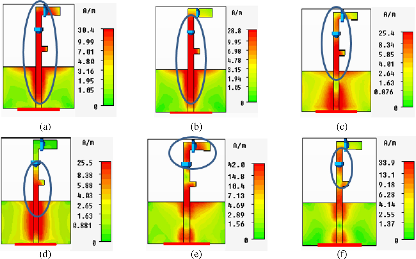
Fig. 5. Surface current plots: (a) 2.10 GHz, (b) 2.40 GHz, (c) 3.35 GHz, (d) 3.5 GHz, (e) 5.28 GHz, (f) 5.97 GHz.
Radiation pattern
The radiation pattern of the antenna is measured in open air using the setup of Fig. 3. The antenna is linearly polarized; therefore, its E- and H-plane patterns are studied for getting an insight about its radiation characteristics in the two orthogonal planes. The simulated and measured H- and E-plane gain patterns of the proposed antenna at 2.1, 2.40, 3.35, 3.5, 5.28, and 5.97 GHz are portrayed in Fig. 6. In mode 1, the peak gain of the proposed planar antenna is 2.81 dB at 3.5 GHz. When switched to mode 2, a peak gain of 1.96 and 2.67 dB is attained at 2.1 and 5.28 GHz correspondingly. In mode 3, the peak gain of the introduced monopole antenna is 2.67 dB at 3.35 GHz. Finally, in mode 4, the antenna offers a gain of 2.20 and 3.88 dB at 2.40 and 5.97 GHz, respectively. The pattern analysis shows that the F-shape antenna possesses omni-directional radiation characteristics in the H (XZ) plane. It gives a “figure of eight” shape radiation plot in the E (YZ) plane with a dominant null radiation occurring at an angle of 90°.

Fig. 6. Measured and simulated gain patterns of the antenna in the two principal planes (E and H) in various frequency modes: (a) 2.1 GHz (mode 2), (b) 2.4 GHz (mode 4), (c) 3.35 GHz (mode 3), (d) 3.5 GHz (mode 1), (e) 5.28 GHz (mode 2), (f) 5.97 GHz (mode 4).
The proposed F-shaped antenna radiates efficiently due to its matched feeding mechanism. The radiation efficiency is 92.5% at 2.10 GHz, 94.5% at 2.40 GHz, 94.5% at 3.35 GHz, 95.0% at 3.5 GHz, 93.8% at 5.28 GHz, and 97.0% at 5.97 GHz frequency bands. A bandwidth of 332, 485, 1020, 1080, 512, and 465 MHz has been achieved at 2.10, 2.40, 3.35, 3.50, 5.28, and 5.97 GHz, respectively.
SAR analysis
Since the proposed monopole antenna covers the well-known frequency bands (Wi-Fi/3G/WiMAX/WLAN) used in portable devices, the SAR is analyzed to study the effects of electromagnetic waves, absorbed by various parts of human body (i.e. chest, head, hand, leg). In this paper, the SAR analysis of the antenna on a flat segment (i.e. chest or back) of human body is only presented. The 10 g averaging technique, specified by the International Commission of Non-Ionizing Radiation Protection (ICNIRP), is used for this analysis [Reference Ali17]. The chest is modeled using three different layers of tissues (2 mm thicker skin, 10 mm fat, and 28 mm muscle) as shown in Fig. 7. The average intrinsic properties (relative permittivity and conductivity) of these tissues valid up to 10 GHz are listed in Table 4.

Fig. 7. Setup for SAR analysis of the antenna on a flat segment of human body.
Table 4. Intrinsic properties of skin, fat, and muscle

The proposed antenna gives peak SAR of 19.5, 18.9, 9.33, 20.2, 20.6, and 11.5 W/kg at 3.5, 2.1, 5.28, 3.35, 2.4, and 5.97 GHz, respectively, as shown in Fig. 8. The summarized results of the proposed antenna are presented in Table 5. It is evident that the SAR of the proposed antenna exceeds the upper threshold of 2 W/kg. Alternatively, the SAR > 2 W/kg in all six frequency bands. The higher SAR is due to the omni-directional radiation characteristics of the proposed antenna in the H-plane. Therefore, the following precautions should be ensured if omni-directional antennas are used in body-worn applications:
1. The omni-directional antenna should be carefully installed within the portable devices to avoid the radiation toward the human body to a minimum level.
2. SAR reduction techniques should be used to reduce the SAR below the upper threshold level. One such technique is the use of metamaterial high-impedance ground planes [Reference Ali17], which restricts the propagation of surface waves within the substrate, resulting in SAR reduction as well as gain enhancement in the desired direction.

Fig. 8. Simulated SAR of the proposed antenna at various frequencies: (a) 3.5 GHz, (b) 2.1 GHz, (c) 5.28 GHz, (d) 3.35 GHz, (e) 2.4 GHz, (f) 5.97 GHz.
Table 5. Results summary

Conclusion
A low-profile, hexa-band monopole antenna has been designed, fabricated, and tested in this paper. The antenna operates in four distinct frequency modes, i.e. two dual-band modes and two single-band modes, depending on the status of the two switches. When the switches are in OFF state, the antenna operates in the 3.5 GHz band, which is most widely used for WiMAX (in Pakistan Wateen Telecommunication uses 3.5 GHz spectrum). In contrast, the second single band (WiMAX, 3.3 GHz) is achieved by turning SW1 to OFF status and SW2 to ON condition. This frequency is also used for WiMAX in Asian countries like Indonesia and India. When SW1 is ON and SW2 is OFF, the antenna works as a dual-band antenna operating at a frequency of 2.40 GHz (used for Wi-Fi) and 5.97 GHz (used for FIXED-SATELLITE communication). The second dual-band mode (2.1 GHz used for advanced 3G, 5.28 used for WLAN) is achieved by keeping both switches (SW1, SW2) in ON states. Bandwidths of 332, 485, 1020, 1080, 512, and 465 MHz have been obtained at 2.10, 2.40, 3.35, 3.50, 5.28, and 5.97 GHz, respectively. The antenna operates highly efficiently (efficiency > 90%) and predominantly radiates omni-directionally in the six frequency bands. The proposed antenna is fabricated and its performance parameters like reflection coefficient, VSWR, and gain are measured in order to validate the simulations. The antenna radiates efficiently in the popular frequency bands, but other useful bands can be included by modifying the radiating structure of the antenna or changing the number of the switches and their respective positions. The proposed planar monopole antenna can be used in 3G Advanced, Wi-Fi, WLAN, and WiMAX applications.
For getting an insight into the SAR of the proposed monopole antenna, it has been simulated on a flat section of human body. In future work, the gain of the proposed antenna can be enhanced by employing multi-band metamaterial unit cells on the top layer in the vicinity of the main radiator, and the bottom layer in the locality of the truncated ground plane.
Acknowledgement
The authors of the manuscript thankfully acknowledge R. D. Seager, Loughborough University for his support in doing this research. The authors are also grateful to COMSATS, Institute of Technology for allowing their antenna measurement facility in order to validate this research.
 Sadiq Ullah is an Assistant Professor in the Telecommunication Engineering Department, University of Engineering and Technology, Peshawar, Pakistan. Sadiq Ullah received the B.Sc. degree in Electrical Engineering from the University of Engineering and Technology, Peshawar, Pakistan. He achieved his M.Sc. degree in Electrical Engineering from the University of Engineering and Technology, Taxila, Pakistan. In 2007, he joined the Department of Electronic and Electrical Engineering, at Loughborough University, UK, and was awarded Ph.D. for his research in the field of design and measurement of metamaterial-based antennas in 2010. He worked as an Assistant Manager (Electronics) in a public sector R and D organization in Islamabad, where his main responsibilities were hardware, software co-design, designing and testing of high precession electronics, test equipment. His research mainly focuses on the design and measurement of low-profile antennas on electromagnetic band gap structures, RFID tag antennas, and wearable antennas. He has worked as a Research Associate at Loughborough University, where he researched on the propagation effects of rain, snow, ice, fog, and forest in millimeter-wave band. During his Ph.D., he published his research in international conferences and journals.
 Shaheen Ahmad is a Research Student in UET Peshawar, Pakistan in the Department of Telecommunication Engineering, UET Peshawar (Mardan Campus), Pakistan. Currently he is doing research on reconfigurable antennas. His research interests include planar antenna, millimeter-wave antennas, multi-band antennas, implanted antennas, specific absorption rate analysis, frequency selective surfaces, and EBGs.
 Burhan A. Khan is a Research Student in UET Peshawar, Pakistan in the Department of Telecommunication Engineering, UET Peshawar (Mardan Campus), Pakistan. Currently he is doing research on reconfigurable antennas. His research interests include planar antennas, millimeter-wave antennas, and metamaterial surfaces.
 James A. Flint is a Reader in Wireless Systems Engineering, Head of the Communications Research Division within the School of Mechanical, Electrical and Manufacturing Engineering. His research focuses on various aspects of wireless systems, especially in the area of transducer design in electromagnetic and acoustics. He has a keen interest in biomimetics, ultrasound, and on converting systems found in nature into workable engineering solutions. Dr. Flint was previously employed in the automotive industry and maintains an interest in safety-critical systems, installed performance of antennas, and electromagnetic compatibility. In recent years, Dr. Flint has had a particular interest in band gap structures (both electromagnetic and acoustic).


