


I. INTRODUCTION
Recently, many radio frequency identification (RFID) and passive microwave sensors have been successfully explored for humidity detection applications [Reference Virtanen, Ukkonen, Björninen, Elsherbeni and Sydänheimo1–Reference Amin, Bhuiyan, Karmakar and Jensen4]. In most cases, humidity sensing material is very crucial since it can determine the sensitivity ability of these types of sensors. However, the use of humidity sensing material will increase the cost and complexity of the sensor fabrication. So, the researchers begin to pay close attention to design passive substrate integrated waveguides (SIWs) humidity sensors, which do not require extra humidity sensing materials [Reference Matbouly, Boubekeur and Domingue5]. However, this SIWs device usually has the disadvantage of large size, which do not meet the demands of the market to high-performance miniaturized sensors. In 2012, Senior reported half-mode substrate integrated waveguide (HMSIW) resonators, which can easily implement the miniaturization of the devices by utilizing the complementary split ring resonator (CSRR) [Reference Senior, Cheng and Yoon6]. More interestingly, Ansari adopted the CSRR-based planar microwave sensors for complex permittivity measurement without any sensing material [Reference Ansari, Jha and Akhtar7]. So, these useful findings provide an excellent approach for the realization of miniaturized environmental sensors without sensing material. In this paper, a miniaturized planar evanescent mode HMSIW resonator loaded with a CSRR is designed and fabricated for humidity sensing application. The humidity sensing properties of the sensors are discussed and compared with those of the previously reported microwave sensors.
II. DESIGN PROCEDURE
In order to improve the sensor's sensitivity, a CSRR and the HMSIW cavity are combined in the proposed structure. The CSRR which is etched on the top plane consists of two square slots, a conducting strip between the slots, and a metal patch, as shown in Figs 1(a) and 1(b) shows the lossless equivalent circuit model of the CSRR. C r represents a capacitance which is induced in the slots by the E-field, and L r represents an inductance which is induced in the conducting strip and metal patch by the H-field. L r and C r can be modeled as a shunt-connected LC resonant tank [Reference Baena8], its resonance frequency is given by
 $$f_r = \displaystyle{1 \over {2\pi \sqrt {L_rC_r}}}. $$
C r can be calculated using the approximate formula of a metallic disk capacitor, while L r is calculated by using the duality of capacitance and inductance of the SRR model [Reference Baena8]. This LC tank operates at a lower frequency than the cutoff frequency of HMSIW cavity due to evanescent-wave amplification [Reference Dong, Yang and Itoh9]. This characteristic provides a significant size reduction for the sensor. In addition, both the CSRR mode and half-mode of SIW are generated in the cavity because of the effect of the HMSIW combination with a CSRR. Since the quality factor of the CSRR is higher than that of the SIW cavity without the CSRR. Therefore, the humidity sensing performance of the sensor are significantly improved. When water molecules are absorbed by the slots of the CSRR, the variation of the effective capacitance will change the resonance frequency of the CSRR.
Fig. 1. Structure of the HMSIW resonator sensor: (a) Design parameter of the HMSIW resonator; (b) losses equivalent circuit mode of the CSRR.
The substrate of the resonator is RO5880 with a permittivity of 2.22, loss tangent of 0.0009, and the thickness of 0.508 mm. The dimensions of the resonator are W = 5.3 mm, W 50 = 0.76 mm, W 1 = 1.75 mm, W 2 = 0.54 mm, a = 0.25 mm, b = 2.35 mm, L = 3.9 mm, s = 0.1 mm, t = 1.4 mm, p = 1.5 mm, and d = 0.72 mm. The waveguide cut-off frequency of the HMSIW resonator, f, is approximately given by [Reference Senior, Cheng, Machado and Yoon10]
 $$f = \displaystyle{c \over {4W\sqrt {\varepsilon _r}}}$$
where W is the effective width of the HMSIW. The resonant frequency of the proposed resonator, f 0, approximately equals fr, which is mainly determined by the dimensions of the CSRR. f 0 is selected to be lower than f due to evanescent wave transmission in the cavity [Reference Senior, Cheng and Yoon6].
High-Frequency Structure Simulator (HFSS) was used to simulate the scattering parameters of the proposed structure. Figure 2 shows the simulated S 11 of the HMSIW cavity with and without a CSRR. From this figure, it can be seen that the f and f 0 are about 5.82 and 8.2 GHz, respectively. Figures 3(a) and 3(b) show the E-field distribution of the HMSIW resonator without or with a CSRR structure, respectively. It is found that the higher field concentration is mainly distributed on the fringes of the metalized holes of the resonator for HMSIW cavity, while strong E-field is concentrated on the conductors between the two rings and the inner metal patch of the CSRR-loaded HMSIW sensor. Figures 3(c) and 3(d) display the E-field distribution of the CSRR-loaded HMSIW resonator. It can be clearly observed that the magnitude of the E-field inside the cavity is slightly different at 5.82 and 8.2 GHz due to the CSRR perturbation on the HMSIW resonator. The electric coupling of the CSRR decreases the resonance frequency of the cavity without a CSRR. These above-simulated results suggess that the resonance frequency of the resonator will produce a shift by giving an electromagnetic field perturbation on the top or bottom surface of the cavity. A humidity sensor's sensitivity can be estimated by using the dielectric perturbation method [Reference Xu and Wu11]. Therefore, the resonator's resonance frequency will produce a shift when the variation of moisture inside the CSRR.
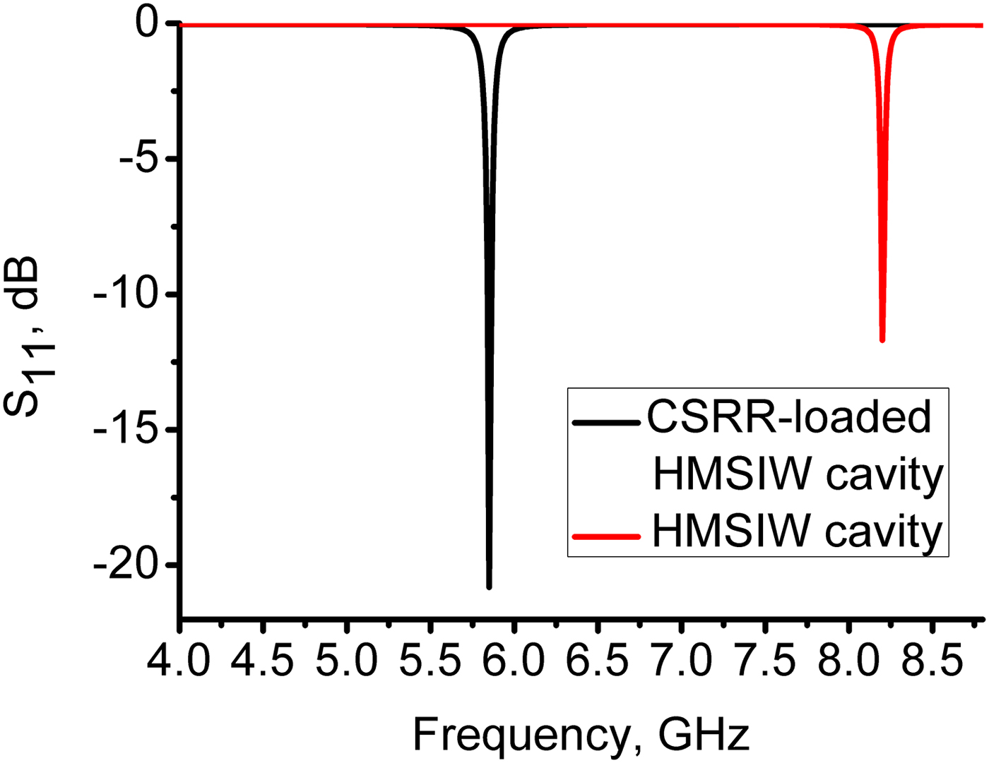
Fig. 2. Simulated S 11 of the HMSIW cavity (without a CSRR) and CSRR-loaded HMSIW cavity.

Fig. 3. The E-field distribution: (a) the HMSIW cavity without a CSRR; (b) bottom of the CSRR-loaded HMSIW cavity at 5.82 GHz; (c) top of the CSRR-loaded HMSIW cavity; (d) bottom of the CSRR-loaded HMSIW cavity at 8.2 GHz.
To compare the humidity performance of the CSRR loaded HMSIW sensor and its SIW counterpart, two prototypes are designed and fabricated, as shown in Fig. 4. A vector network analyzer (VNA) (PNA N5244A, Agilent Technologies, USA) is used to measure the S 11 of the resonator. The microwave experimental system has been calibrated by using an open-short-load mechanical calibration kit (Agilent E8056D) before testing. The output power level of the VNA is set to 0 dBm. Figure 5 shows the simulated and measured S 11 of the CSRR-loaded HMSIW resonator. The measured resonance frequency is observed at 5.79 GHz. There is a small difference between the simulated and measured results because of the printed circuit board fabrication resolution.
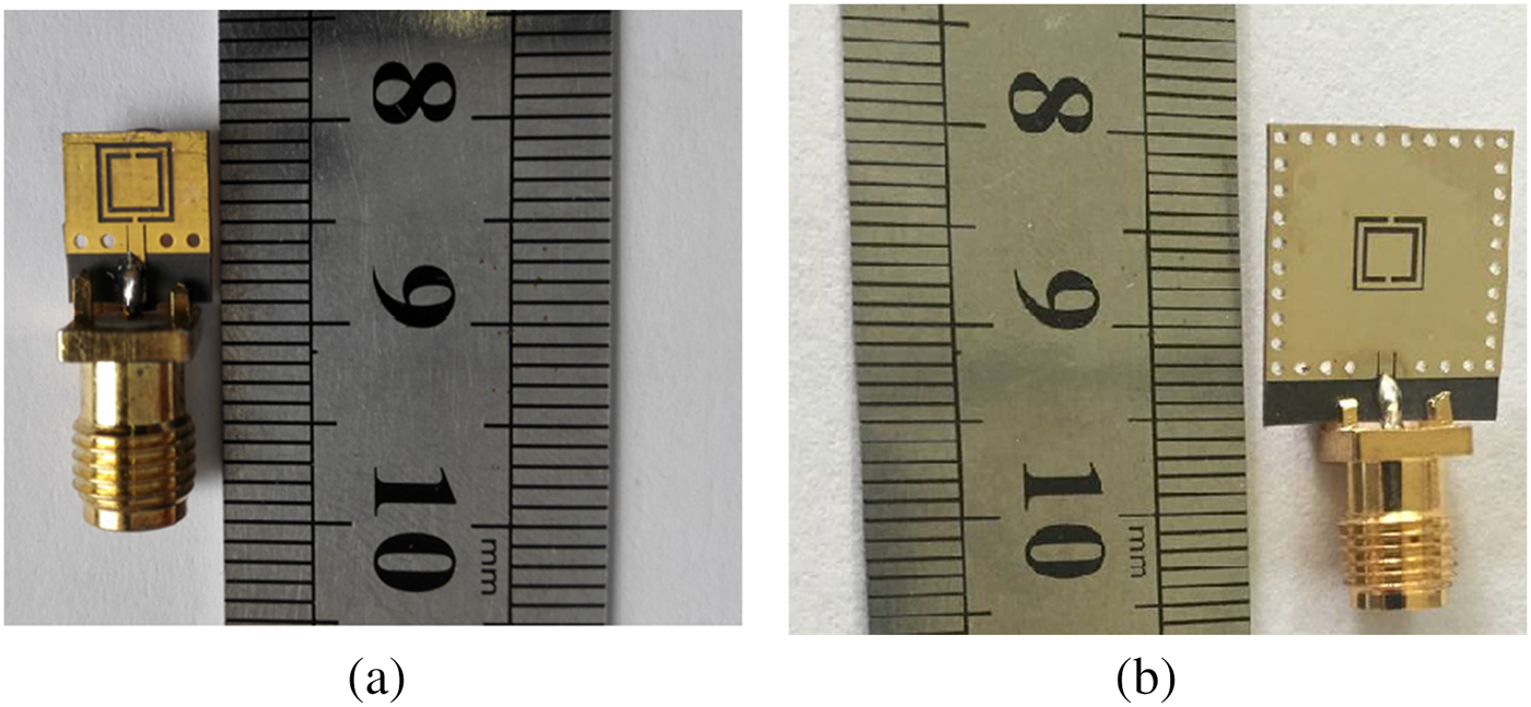
Fig. 4. Images of the fabricated sensors: (a) the HMSIW sensor; (b) the SIW sensor.
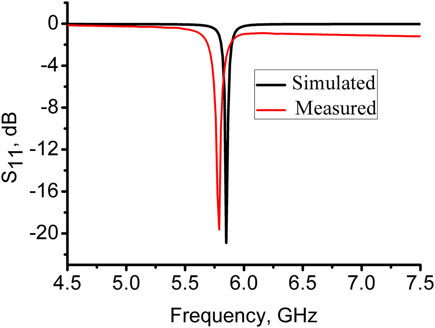
Fig. 5. Simulated and measured S 11 of the fabricated sensor.
III. HUMIDITY MEASUREMENT
The humidity experimental setup is given in Fig. 6. The port 1 of the VNA is directly connected to the fabricated sensor through a soft coaxial cable. Saturated LiCl, MgCl2, Mg(NO3)2, NaCl, KCl, KNO3, and K2SO4 solutions at 25°C were approximately yield ~11.3, 32.8, 54.3,75.3, 84.3, 92.5, and 97.3% relative humidity (RH) levels, respectively. Due to the presence of moisture inside the slots of the CSRR, the effective permittivity of the dielectric will be changed, resulting in a frequency shift for the resonator. It is noted that the experiment is repeated for 4 days and the readings are obtained under the same experimental conditions.
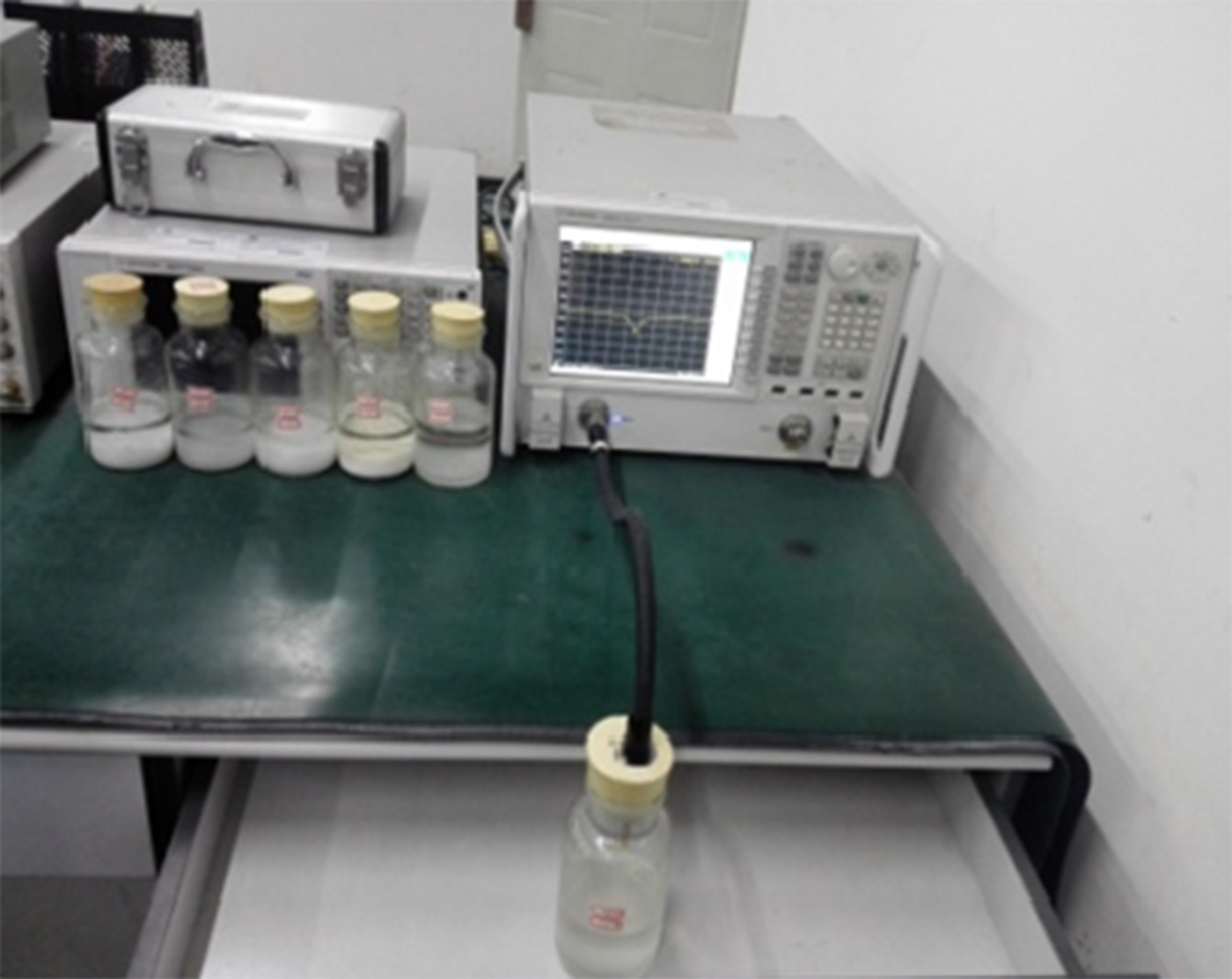
Fig. 6. Humidity experimental setup.
IV. RESULTS AND DISCUSSION
The measured S 11 of two sensors as a function of frequency at different humidity levels are plotted in Figs 7(a) and 7(b). It can be clearly found that the measured resonance frequency of each sensor decreased with the RH level increased. Also, the peak magnitude of |S 11| of the sensor decreased with increasing RH. The measured humidity sensitivity S of the HMSIW resonator is given by [Reference Chang, Kim, Kim and Yoon12]
 $$S = \left \vert {\displaystyle{{\Delta f_r} \over {\Delta \% RH}}} \right \vert$$
where △f r is frequency shift and △%RH is the corresponding change of RH. Figure 7(c) plots the frequency response of the two sensors with the RH levels. Examination of the figure shows that the frequency shift of the HMSIW sensor is obviously larger than that of the SIW sensor in the range 11.3–97.3%RH. According to equation (3), the measured humidity sensitivity of the HMSIW sensor and SIW sensor are 312 kHz/%RH and 239 kHz/%RH in the RH range of 11.3–84.3%, respectively. When humidity changed from 84.3 to 97.3%, the HMSIW sensor can provide high humidity sensitivity up to 5.82 MHz/%RH that is about five times compared with the SIW humidity sensor. This result indicates that our sensor is more suitable for the high RH detection since it has large sensitivity at high RH region. The enhanced sensitivity of the HMSIW sensor can be interpreted as follows: (1) the introduction of the CSRR structure can effectively increase the numbers of adsorbed water molecules on the surface of the substrate, resulting in the increase of the effective dielectric constant [Reference Matbouly, Boubekeur and Domingue5]. Thus, the equivalent capacitance of the shunt LC resonant tank will increase with increasing RH levels; (2) the fringe E-field of the HMSIW sensor can also increase the equivalent capacitance of the LC resonant tank. These two factors will significantly decrease the resonant frequency of the CSRR-loaded HMSIW humidity sensor, i.e. the increase of the humidity sensitivity.

Fig. 7. Measured results of the fabricated sensor at different humidity levels: (a) S 11 for the HMSIW sensor; (b) S 11 for the SIW sensor; (c) frequency response of the fabricated HMSIW and SIW sensors.
Humidity hysteresis characteristics of the proposed sensors were also measured. The sensors were first placed in the RH-increasing environment for water absorption, and then exposed to the RH-decreasing environment for water desorption. Figure 8 plots the humidity hysteresis curves of two sensors. It can be found that the humidity hysteresis effect is not patent in the range of 11.3%RH–97.3%RH for the HMSIW sensor. The inset of the Fig. 8(a) shows the small difference between the curves of the adsorption and desorption. From the Fig. 8(b), it can be seen that the maximum humidity hysteresis of the SIW sensor occurred at nearly 92.5%RH and was about ~3%RH. Obviously, the HMSIW sensor has the lowest humidity hysteresis than the SIW sensor. This result indicates that water molecules adsorption and desorption do not introduce excessive dielectric losses for the HMSIW sensor.

Fig. 8. The humidity hysteresis: (a) HMSIW sensor; (b) SIW sensor.
Previous microwave humidity sensors with or without sensing material were reported in the literature. Table 1 lists the humidity performance comparison between the proposed evanescent mode HMSIW sensor and other microwave humidity sensors. It can be observed that most of the RF or microwave humidity detection structures with sensing material achieved sensitivity in the order of several hundreds of kHz/RH. While our proposed sensor without any sensing material can provide the advantages of high sensitivity, wide humidity detection range, and compact size. This indicates that the proposed compact sensor is more convenient for passive sensing applications.
Table 1. Comparison of microwave sensors for humidity sensing.

V. CONCLUSION
In this paper, we proposed a miniaturized evanescent mode HMSIW humidity sensor loaded with a CSRR. Without any sensing material, the sensor which has a compact size of 0.17λ g × 0.17λ g can provide high humidity sensitivity up to 5.82 MHz/%RH at high RH region (>84.3%). The proposed structure can be a good candidate to implement high sensitivity microwave passive sensors for humidity sensing applications.
ACKNOWLEDGEMENTS
This work was supported by the National Natural Science Foundation of China (grant no. 61401047).
 Chang-Ming Chen was born in Sichuan, China. He received his MS degree from the School of Physical Electronics, University of Electronic Science and Technology of China, China in 2006. He is currently pursuing his Ph.D. degree at the School of Physical Electronics, University of Electronic Science and Technology of China (UESTC). His current research interests include microwave and millimeter-wave sensors.
 Jun Xu was born in Sichuan, China. He is currently a Professor in the School of Physical Electronics, University of Electronic Science and Technology of China (UESTC). His current research interests include microwave and millimeter-wave circuits and system.


