Introduction
Antennas used for ultra-wide band (UWB) applications must provide satisfactory radiation properties over the UWB spectrum (3.1–10.6 GHz) and simultaneously achieve good time domain performance. UWB antennas are also required to be compact and easy to fabricate in order to be suitable for various applications [Reference Hamalainen, Hovinen, Hentila, Oppermann, Hamalainen and Iinatti1]. In this context, the family of printed monopole antennas has gained great attention in research community due to their attractive merits such as small planar profile, wide bandwidth, omni-directional radiation pattern, low dispersion, low cost, and ease of fabrication [Reference Ray2]. However, the design of UWB antennas is a challenging task. Instead of arbitrarily designing the dimensions, shape, and topology of a UWB antenna, an automatic design of optimum planar shape of the antenna by using optimization methods is more preferable to obtain the best design. Optimization of UWB antennas is to find an optimal antenna configuration which should satisfy one or more of the above mentioned performance requirements.
In UWB antenna optimization, the design of antenna shape has been formulated as an optimization problem that has fitness function which is derived based on the desired performance parameters. A numerical solution of the optimization problem starts from an initial set of design variables and proceeds through a number of iterations. For each iteration, the optimization algorithm computes new updates of the design variables in order to improve the fitness function which leads to achieve the best one.
Antenna optimization methods can be classified into three groups: sizing, shape, and topology optimization based on parameterizing the design domain. In sizing optimization, only the cross-section of the structure is optimized by a set of design variables such as width and length in that structure. Many antenna designs have been proposed based on this optimization over the past several years. Combination of the genetic algorithm (GA) with finite difference time domain (FDTD) method [Reference Kim, Yoon, Kim and Choi3]; microgenetic algorithm with FDTD method [Reference Jie, Yang and Sun4]; self-organizing multi-objective GA with Ansys HFSS software [Reference Silva, Lins, Martins, Barreto and d'Assuncao5] are the few techniques used to optimize the UWB antennas.
In shape optimization, the design variables characterize the shape of the boundary of a reference domain. For this optimization, among the many techniques, combination of particle swarm optimizer (PSO)-driven spline-based shaping approach with a method of moments (MoM)-based electromagnetic (EM) simulator, developed at the Electromagnetic Diagnostic Laboratory (ELEDIA) of the University of Trento [Reference Lizzi, Viani, Azaro and Massa6]; Jumping Genes optimization algorithm with IE3D EM simulation software [Reference Yang, Ng, Yeung and Man7]; Pareto efficient global optimization (ParEGO) algorithm with Computer Simulation Technology Microwave Studio (CST MWS) EM simulation software [Reference John and Ammann8] are few techniques that are demonstrated in the literature.
In the topology optimization, the desired space is divided into small cells and the material distribution of each cell is taken as a design variable and the presence or absence of materials is denoted as either 1 (metal) or 0 (vacuum/air), respectively [Reference Sigmund and Maute9]. By using optimization technique, the material distribution of each cell is controlled simultaneously in each iteration step and updated based on the evaluation of objective function in order to approach the final optimum design. Since, the antenna radiation characteristics are depending on the current distribution in the geometry of the antenna [Reference Balanis10], topology optimization has drawn considerable attention in the field of antenna design.
The material distributive approach of topology optimization combined with evolutionary optimization algorithms for the design of UWB antennas have been discussed in many literature. Ding et al. [Reference Ding, Jin and Geng11] applied the mixed model of 2-D GA and FDTD for optimizing the UWB antenna and band-notched UWB antenna [Reference Ding, Jin, Geng, Wu and Yang12]. Zhao et al. [Reference Zhao, Shen and Wu13] designed the mirror symmetric topology material distributive optimized UWB antenna using double population GA (DPGA) and FDTD. Mirhadi and Soleimani [Reference Mirhadi and Soleimani14] implemented the parallel binary particle swarm algorithm (BPSO) and discrete green function method with asymmetric and mirror symmetric material distributive topologies for optimizing the dual-band antennas and same has been extended to design the UWB antennas with stable radiation pattern [Reference Mirhadi, Komjani and Soleimani15]. In all these articles, the metallic patch is divided in to uniform size cells. Teirab et al. [Reference Teirab, Jervase and Mneina16] proposed non-uniform segmentation of radiating patch for UWB antenna optimization with mirror symmetric topology. The antenna is designed using CST MWS software co-simulated with MATLAB used for GA implementation through ActiveX control. Chen and Chiu [Reference Chen and Chiu17] implemented the multi-objective topology optimization with non-uniform pixelation in order to design the miniature UWB antenna with enhanced pulse preservation. This has been done by combining Ansoft High Frequency System Simulator (HFSS) for antenna simulation with MATLAB for controlling the strength Pareto evolutionary algorithm 2 (SPEA2) optimization algorithm.
The meta heuristic algorithms [Reference Bianchi, Dorigo, Gambardella and Gutjahr18] are the better alternative to the traditional optimization approach for heuristic problems with less or insufficient information and less computational requirement. These algorithms can be local or global search algorithms. Hill climbing, simulated annealing, etc., are popular algorithms for local search methods. Ant colony optimization, PSO, and GA are popular algorithms for global search methods. Another most important category is single solution or population-based solution. Single solution-based strategies evaluate single candidate solution per generation. Simulated annealing is the most popular single solution based strategy. This strategy is mostly implemented for local searching and is convenient for parallel computing. Populationbased solution on the other hand evaluates multiple candidate solutions per generation. This is most convenient for parallel computing. GA and PSO are most popular techniques and can be implemented with or without swarm intelligence. Swarm intelligence-based algorithms [Reference Kennedy and Eberhart19] use collaborative self-organized agents to move toward the global best solution. PSO is the best example for this type of algorithm [Reference Banks, Vincent and Anyakoha20, Reference Banks, Vincent and Anyakoha21]. GA does not use swarm intelligence, but they use crossover and mutation to pass down genetic information of best solution to next generation. In order to operate in binary problem spaces, BPSO where the particle position value is either 0 or 1 is used [Reference Kennedy and Eberhart22].
Generally, the antenna's performance metrics are computed and analyzed by solving the Maxwell's equations. Now, there are many accurate numerical methods that allow Maxwell's equations to be solved effectively, such as the MoM, the finite element method, the FDTD method, and so on. For designing the wide-band antenna, the time domain method is more suitable than the frequency domain method because the broad bandwidth characteristics are obtained through only one simulation run of the time domain technique code [Reference Jie, Yang and Sun4]. Therefore, FDTD method is more suitable for the design of UWB antenna.
In this paper, the UWB antenna is optimized by using material distributive topology with improved BPSO and FDTD. In our work, to facilitate the implementation of UWB antenna design optimization, in BPSO, the velocity of each particle is calculated by using complete set of bits of particle position vector where as single bit in original BPSO and the V-shaped transfer function is employed to transform all real values of velocities to values in the interval [0,1] instead of Sigmoid transfer function. Also, to evaluate the fitness function of each particle parallely using FDTD, each particle is termed as an object and called with unique object identifier. FDTD simulation variables and functions for each particle are inherited from FDTD base class. Section “Optimization of UWB antenna” discusses about improved BPSO, FDTD, and implementation aspects. The results and discussion are presented in section “Results and discussion”. In section “Conclusion”, the conclusion is presented.
Optimization of UWB antenna
The material distributive topology design is used in this work for a complete layout optimization of the radiating patch geometry of UWB monopole antenna. In this method, the radiating patch geometry is described by dividing the patch surface into small, equally sized elements. The material property of each element is directly mapped into a binary value of 0 or 1 which indicates air or conductor, respectively. Each element's binary values are arranged as a binary string consisting of series of 0's and 1's. Each binary string will lead to an arbitrary structure for antenna's radiating patch and the performance can be improved by automatically varying the values in the binary string without increasing the overall volume or manufacturing cost of the UWB monopole antenna. Finally, the optimal binary string satisfying the desired performance is explored over a number of iterations. The implementation of this method requires a full-wave EM solver such as FDTD for analyzing the performance of the antenna and a meta-heuristic optimization algorithm for determining the optimum antenna structure. An improved BPSO algorithm is used in this work.
Improved BPSO
The BPSO was proposed by Kennedy and Eberhart [Reference Kennedy and Eberhart22] to allow PSO to operate in binary problem spaces. In this version, particles could only fly in a binary search space by taking values of 0 or 1 for their position vectors. The roles of velocities are to present the probability of a bit taking the value 0 or 1. Each particle in BPSO should consider the current position (X i), the current velocity (V i), the distance to their personal best solution(pbest i) and the distance to the global best solution (gbest) to modify its position. In original BPSO, the calculation of the value of velocity of each particle is based on a single bit and Sigmoid transfer function  $(({1})/({1+e^{-v_i^k(t)}}))$ is used to map a continuous search space to a binary one [Reference Kennedy and Eberhart22]. The original version of BPSO suffers trapping in local minima [Reference Mirjalili and Lewis23], so in this article some modifications have been introduced in order to overcome this problem. Here, the velocity of each particle is calculated based on the complete set of bits corresponding to the particle position vectors as in equation (1) [Reference Mohamad, Omatu, Deris, Yoshioka, Zainal, Omatu, Rocha, Bravo, Fernandez, Corchado, Bustillo and Corchado24]. The V-shaped transfer function as in equation (2) is employed to transform all real values of velocities to probability values in the interval [0,1] [Reference Mirjalili and Lewis23]. After converting velocities to probability values, position vectors of particles could be updated with the probability of their velocities as given in equation (3).
 $$ \eqalign{V_i = & \,w {\ast} V_i+c_1 r_1 {\ast} (\,pbest_i - X_i) \cr & + c_2r_2 {\ast} (gbest-X_i),} $$
where w is the inertia weight. Initially, the value of this weight is chosen as 1, and for every iteration, it is damped with the value of 0.95. c 1 and c 2 are the acceleration constants in the interval [0, 2]. r 1 and r 2 are the random values in the range [0, 1]. pbest i and gbest represent the best previous position of the i th particle and the global best position of the swarm (all particles), respectively.
 $$T(V_i)=\left \vert{\displaystyle{2} \over {\pi}}\arctan\left({\displaystyle{\pi} \over {2}}V_i\right)\right \vert. $$
Position of particles can be updated as follows,
 $$ x_i^k (t + 1) = \left\{ {\matrix{ 0 & {If\;rand < T\left( {v_i^k (t + 1)} \right)} \cr 1 & {If\;rand \ge T\left( {v_i^k (t + 1)} \right)} \cr } } \right., $$
 where  $ v_i^k$ is the velocity of k th bit of i th particle.
Parallelization in BPSO can be done by two methods [Reference Alba25]. First parallelization of computations, where computation of each particle is performed in parallel. Second parallelization of population, in which population is split in different groups and computation can be done in parallel as shown in Fig. 1. We chose later one which is more suitable for less complex implementation. Parallel computation can be done in two ways, i.e centralized and distributed. Centralized parallel algorithm is suitable for simplicity. In our model, in every iteration, the particles in the population are grouped and a centralized scheduler allocates workers for each group. Worker is responsible for doing the computations necessary to evaluate the new position of the particle and update the global best solution. They work independently. Number of workers depends on the computational capacity of the system. If the worker finishes the work, it will return to the worker pool, then the scheduler may allocate it to the new waiting group if any or just wait for next iteration.
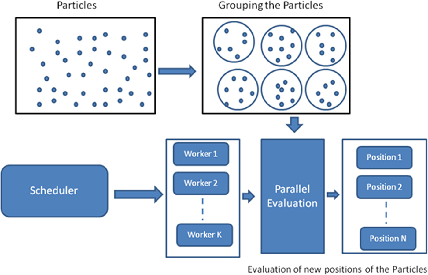
Fig. 1. Parallel computation of PSO.
FDTD
The FDTD method, introduced by K. Yee in 1966, is the most popular technique used to solve a variety of EM problems [Reference Yee26]. This method is implemented by discretizing the Maxwell's curl equations in the space and time domains. The Yee's FDTD algorithm divides the problem geometry into spatial grid where the electric and magnetic field components are arranged at certain discrete positions in space based on leapfrog manner. Also, it solves the Maxwell's equation in time at discrete time instances. The update equations for electric and magnetic fields based on central finite difference are derived from Maxwell's curl equations as explained in detail in many literature [Reference Taflove and Hagness27, Reference Elsherbeni and Demir28]. These updated equations allow to compute magnetic and electric field values with a recursive procedure in time and space. Also, in order for the FDTD simulation to work properly, the spatial and time discretization increments should satisfy the Courant Friedrichs Lewy (CFL) stability condition [Reference Taflove and Hagness27]. Since the computational storage space is finite, FDTD problem space needs to be truncated by special boundary conditions such as absorbing boundary conditions (ABCs) [Reference Taflove and Hagness27]. These boundary conditions are used to presume that the EM waves propagate continuously beyond the computational space. The imperfect truncation of the problem space will create numerical reflections which will corrupt the results [Reference Taflove and Hagness27]. Among many ABCs available in the literature, the convolutional pefectly matched layer (CPML) proposed by Roden and Gedney [Reference Roden and Gedney29] assumes a special medium surrounding the problem space to create the wave impedance matching conditions. The CPML approach is also independent of material medium and can be extended for dispersive media, anisotropic media, or non-linear media [Reference Elsherbeni and Demir28, Reference Roden and Gedney29]. For these reasons, this method is adopted in this work. In antenna problems, the aim is to find the radiated fields that are far away from the antenna. With the FDTD technique, the direct evaluation of far field needs excessively large computational domain which is not practically possible. Therefore, Huygens surface equivallence theorem has been implemented at the output boundary to obtain near-to- far field transformation [Reference Taflove and Hagness27, Reference Elsherbeni and Demir28].
Implementation
Topology-based antenna optimization problem is a NP- hard problem. It is a global optimization problem. It has large solution space which demands populationbased strategy. This leaves us the two most popular candidate algorithms to solve the problem which are PSO and GA. Primary need of algorithm for our solution is less computation, less complexity, and cooperation among population. PSO is the most possible candidate for these requirements. Figure 2 shows the flow chart for the overall implementation of the proposed model. The first step of the FDTD algorithm is to initialize the field values, source, updating coefficients, boundary conditions and CPML coefficients. After the initialization, the improved parallel BPSO algorithm is used to find the optimal topology for UWB antenna.
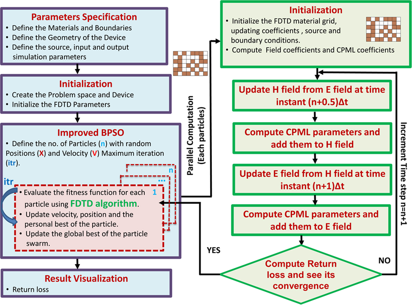
Fig. 2. Implementation of improved BPSO with FDTD method for UWB antenna optimization.
The fitness function is computed by using FDTD parallely for all the particles and it is defined as:
 $$ Fitness=F_1+F_2+F_3. $$
Here, F 1, F 2, and F 3 represent the fitness functions of three different frequency regions. Let δ be the sample spacing of the frequency (f). For frequency region 1 to (3.1 − δ) GHz with N 1 as the number of frequency components in this region, fitness function F 1 can be expressed as,
 $$ F_1={\displaystyle{1} \over {N_1}}\sum_{\,f=1\,{\rm GHz}}^{(3.1-\delta)\,{\rm GHz}} S_1(\,f). $$
Where,
 $$S_1 = \left\{ {\matrix{ {-5\,{\rm dB,}} & {If\;S_{11}(\,f) \ge -5\,{\rm dB}} \cr {S_{11}(\,f),} & {If\;S_{11}(\,f) \lt -5\,{\rm dB}.} \cr } } \right.$$
Here, S 11(f) is the return loss over frequency f.
For frequency 3.1–10.6 GHz with N 2 as the number of frequency components in this region, fitness function F 2 can be expressed as,
 $$ F_2={\displaystyle{1} \over {N_2}} \sum_{\,f=3.1\,{\rm GHz}}^{10.6\,{\rm GHz}} S_2(\,f). $$
Where,
 $$S_2 = \left\{ {\matrix{ {-12\,{\rm dB,}} & {If\;S_{11}(\,f) \le -12\,dB} \cr {S_{11}(\,f),} & {If\;S_{11}(\,f) \gt -12\,dB.} \cr } } \right.$$
For frequency (10.6 + δ) to 12 GHz with N 3 as the number of frequency components in this region, fitness function F 3 can be expressed as,
 $$ F_3={\displaystyle{1} \over {N_3}}\sum_{\,f=(10.6+\delta)\,{\rm GHz}}^{12\,{\rm GHz}} S_3(\,f). $$
Where,
 $$S_3 = \left\{ {\matrix{ {-5\,{\rm dB,}} & {If\;S_{11}(\,f) \ge -5\,{\rm dB}} \cr {S_{11}(\,f),} & {If\;S_{11}(\,f) \lt -5\,{\rm dB}.} \cr } } \right.$$
Parameters of the particles are inherited from base FDTD object. These parameters are updated independently. This object structure facilitates the parallel computation.
For each iteration, after the evaluation of the fitness function using parallelization for all the particles, pbest i is identified as the i th particle's best position. If current iteration pbest i is better than previous itreation's pbest i, then the pbest i will be updated. The best particle's pbest i value will be updated to gbest. As discussed in section “Improved BPSO”, the velocity and position of each particle will be updated using (1) and (3), respectively. This will continue as long as the algorithm converges. After the convergence, the return loss results of the optimal UWB antenna topology is visualized and verified.
Results and discussion
In the FDTD analysis, the step sizes for x, y, and z directions are 0.5, 0.5, and 0.4 mm, respectively. To satisfy the CFL stability condition, the time step Δt is taken as 0.75 ps. The total computation domain consists of the antenna geometry, excitation source, the 10 layers of air boundary, and the 10 layers of conventional PML which is used as the absorbing boundary. Unit amplitude Gaussion pulse is used to excite the antenna at the end of the feed line. The total time steps of 5000 is taken here but it is limited by the convergence of return loss.
The initial design of antenna consists of a 50Ω microstrip feed line with (3 mm × 10 mm), two steps of (9 mm × 1.0 mm) and (12 mm × 1.5 mm), a rectangular patch of (16 mm × 12 mm), and a ground plane of (24 mm × 8 mm). The overall dimensions of the antenna is 24 mm × 28.5 mm. The antenna is printed on a FR4 epoxy substrate of relative permittivity 4.4 and 1.6 mm thickness.
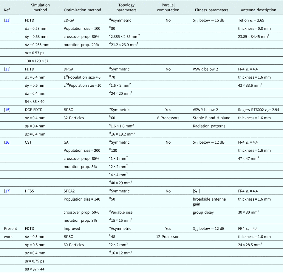
The rectangular patch is divided into 8 × 6 cells, each cell size being 2 mm × 2 mm as shown in Fig. 3. Each cell is mapped as a bit and hence the 48 cells in the patch is represented as a 48-bit binary string. Each combination of 48 bits is considered as a particle of BPSO, wherein the cell with metal is considered as “1” and with vacuum as “0”. In the improved BPSO implementation, a total of 60 particles are selected for optimization of the antenna. For parallel computation implementation, the optimization process utilizes 12 parallel processors. Therefore, for a 60-particle swarm, FDTD simulation is repeated five times within each iteration of optimization to evaluate the fitness function of all particles. The good converged optimization is obtained after 170 iterations and convergence curve is plotted in Fig. 4. These computations were carried out on a 64-bit system with 12-core 2.10 GHz CPU and 16 GB RAM. The total time and the memory usage for optimization are about 200 h and 10 GB, respectively. The optimized UWB antenna after the convergence is shown in Fig. 5. The methods and parameters used for topology optimization-based UWB antenna design is summarized in Table 1. From this, it is observed that the area used for topology optimization and antenna overall dimensions are small compared with others.

Fig. 3. Initial Antenna Layout - Pixelated radiating patch geometry used in the optimization of UWB antenna.
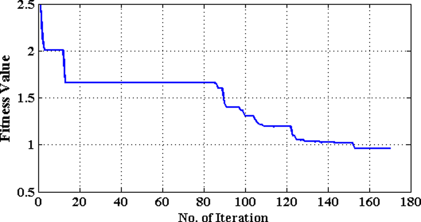
Fig. 4. Convergence curve of fitness value in the optimization of UWB antenna.
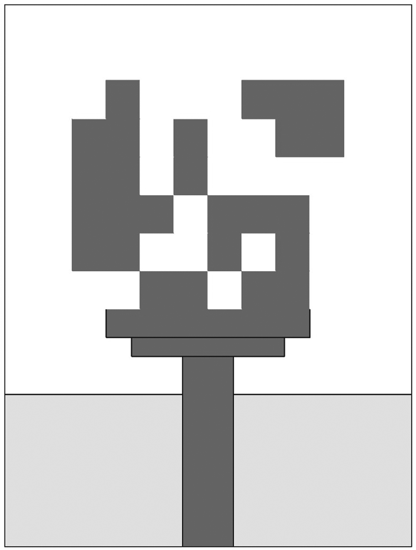
Fig. 5. Optimized UWB antenna design.
Table 1. Summary of the methods and parameters for UWB antenna design using topology optimization

a Type of topology.
b Number of bits used to represent the topology.
c Size of a cell.
d Dimension of topology design domain.
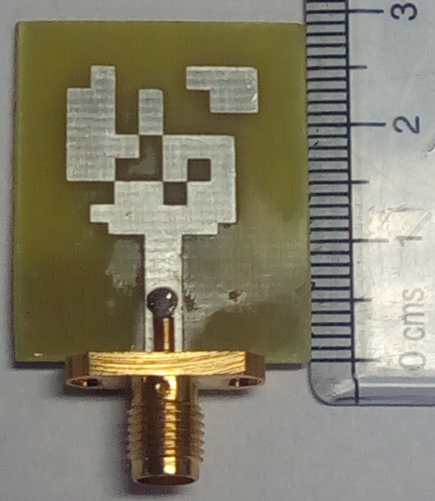
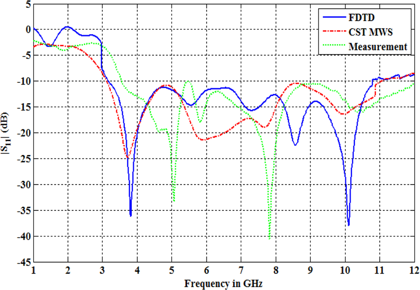
The fabricated prototype of the optimized UWB antenna is shown in Fig. 6. The measurement of the S parameters is carried out by using Keysight ENA series E5071C vector network analyzer over the frequency range of 1–12 GHz. Calculated and measured return loss (S 11) of the optimized antenna are shown in Fig. 7. The S 11 obtained for the optimized antenna simulated using CST microwave simulation tool is also plotted for comparison. It can be seen that the designed antenna shows the desired return loss performance over the frequency range of interest, using FDTD calculations, CST simulation, and from the practical measurement.

Fig. 6. The fabricated prototype of the optimized UWB antenna.

Fig. 7. The calculated, simulated, and measured return loss of the optimum UWB antenna.
The gain and radiation efficiency of the optimally designed UWB antenna obtained from CST simulation are shown in Fig. 8. The peak gain of the antenna varies from 2.216 to 4.875 dBi in the 3–11 GHz frequency range. The radiation efficiency is maintained above 80%. The current distribution of the antenna at frequencies 3.5, 6.5, and 10.5 GHz are shown in Fig. 9. At 3.5 GHz, the current gets distributed over the entire optimized structure of the patch. As the frequency increases, the current is traveled only in the edges of the patch.
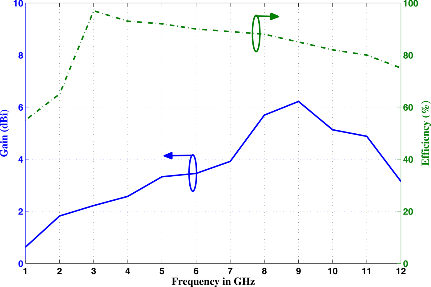
Fig. 8. The simulated gain and efficiency of the optimum UWB antenna.
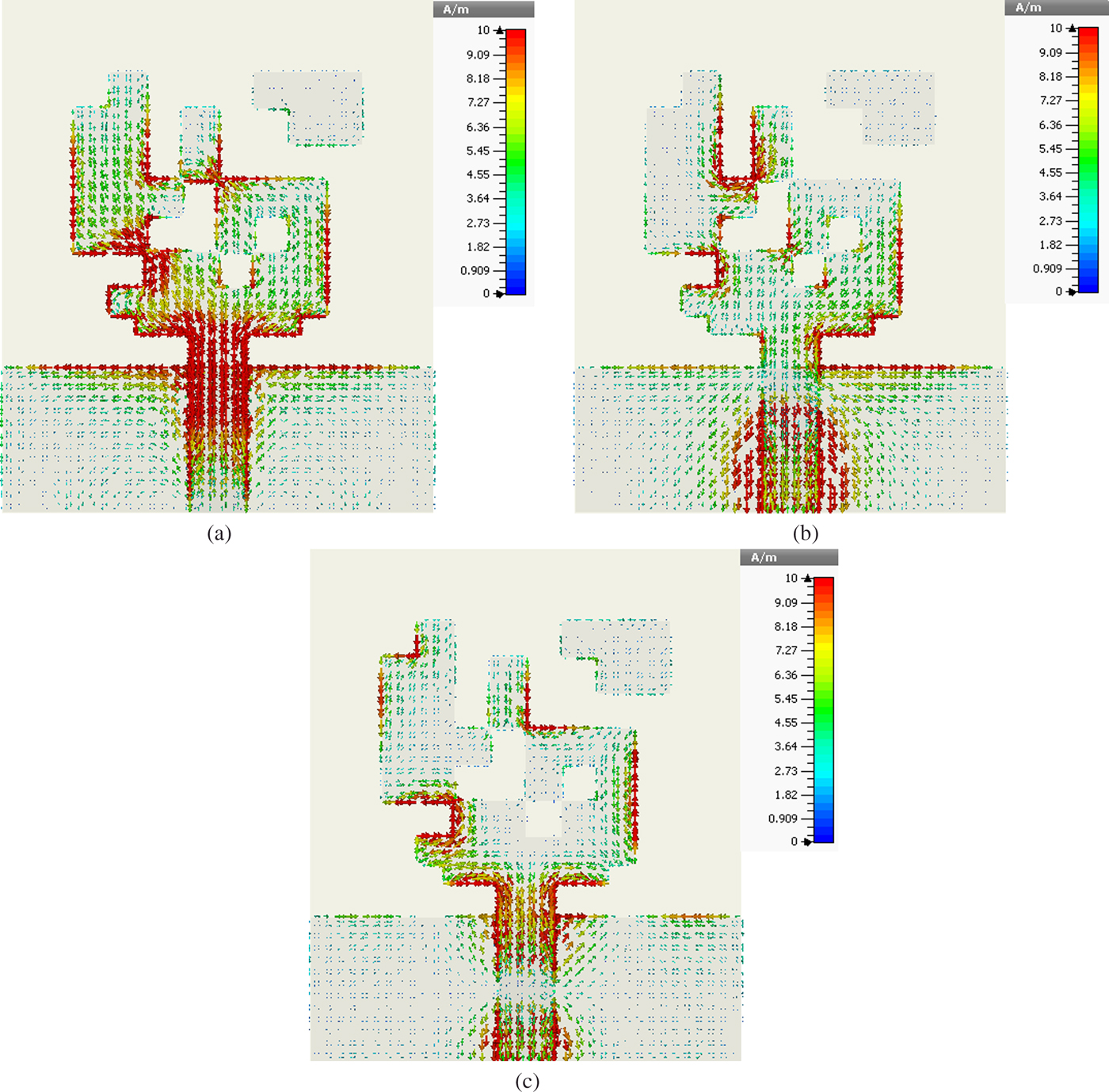
Fig. 9. Simulated total current distribution of the optimum UWB antenna at different frequencies (a) 3.5 GHz, (b) 6.5 GHz, and (c) 10.5 GHz.
In IR-UWB systems, the information should be transmitted and received in the form of very narrow pulses with minimal distortion. The system fidelity factor (SFF) which is derived from the system transfer function (S 21) is used to measure the correlation between the received signal and transmitted signal [Reference Quintero, Zurcher and Skrivervik30]. Hermitian processing method is used to convert the measured S 21 to time domain impulse response [Reference Hamalainen, Hovinen, Hentila, Oppermann, Hamalainen and Iinatti1,Reference Chandra and Meenakshi31]. S 21 is measured by keeping two identical antennas at a distance of 200 mm away from each other and connected to the ports of Agilent ENA series vector network analyzer. In the S 21 measurement, the transmitted antenna is stationary and the received antenna is rotated in steps of 20°. The S 21 is also obtained from the CST simulation.
In order to calculate the SFF, two different transmitted pulses such as fifth-order Gaussian pulse with pulse parameter α = 60 ps and sine-modulated Gaussian pulse with a carrier frequency of 6 GHz, pulse parameter α = 350 ps are considered. From Fig. 10, it is observed that for both input pulses, SFF values obtained from simulation and measurement are almost linear with above 75% and the input pulses experience minimal distortion in all angular directions around the antenna.
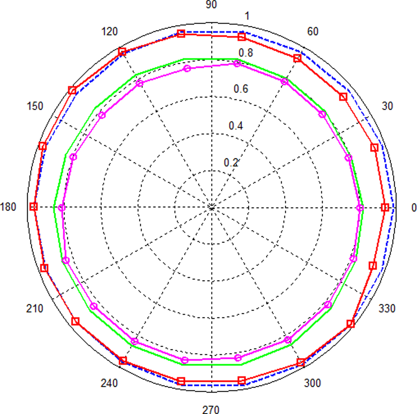
Fig. 10. SFF values of the optimum UWB antenna: simulated fidelity patterns for fifth-order Gaussian pulse (solid green line), sine-modulated Gaussian pulse (dashed blue line), and measured fidelity patterns for fifth-order Gaussian pulse (circle marked magenta line), sine-modulated Gaussian pulse (square marked red line).
Conclusion
The optimized UWB antenna is designed based on material distribution topology by using improved BPSO with FDTD. The implementation of the improved BPSO algorithm combined with the FDTD method is highly efficient due to their discrete nature. Since all particles within an iteration are evaluated independently, the fitness function evaluation of particles can be performed simultaneously and in parallel by using FDTD. Effectiveness of this method is verified by CST simulation. The optimized antenna structure has been fabricated and experimentally validated the simulation results. Also, the optimized antenna has relatively stable peak gain with less variation and good radiation efficiency over the UWB frequency band.
Acknowledgement
This work has been done from the grant received from Visvesvaraya PhD scheme for Electronics and IT.
 Thilaga Shri Chandra A P received the B.E degree in Electronics and Communication Engineering from the College of Engineering Guindy, Anna University, Chennai, India and M.E (Communication Systems) from Anna University, Chennai, India in 2003 and 2007, respectively. She is currently working toward her doctorate degree at the College of Engineering Guindy, Anna university, Chennai, India. She has published nearly 10 papers in national and international conferences. Her main research interest includes UWB antennas for WBAN applications, computational electromagnetics and optimization.
 Senthilkumar L received the B.E degree in Electronics and Communication Engineering and M.E (Communication Systems) from Anna University, Chennai, India in 2009 and 2012, respectively. He is currently working toward his doctorate degree at the College of Engineering Guindy, Anna university, Chennai, India. He has published nearly 10 papers in national and international journals and conferences. His current research interests include cross-layer design, evolutionary algorithms, optimization, machine learning and cooperative communication.
 Meenakshi M Professor, Department of Electronics and Communication Engineering, Anna University Chennai, Guindy campus, Chennai-600025; (e-mail: meena68@annauniv.edu), India, completed B.E (Honours), M.E, and Ph.D in the years 1989, 1992, and 1998, respectively. She has been a faculty at Anna University, Chennai, since 1998. She is a member of IEEE, ISTE, and Anna University Research gate. She has published nearly 35 national and international journal papers and also more than 60 national and international conference papers in the field of optical communication and networks, and wireless communications. Currently her research works are focused on Green mobile communication, EMP effects, wireless body area networks, radio over fiber network optimization, etc.