Introduction
Nowadays, several European, North-American and Asian countries are becoming more interested in the development and expansion of their high-speed railways (HSR) networks, which have been prioritized by several governments as the motor of their local economy [Reference Henríquez BL and Deakin1]. However, trains designed to travel at speeds up to 400 km/h open new technological challenges in terms of safety and security.
In one hand, since HSR networks are considered critical infrastructures, the surveillance of the railway perimeter is a high priority requirement for avoiding uncontrolled intrusions that may endanger the security. Besides, it has been recently exposed the necessity of developing new perimeter surveillance systems that deal with the negligent or malicious usage of consumer drones. Current systems are based on fence sensor monitoring [2], detecting impacts of objects and jumps over the fence, surveillance cameras [3], or active radars [4] that autonomously monitor, detect, and alert users of moving objects in protected areas. Nevertheless, these surveillance systems show certain limitations in HSR scenarios: fence sensors cannot detect aerial vehicles such as drones; surveillance cameras are severely affected by the weather and light conditions, and, due to their narrow field of view to achieve long-range detection, they usually require an excessive time to cover the whole volume under surveillance, not suitable for the detection of high-dynamic targets; mid-range active radars are not appropriate for large longitudinal areas because the deployment of several devices along the rails would entail a considerably high cost.
On the other hand, an accurate system for train and railway monitoring is needed to avoid accidents and to optimize the use of the infrastructure. For this reason, the installation of the European Rail Traffic Management System is currently mandatory in European HSR, but further research should be carried out to develop robust systems that provide the railway managers with real-time information about the tracks and to detect possible obstacles on the rail. To that end, the integration of a Ku-band radar on the head of the train is proposed in [Reference Liu, Yang, Zhang and Deng5].
The next-generation communication systems deployed in railway scenarios and based on the Long-Term Evolution (LTE) standard are commonly referred to as LTE-Railway (LTE-R) systems. The solution proposed in this paper attempts to fulfill both aforementioned surveillance and monitoring tasks by using the downlink LTE-R signal as illumination of opportunity in order to develop a distributed passive multistatic radar system. As shown in Fig. 1, the receiving nodes of the sensor network can be implemented by using Commercial Off-The-Shelf Sofware Defined Radios (SDR), considerably reducing the deployment cost of the system, which in turn makes use of the already deployed LTE-R infrastructure. Besides, this system does not need spectrum allocation, do not interfere with other communication systems and is easily scalable.
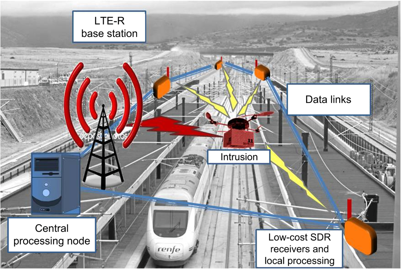
Fig. 1. Diagram of the LTE-R-based passive multistatic radar approach proposed in this paper: SDR nodes deployed along the railway received the LTE-R reference signal and its reflections on the targets, apart from other multipath components. The target detections performed locally in each receiving node are sent to a central processing node where data fusion and target tracking are performed.
Passive radars systems have been developed for target detection with analog [Reference Colone, Bongioanni and Lombardo6] and digital [Reference Fang, Yi, Wan, Liu and Ke7] signals, and for train monitoring using the Global System for Mobile communications-Railway (GSM-R) [Reference Chetty, Chen and Woodbridge8]. However, the novelty of the proposed system, whose preliminary design and analysis were presented in [Reference Blázquez-García, Casamayón-Antón and Burgos-García9], is the use of passive multistatic radar techniques based on LTE-R signals to provide surveillance and monitoring services to HSR scenarios. In this paper, the design and preliminary results of this system based on simulations are presented.
This paper is organized as follows. The section “Analysis of LTE-R as illumination of opportunity” presents an overview of the LTE-R specifications and downlink waveform, and an analysis of its ambiguity function based on measured signals. In the section “LTE-R-based passive radar system design”, the design of the proposed passive radar system is described, including both the hardware architecture and the signal and data processing. The estimation of its maximum detection range and simulation results of the detection of moving targets are presented in the section “Estimation of covered area and simulation results”. Finally, concluding remarks are drawn in the section “Conclusions”.
Analysis of LTE-R as illumination of opportunity
LTE-R specifications and downlink waveform
Nowadays, GSM-R system is widely implemented in HSR networks. However, due to its limited capacities, it is foreseen a short time until the end of its lifetime. Therefore, in view of the performance and maturity level of LTE, LTE-R has been proposed as the next communication system for HSR, since it is able to accomplish with all the new operational needs, be compatible with the standard 4G LTE network, and coexist with GSM-R [Reference He, Ai, Wang, Guan, Zhong, Molisch, Briso-Rodriguez and Oestges10]. This LTE variant for railway scenarios is based on the LTE standard and it uses a subset of the LTE parameters in order to guarantee the specific requirements of HSR scenarios in terms of mobility, reliability, and capacity. In this way, LTE-R systems have linear coverage along the track instead of cellular deployment and, preferably, use modulations with low-order constellations and lower frequency bands in order to extend coverage and reduce handovers. In spite of its maturity level, LTE-R is still in a deployment and test phase [Reference Solanki11, Reference Zhou, Tao, Salous, Liu and Tan12].
LTE-R network should achieve not only the safe operation of trains, but also advanced railway services provided in the future. Thus, it shall comply with the following operational needs: high-speed movements up to 500 km/h, broadband wireless transmission for real-time video, low latency up to 500 ms, network reliability and availability and quality of service [Reference Choi, Song and Kim13]. In order to attain all these requirements, the system parameters of LTE-R are listed in Table 1.
Table 1. LTE-R system parameters

Uplink LTE-R is based on single-carrier frequency division multiple access (SC-FDMA), whereas downlink LTE-R signals use orthogonal frequency division multiplexing (OFDM) with 15 kHz subcarrier spacing, and each subcarrier is modulated using quadrature phase-shift keying (QPSK) or 16-quadrature amplitude modulation (16-QAM).
Based on the physical layer of the LTE standard [14], the frame structure of downlink LTE-R signals using frequency division duplex (FDD) and normal cyclic prefix is represented in Fig. 2. In order to demodulate the transmitted signal, the physical layer includes two synchronization signals, the primary synchronization signal (PSS) and the secondary synchronization signal (SSS), which are transmitted twice in each frame, and reference signals (RS), which are used for channel estimation and equalization. The frame structure of the downlink LTE-R signal with the insertion of cyclic prefixes in guard intervals and pilot subcarriers give rise to ambiguities when applying the range-Doppler cross-correlation processing in passive radars, which may compromise their performance by masking real targets or causing false alarms. For this reason, since communication signals are not optimized for radar use, it is important to analyze the suitability of downlink LTE-R signals as the illumination of opportunity for passive radar by means of the ambiguity function.
Fig. 2. Frame structure of downlink LTE-R signals using FDD and normal cyclic prefix.
Besides, the usage of a digital signal allows us to obtain a noise-free reference signal by demodulation and subsequent remodulation of the received direct signal transmitted by each LTE-R base station in order to improve the actual performance of the passive radar system. This reconstruction of the reference signal is based on the physical layer standard of LTE-R and it includes the processing steps displayed in Fig. 3.

Fig. 3. Reconstruction processing of downlink LTE-R signal based on demodulation and subsequent remodulation in order to obtain a noise-free reference signal for passive radar usage (PSS, primary synchronization signal; SSS, secondary synchronization signal; RS, reference signals; S/P, serial to parallel; P/S, parallel to serial; FFT, Fast Fourier Transform; IFFT, inverse FFT; M-QAM, M-ary quadrature amplitude modulation).
Figure 4 shows the normalized power spectrum of a downlink LTE-R transmission measured by an SDR equipment. In this case, the transmitted signal is allocated in a 10 MHz-bandwidth channel at the 800 MHz band. However, the actual bandwidth of the signal does not occupy the whole channel due to the use of guard bands to avoid interfering the adjacent channels. When using downlink LTE-R signals as the illumination of opportunity, this bandwidth reduction decreases the bistatic range resolution of the passive radar system. Besides, the power spectrum of the received signal shows a ripple due to the frequency-dependent channel response, which should be equalized before demodulation using the reference signals transmitted in the LTE-R frame.
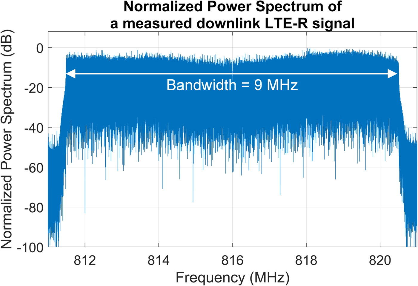
Fig. 4. Normalized power spectrum of a measured 10 MHz-channel downlink LTE-R signal at the 800 MHz band.
As an example of the output of the demodulation processing, Fig. 5 shows the constellation diagram for the Physical Downlink Shared Channel (PDSCH) of a measured downlink LTE-R signal after channel equalization. The 4-QAM detector, the subsequent remodulation of the physical layer channels and the addition of synchronization and reference signals based on LTE-R standard allows us to obtain a noise-free reference signal to be cross-correlated with the surveillance signals in the passive radar signal processing, described in the following section.
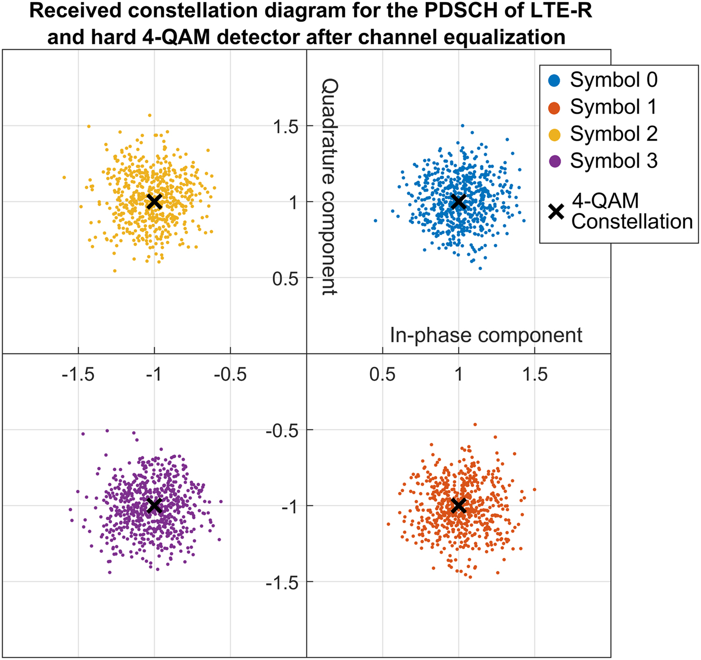
Fig. 5. Received constellation for the PDSCH of LTE-R after channel equalization. The color of the points indicates the output of the hard 4-QAM detector.
Self ambiguity function analysis of downlink LTE-R signals
The best bistatic range and Doppler resolution achievable by each receiving node of the multistatic system can be evaluated in terms of the self Ambiguity Function (AF) of the downlink LTE-R reference signals, which represents the output of the matched filter. However, it should be noted that the current bistatic range and Doppler resolution is related to the bistatic geometry between the target and each transmitter-receiver pair [Reference Baker, Griffiths and Papoutsis15].
The range-Doppler AF χ(τ, f d) of a signal of opportunity s(t) is given by
 $$ \chi (\tau,f_{d}) = \left \vert \int\nolimits_{-\infty}^{\infty}s(t) \cdot s^{*}(t - \tau) \cdot e^{-j2\pi f_{d}t} \cdot dt\right \vert ^{2}, $$
where τ is the time delay and f d is the Doppler frequency.
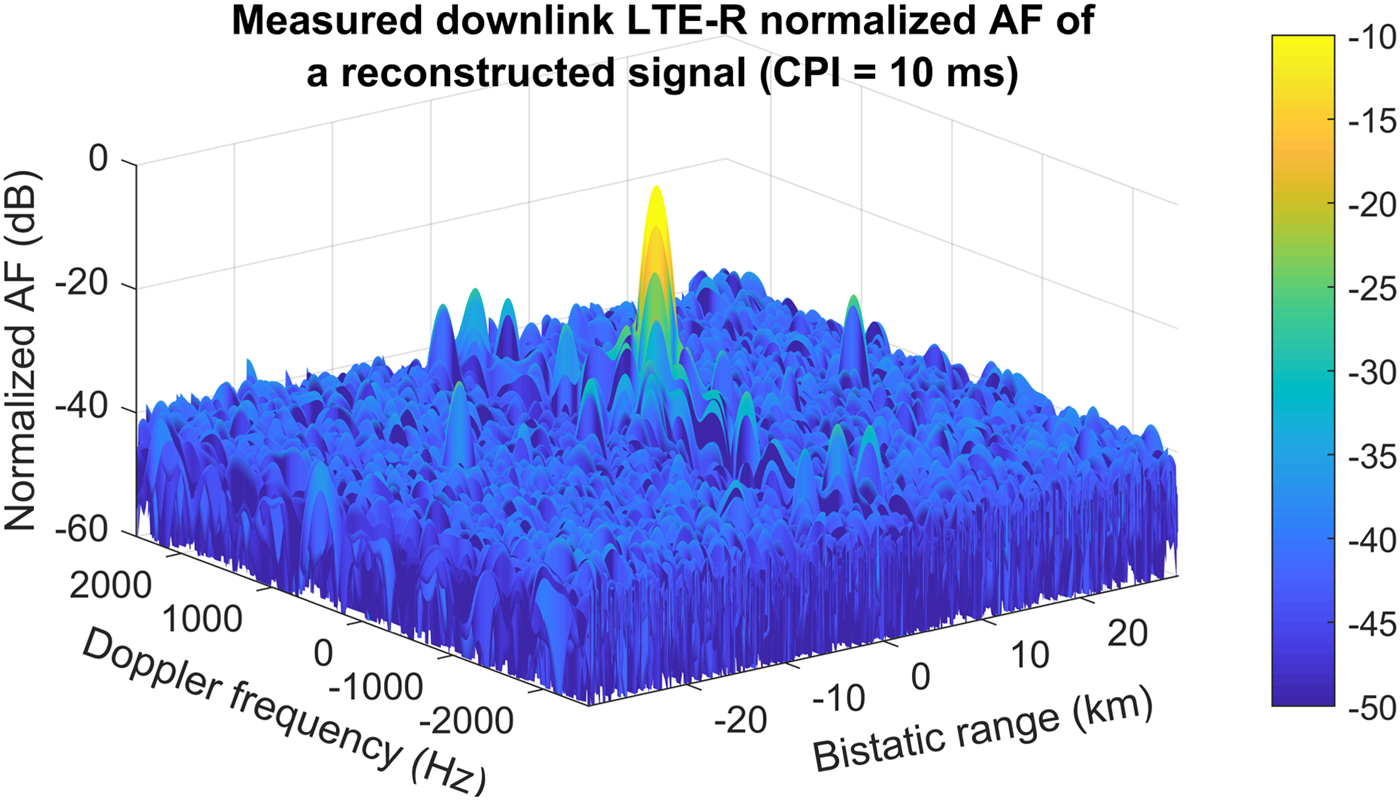
Based on a received downlink 10 MHz-channel LTE-R signal, Fig. 6 shows the range-Doppler AF computed after reference signal reconstruction using a coherent processing interval (CPI) of 10 ms. In order to reduce the sidelobe level, Hamming windows in the frequency and time domain have been applied. The obtained AF presents a near-thumbtack shape suitable for passive radar usage, but it shows several ambiguities due to the structure of the downlink LTE-R signal. In order to analyze the bistatic range and Doppler resolution and the sidelobe level of downlink LTE-R signals as illuminators of opportunity, the zero Doppler cut and the zero range cut of the computed AF for different CPIs are represented in Figs 7 and 8, respectively.

Fig. 6. Normalized Range-Doppler AF of a reconstructed 10 MHz-channel downlink LTE-R signal using a CPI of 10 ms and applying Hamming windows at frequency and time domain as a sidelobe reduction technique.

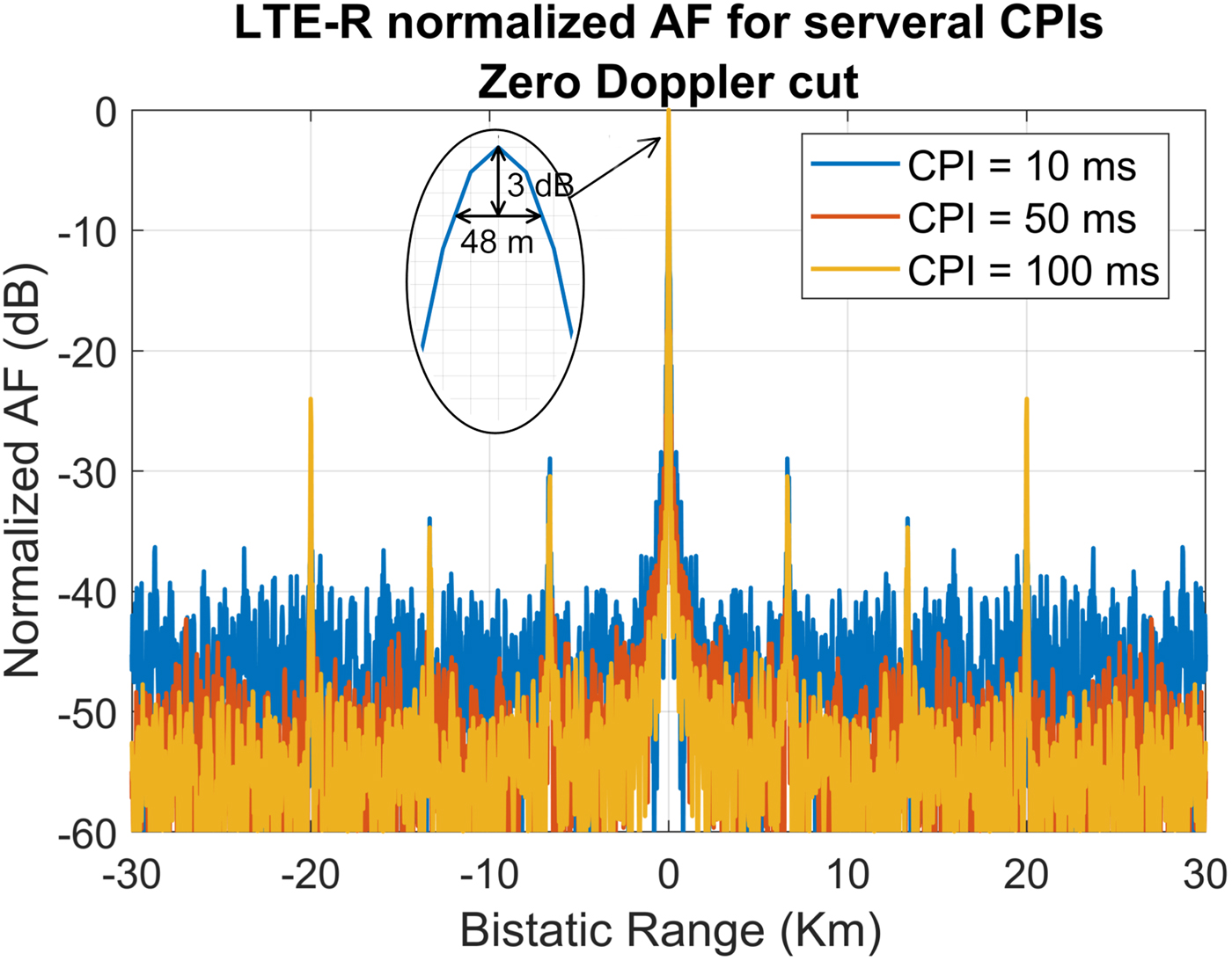
Fig. 7. AF zero Doppler cut of a reconstructed downlink LTE-R signal using different CPIs.

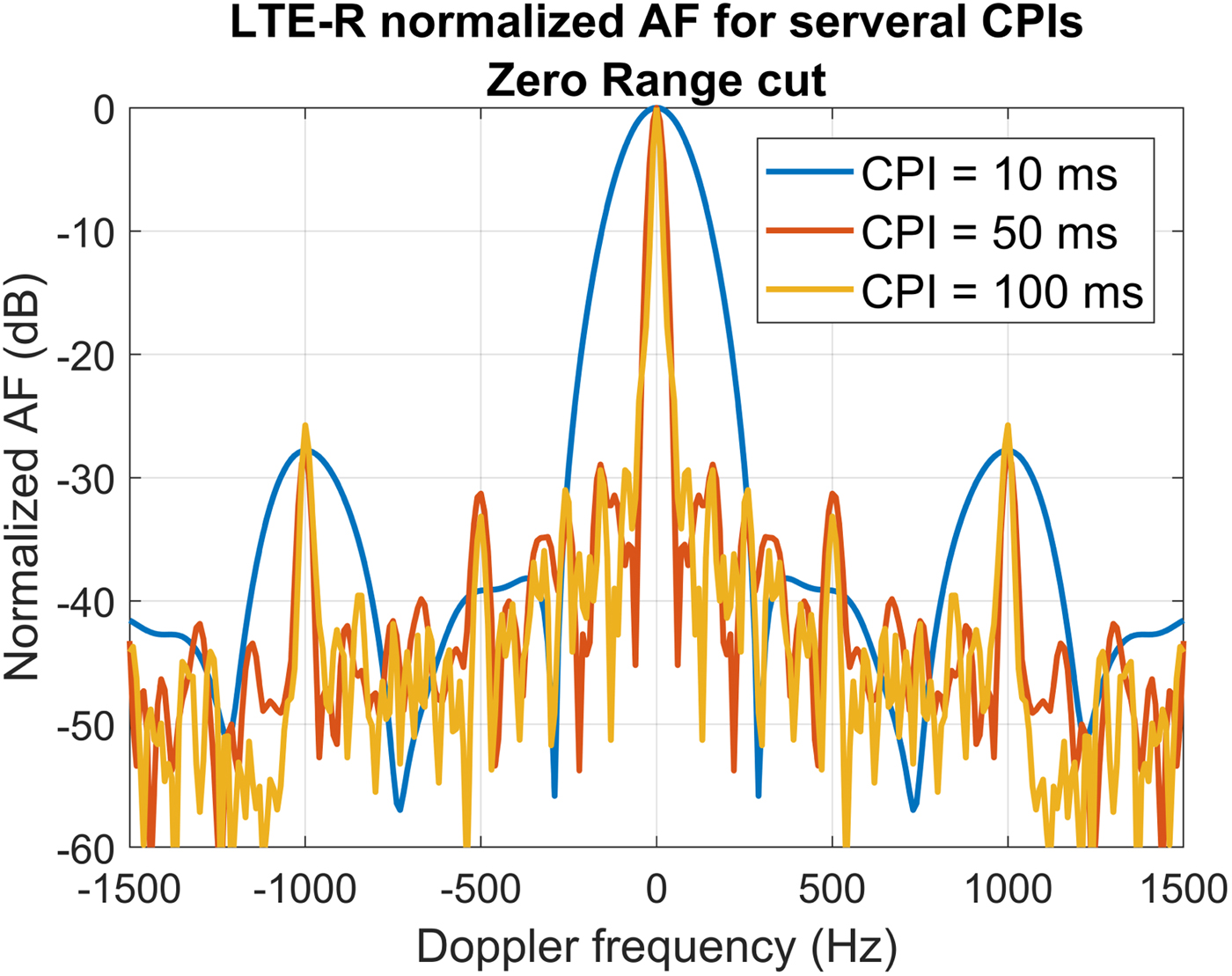
Fig. 8. AF zero Range cut of a reconstructed downlink LTE-R signal using different CPIs.
As it can be observed from the zero Doppler cut, the bistatic range resolution of the reconstructed downlink LTE-R signal is approximately 48 m for all the considered CPIs, which is in agreement with its approximate 9 MHz bandwidth and the resolution decrease due to the Hamming windowing. Besides, the floor level is decreased when increasing the CPI as it is expected due to the compression gain given by the product of the bandwidth and the CPI. However, a high range ambiguity appears at 20 km of bistatic range due to the cyclic prefix of the OFDM modulation. This ambiguity is related to the 66.7 μs useful symbol time (T u) of the LTE-R physical layer and it has a level approximately given by the ratio between the average cyclic prefix time ( $\overline {T}_{CP} = 4.77\,\mu {\rm s}$ for the normal cyclic prefix) and the useful symbol time (
 $\hbox{Ambiguity level} = 20\log _{10}(\overline {T}_{CP}/T_{u}) = -23\,{\rm dB}$). In our passive radar system, the considered instrumental range is shorter than 20 km in bistatic range, so this range ambiguity does not compromise its performance. Nevertheless, for other applications using LTE-R signals as illuminations of opportunity, it may be necessary to implement cyclic prefix blanking techniques [Reference Saini and Cherniakov16]. There also exist weaker ambiguities at 6.67 and 13.33 km due to the synchronization signals, which can be removed by processing the reconstructed signal.
Regarding the Doppler resolution, using a CPI of 10 ms, the zero range cut shows a −3 dB peak width of 172 Hz for the time domain Hamming windowed signal, which correspond to bistatic velocity resolutions of 64.5 m/s (employing the 800 MHz LTE-R band). This poor velocity resolution can be improved by using longer CPIs. This also increases the signal-to-noise ratio (SNR) of the targets and, accordingly, the maximum detection range of the system as long as the target coherence is maintained during the integration time. For this reason, in order to obtain a suitable velocity resolution and enhance detection range, a CPI of 250 ms is suggested for our passive radar system, which corresponds to a bistatic velocity resolution of approximately 10 km/h applying the Hamming window.
In the zero range cut of the AF, Doppler ambiguities appear at multiples of 1000 Hz due to the pulsed structure of the LTE-R signals, which are divided in subframes of 1 ms. However, these ambiguities are not significant for our system because they correspond to multiples of 1350 km/h in bistatic velocity, which are much higher than the bistatic velocities of the expected targets.
Therefore, taking into account the bistatic range and Doppler resolution, the floor level and the ambiguities estimated by means of the self AF of measured downlink LTE-R signals, it can be concluded that these signals are suitable for being used as illuminations of opportunity for passive radar systems. Besides, as LTE-R is based on LTE standard, the same conclusions can be drawn when generalized LTE downlink signals are used as the illumination of opportunity.
LTE-R-based passive radar system design
Hardware architecture
The geometrical deployment of the suggested passive multistatic radar system composed of two LTE-R transmitters of opportunity and two receiving nodes is depicted in Fig. 9, where the distance between two consecutive LTE-R base stations (eNodeB) is considered to be 10 km. A multistatic architecture is considered in order to improve target localization and target detection thanks to spatial diversity and multilateration [Reference Griffiths and Baker17, Reference Colone, Falcone, Bongioanni and Lombardo18]. Besides, this deployment can be scaled up along the railway track or include more receiving nodes to improve the system performance and coverage.

Fig. 9. Geometrical deployment of the suggested passive multistatic radar system (figure not to scale).
Each receiving node is based on a SDR device (National Instruments' USRP-2945) with four 80 MHz coherent receiving channels in order to apply digital beamforming techniques to receive the reference and the surveillance signals. The four antenna elements form a uniform linear array (ULA) with λ/3 spacing (12.5 cm for the 800 MHz LTE-R band) between them. Each antenna element has a 3 dBi gain and an omnidirectional radiation pattern.
As shown in Fig. 10, the SDR modules comprise the radio frequency (RF) front ends, the intermediate frequency (IF) stages, 14 bit analog-to-digital converters (ADC), and a field programmable gate array (FPGA), where the signal processing is performed to obtain the detections of the targets. The FPGA is connected through Peripheral Component Interconnect Express (PCIe), which controls the SDR device and performs the distributed data processing of the target plots generated by the signal processing. Finally, the computer transmits through a radio link the data to a central processing node, which performs the centralized data fusion and processing. Besides, this central processing node broadcasts synchronization signals through the radio link to the distributed receiving nodes.

Fig. 10. Hardware architecture of the passive multistatic radar system including the receiving nodes based on SDR devices and a central processing node.
Signal processing and multistatic data fusion
The block diagram of the signal processing performed in each receiving node of the proposed passive multistatic radar system is shown in Fig. 11. Firstly, digital beamforming is applied in order to acquire the two reference signals from the two LTE-R illuminators of opportunity and several surveillance channels from different directions. To this end, different simultaneous antenna beams with distinct nulls and main lobe directions are synthesized. As shown in Fig. 12, one reference beam is pointed to each LTE-R base station with a null in the direction of the other transmitter, whereas the overlapped surveillance beams have nulls in the direction of its associated transmitter of opportunity in order to reduce direct signal interference. Although, azimuth ambiguities arise from the ULA radiation patterns, these ambiguities are removed in the data fusion stage. To avoid blind zones in each transmitter-receiver pair, the signal received by the reference beam could also be used as a surveillance signal after direct signal and multipath cancellation, but it may have stronger interferences and, consequently, a lower target detection capability. However, even without using this approach, the whole 360° are covered with at least two transmitter-receiver pairs.

Fig. 11. Block diagram of the signal processing for the passive multistatic radar system with two LTE-R reference signal transmitted from two different eNodeB.
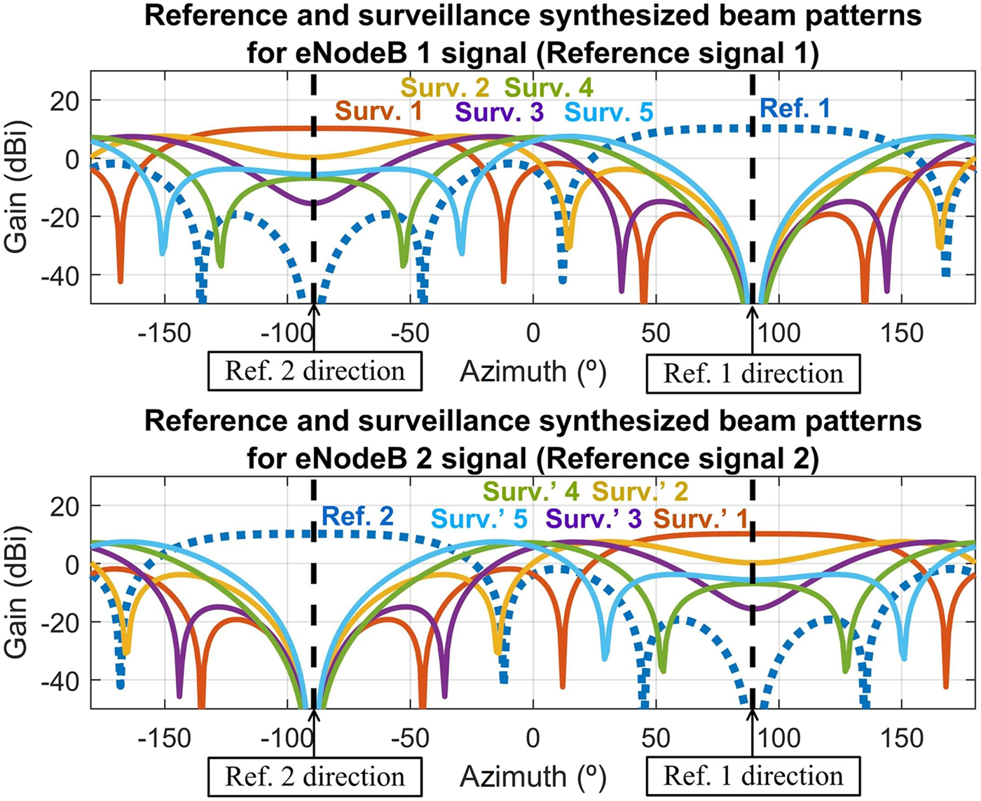
Fig. 12. Reference (dotted lines) and surveillance (solid lines) synthesized beams of the receiver node 1 for the two considered LTE-R eNodeB illuminators of opportunity.
Using the signals received with the two reference beams, the transmitted LTE-R signals are reconstructed based on the physical layer specifications of the communication standard. This approach, as suggested in [Reference Colone, Falcone, Bongioanni and Lombardo18], allows us to avoid the use of two dedicated receiving channel for the reference signals.
In each surveillance channel, considering both reconstructed reference signals, direct signal and multipath cancellation [Reference Lombardo, Colone, Melvin and Scheer19] is firstly applied to reduce direct path interferences and remove the echoes due to static clutter. Afterward, the windowed range-Doppler cross-correlation function between each surveillance channel and each reference signal is calculated. Taking into account the cellular deployment of LTE-R, in which two adjacent base stations use separate frequency channels, a low interference between the two reference signals is assumed. Therefore, being these reference signals almost orthogonal, the target echos from the two base stations can be separated in each receiving node.
Finally, a Constant False Alarm Rate (CFAR) [Reference Rohling20] detector is applied to each range-Doppler map and the plot extractor obtains the bistatic range, azimuth, and bistatic velocity estimations of the detected targets from the peaks of the cross-correlation functions.
Regarding data processing and data fusion, a two-stage tracking [Reference León-Infante, González-Partida, Blázquez-García and Burgos-García21, Reference Malanowski, Kulpa and Suchozebrski22] is implemented. This approach is divided into a first distributed tracking for each transmitter-receiver pair using the plots extracted by the signal processing and a second centralized tracking in Cartesian coordinates after the association of the output data from the distributed tracking of multiple transmitter-receiver pairs. Data association is based on a bottom-up processing [Reference Flöster and Rohling23], in which a finite set of possible target position inside the area of interest are considered and target positions are located at local minima of an error function calculated for each grid point. This error function is given by the quadratic sum of the distances between the considered grid point and the closest measurement of each transmitter-receiver pair. This approach allows us to reduce the global false alarm rate of the system and avoid ambiguities and ghost targets with an attainable computational complexity even in multi-target situations.
The suggested passive multistatic radar architecture and processing would be also applicable using other digital communication systems as the illumination of opportunity when adjacent base stations deployed along the rail tracks transmit pseudo-orthogonal signals, although the actual properties of the AF may change. Besides, the current widespread coverage of LTE system makes possible to use the suggested multistatic and scalable architecture to provide cost-efficient surveillance services or support to other surveillance systems in different application scenarios including airports, highways or other critical infrastructures.
Estimation of covered area and simulation results
In order to demonstrate the technical feasibility of the proposed surveillance and monitoring system in terms of its maximum detection range, Fig. 13 shows its estimated covered area based on the bistatic radar equation for the detection of cars, pedestrians, and small drones, using the parameters presented in Table 2 and considering that at least one transmitter-receiver pair achieves 90% probability of detection (P d) with 10−5 probability of false alarm (P fa).
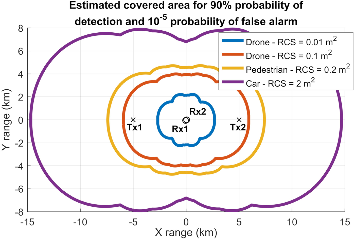
Fig. 13. Estimation of the covered area by the passive multistatic radar system for the detection of cars, pedestrians, and small drones considering that at least one transmitter-receiver pair achieves 90% probability of detection with 10−5 probability of false alarm.
Table 2. Parameters used for the estimation of the covered area

To estimate this covered area, eNodeB antenna radiation pattern of 30° beamwidth pointed over the rail track towards the receivers and the synthesized surveillance beams for each reference signal have been taken into account. Besides, it is assumed that the detection range is limited by thermal noise and not by the remaining direct signal or multipath interference after cancellation. The results show an estimated maximum detection range across the rail track of 7, 4.5, and 4 km for cars, pedestrians, and small drones of 0.1 m2 RCS, respectively. Further deployment of receiving nodes along the track would be required if drones of smaller RCS have to be detected by the system. The analyzed geometry is scalable and replicable along the track.
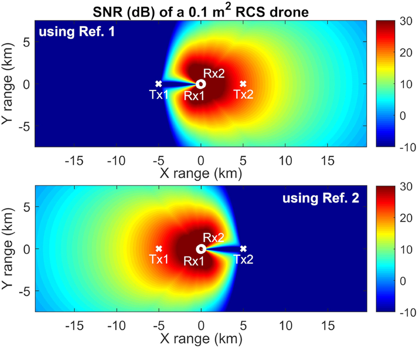
Figure 14 shows the obtained SNR of a small 0.1 m2 RCS drone [Reference Pisa, Piuzzi, Pittella, Lombardo, Genovese, Bloisi, Nardi, d'Atanasio and Zambotti24] for the receiver 1 when using each reference signal. Since the reference beams are not used as surveillance beams, blind zones appear for each transmitter-receiver pair but not when all transmitter-receiver pairs are considered. Therefore, the proposed system achieves a suitable covered area for the considered application of railway network surveillance and monitoring, even for the detection of small consumer drones, whose malicious usage may entail safety threats which are becoming a bigger concern of HSR managers.

Fig. 14. SNR in dB for the receiver 1 of a small drone with 0.1 m2 RCS when using the reference signal of the eNodeB 1 (top) and the reference signal of the eNodeB 2 (bottom).
Furthermore, a dynamic range requirement of 96 dB is estimated taking into account the direct signal power and the minimum detectable target echo power. This stringent dynamic range requirement is common in passive radar systems [Reference Malanowski, Kulpa, Kulpa, Samczynski and Misiurewicz25] .
High-speed trains are usually over 200 m long and made of metallic structures. Therefore, they act as extended scatters causing strong reflections which can be also detected by the suggested passive radar in order to monitor the traffic of trains. The usage of OFDM with cyclic prefix is robust against these strong multipath components, and the transmitted signals can be properly reconstructed to obtain the noise-free reference signals in spite of a train crossing the coverage area. However, these reflections cause ambiguities due to sidelobes and an increase in the noise floor level of the range-Doppler maps. Although a small area with reduced probability of detection for weak targets can appear near the crossing train in bistatic distance, these degrading effects are diminished thanks to the speed difference between high-speed trains and typical targets of interest and the good properties of the LTE-R ambiguity function in terms of sidelobe and noise floor levels.
Finally, in order to show the importance of applying accurate Direct Signal Interference (DSI) and multipath cancellation, Fig. 15 display the output of the Range-Doppler cross correlation between the LTE-R reference signal and a simulated surveillance channel when applying or not DSI and multipath cancellation techniques. Apart from the interference produced by the direct signal, the simulated surveillance channel contains several multipath components due to static clutter and the returns of two weak targets (Target 1 and Target 2), which are, respectively, 40 and 50 dB below the direct signal interference. When DSI and multipath cancellation is not applied, the returns from the targets are masked by the noise floor and they cannot be detected. However, when DSI and multipath components are suppressed, the targets can be detected, but they give rise to range ambiguities due to the signal structure, which can be removed by processing the reconstructed signal, and high Doppler side lobes, which can be decreased by applying further sidelobe reduction techniques.
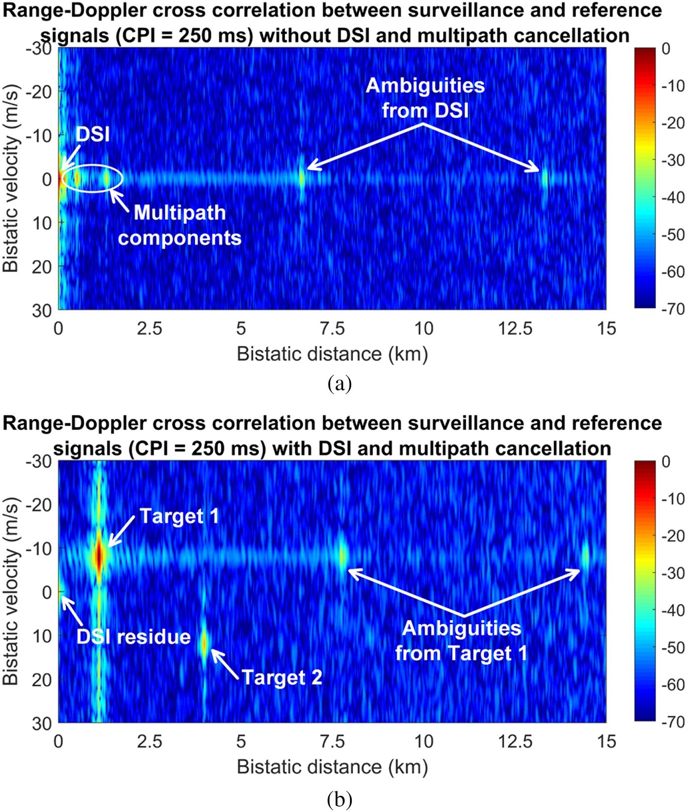
Fig. 15. Output of the range-Doppler cross-correlation function between the LTE-R reference signal and a simulated surveillance channel, which contains DSI, multipath components, and the returns of two weak targets: (a) without DSI and multipath cancellation, and (b) with DSI and multipath cancellation.
These results show the potential of using downlink LTE-R signals as the illumination of opportunity in passive radars, but field tests are being currently performed using commercial LTE eNodeB stations transmitting in the 800 MHz band with the typical modulation parameters for railway scenarios. In this way, the designed system will be experimentally validated to provide perimeter surveillance and monitoring of high-speed train networks.
Conclusions
A passive multistatic radar system based on LTE-R illumination of opportunity for the perimeter surveillance and traffic monitoring of HSR networks has been presented. The AF of downlink LTE-R signals shows good properties in terms of range and Doppler resolutions, sidelobe level and ambiguities. The multistatic and scalable system architecture is based on two LTE-R transmitter of opportunity and two SDR receiving nodes with four receiving channels. The signal processing performs a digital beamforming to synthesize different reference and surveillance beams, direct signal and multipath cancellation, and range-Doppler cross-correlations with the reconstructed reference signals. Regarding data processing and data fusion, a two-stage tracking and a bottom-up data association are implemented. Finally, the area covered by the system has been estimated and simulation results of target detection have been presented, showing promising performance for the detection of cars, pedestrians, and small drones. However, field tests are being performed to experimentally validate the designed system.
Acknowledgments
This work has been supported by the Spanish Ministry of Science, Innovation and Universities within the project TEC2017-87061-C3-1-R (CIENCIA/AEI/FEDER, UE). Rodrigo Blázquez-García is supported by the grant FPU15/01253 of the Spanish Ministry of Education.
Author ORCIDs
Rodrigo Blázquez-García 0000-0002-6471-4147
 Rodrigo Blázquez-García received the B.Sc. and M.Sc. degrees in Telecommunications engineering from Universidad Politécnica de Madrid (UPM), Spain, in 2014 and 2016, respectively, where he is currently working towards the Ph.D degree in the Microwave and Radar Research Group of the Signals, Systems and Radiocommunications Department as a recipient of a scholarship from the Spanish Ministry of Education. His research interests are in the area of radio frequency and radar systems, including signal and data processing techniques for passive radar systems.
 Jorge Casamayón-Antón received the B.Sc. and M.Sc. degrees in Telecommunications engineering from Universidad Autónoma de Madrid (UAM) in 2009 and from Universidad Carlos III de Madrid (UC3M) in 2014, respectively. Currently, he is working towards the Ph.D. degree in the Microwave and Radar Research Group of Universidad Politécnica de Madrid (UPM). His professional career is developed in Airbus Defence & Space as a Communication System Engineer where he is responsible for several aircraft connectivity research projects as well as the communication system architecture definition of the future combat aircraft.
 Mateo Burgos García received the Ingeniero de Telecomunicación and Ph. D. degrees from the Universidad Politécnica de Madrid, Madrid, Spain, in 1989 and 1994, respectively. Since September 1988, he has been with the Grupo de Microondas y Radar, Departamento de Señales, Sistemas y Radiocomunicaciones, Universidad Politécnica de Madrid, Madrid, Spain, where he is a Full Professor. His research activities include broadband digital receivers for spectrum surveillance and software-defined radios, broadband radars for low probability of interception and high-resolution applications, millimeter-wave radars, and synthetic aperture radar signal processing.