


Introduction
Wireless communications and internet services have been penetrating into our society and affecting our everyday life profoundly during the last decade far beyond any earlier expectations [Reference Wang1]. Several designs antennas used in internal mobile terminals applications with lightweight, low profile, and ease of fabrication [Reference Du, Gong and Fu2–Reference Wong and Chen20], such as monopoles [Reference Du, Gong and Fu2, Reference Hong, Kim, Park, Kahng and Choi3], loop antennas [Reference Chiu, Chang and Chi7, Reference Wong and Ma8], slot antennas [Reference Lee and Sun9], inverted-F shaped wire-form antennas (IFAs) [Reference Lin, Tang and Chang10], planar inverted-F antennas (PIFAs) [Reference Karkkainen11, Reference Kim, Lee, Cho and Lee12].
An internal meandered loop antenna is proposed in [Reference Lin and Wong5], the designed antenna has a symmetric metal-strip loop pattern and occupies a size of 27 × 43 × 7 mm3. The antenna can provide two wide operating bands to cover the desired frequency ranges of 98 MHz (866 −964 MHz) and 480 MHz (1667–2147 MHz) for the GSM900, DCS1800, and PCS1900 operation. On the other hand, a folded loop antenna is discussed in [Reference Chiu, Chang and Chi7], which is composed of a folded loop strip, two tuning strip line, and a pair of rectangular tuning elements. The designed antenna achieves the GSM850, GSM900, DCS, PCS, and UMTS (824–896, 880–960, 1710–1880, 1850–1990, and 1920–2170 MHz) operation and occupies a volume of 10 × 60 × 8 mm3. Also, a compact PIFA having two meander folded structures is demonstrated in the article [Reference Kim, Lee, Cho and Lee12]. The occupied volume of the antenna is 30 × 16 × 9 mm3 and is capable of operating at GSM900, DCS1800, and Satellite DMB (2605–2655 MHz) bands.
In addition, by using two methods parasitic strips and sleeve feed a planar meander monopole antenna with planar structure and area of 100 × 44 mm2 is reported in [Reference Zuo, Zhang and Yang13]. The antenna has a wide bandwidth covering 440−1350 MHz frequency ranges for the DVB-H, LTE, GSM850, and GSM900 operation in the mobile phone. The authors in [Reference Chiu, Teng and Wong15], introduced a shorted folded planar monopole antenna for GSM (890–960 MHz) and DCS (1710–1880 MHz) dual-band operations with a compact size of 5 × 10 × 40 mm3. Chia-Mei et al., in [Reference Peng, Chen, Hung, Shen, Chien and Tseng17], studied a simple planar monopole antenna with an area of 5 × 40 × 6 mm3, and consists of a metal-wire-cutting bended monopole antenna (BMA) fed by mini-coaxial cable jointly with a thin printed ground-line. The antenna operates over the CDMA (824–894 MHz), GSM (880–960 MHz), DCS (1710–1880 MHz), PCS (1850–1990 MHz), and WCDMA (1920–2170 MHz).
A printed strip monopole embedded with a chip inductor is discussed in [Reference Kang and Wong21]. The antenna comprises a chip-inductor-embedded longer radiating strip and a shorter radiating strip. The antenna occupies a size of 15 × 60 mm2 and can provide two wide operating bands to cover the frequency ranges of 140 MHz (824–964 MHz) and 640 MHz (1680–2320 MHz) which includes the GSM850, GSM900, DCS1800, PCS1900, and UMTS. As reported in [Reference Li and Wong22], an internal printed loop-type antenna is investigated. The antenna is composed of a driven monopole and a coupled strip. The antenna occupies a size of 20 × 45 mm2, yet supports two wide operating bands to cover the desired frequency ranges of 810–1180 MHz and 1540–2230 MHz for the GSM850, GSM900, DCS, PCS, and UMTS bands. In [Reference Chen, Lee, Lin, Cheng, Chiu and Chen23], a multi-arm coupled-fed monopole antenna is presented. The antenna consists of a monopole patch with a 50 Ω micro-strip feed-line and is printed on the front side of the substrate. The patch antenna operates a resonant mode at 2.66 GHz. On the back side of the substrate, a coupled-fed monopole with four arms and a ground plane are printed. The designed antenna occupies a size of 60 × 15 mm2 and can generate two wide operating bands to cover the frequency ranges of 720–1150 MHz and 1450–2200 MHz for the GSM850, GSM900, DCS1800, PCS1900, and UMTS applications.
The purpose of this paper is to design a low-profile planar monopole internal antenna for mobile phone applications which requires a small size of only 18.5 × 46 mm2 on the top surface of the FR4 substrate of area 46 × 88.5 mm2. As displayed in Fig. 1, the presented antenna has a compact structure, consists of multi-branches, tapered feeding line and two F-shaped slots in the ground plane. A prototype of the proposed antenna is fabricated and measured. In addition, the measured results demonstrate that the proposed antenna can provide two wide operating bands to cover the desired frequency ranges of 848–1152 MHz and 1736–3000 MHz. The obtained results show good performance in terms of antenna gain and radiation characteristics. Furthermore, the specific absorption rate (SAR) results of the presented antenna, placed at the bottom of the mobile phone, at the selected operating frequencies of 900, 1800, 1900, 2000, 2300, and 2450 MHz, are also evaluated and calculated according to the FCC standard (1.6 W/kg over 1 g tissue) and ICNIRP standard (2 W/kg over 10 g tissue). Three human head models have been implemented: a homogenous spherical head model, Specific Anthropomorphic Mannequin (SAM) phantom head and HUGO human head model provided by CST MWS. The configuration of the proposed antenna, parametric analysis, and results of the constructed prototype on the reflection coefficient, radiation characteristics, directivity, peak antenna gain, realized gain and efficiency are investigated and discussed in the following sections. The whole work of this paper used Ansoft HFSS software and CST Microwave studio to run all simulations and to calculate the SAR values.
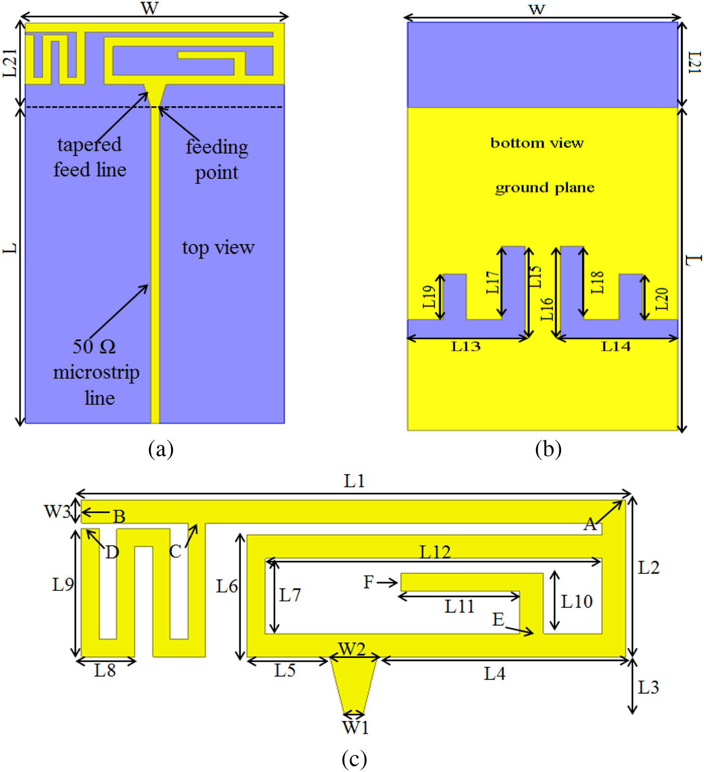
Fig. 1. Geometry of the proposed planar monopole internal antenna for GSM/DCS/PCS/IMT/ UMTS/WLAN/ISM/LTE operation in the mobile phones. (a) Front view. (b) Back view. (c) Dimensions of the metal pattern of the antenna.
Antenna configuration and design methodology
Antenna design geometry
The geometry of the proposed low-profile planar monopole internal antenna for GSM/DCS/PCS/IMT/UMTS/WLAN/ISM/LTE operation in the mobile phones is illustrated in Fig. 1. In this study, the design of the antenna is based on an FR4 substrate of thickness 0.8 mm with a relative permittivity of 4.4, a loss tangent of 0.02, a size of 46 × 88.5 mm2, and is used as the system circuit board. The developed antenna is formed by multi-branches (branch 1(A-B), branch 2(C-D) and branch 3(E-F)), tapered feed line and occupies a small area ungrounded region of only 18.5 × 46 mm2, and is printed on the top surface of the substrate. On the other side of the substrate, a limited ground plane with two F-shaped slots with an area of 46 × 70 mm2 is printed. The dimensions of the system circuit board and ground plane are reasonable for practical applications in the modern slim mobile phones.
A 50 Ω microstrip feed line with a width of 1.54 mm is used to excite the proposed antenna in the simulation and is located along the center of the ground plane. In order to achieve a better impedance matching at the feeding point, a trapezoidal shape of 5 mm length is used and connected between the microstrip line and antenna. The width of the trapezoidal shape changes linearly from 1.54 mm at the feeding point to 4 mm at the edge of the patch antenna.
In principle, the lengths calculated from the feeding point to the open end of each branch were chosen to approximately equal a quarter of a wavelength at the resonance frequencies. The total length from the feeding point to the open end of branch 1 is approximately 82.5 mm which is close to the one-quarter wavelength of the 900-MHz frequency in free space. Also, the length from the feeding point to the open end of branch 2 is selected to be about 123.5 mm, approximately one-quarter wavelength of 800-MHz frequency. These two branches are used to control the lower frequency band. In order to generate another resonant mode in the higher band, an additional branch (branch 3) is added at a proper position, the calculated length from the feeding point to the open end of the resonant branch (E-F) is about 33.2 mm which is approximately a quarter wavelength at 2.26 GHz. In addition, the three resonant branches are not independent but coupling with each other, so that they have to be optimized jointly to achieve the multiband operation. The effects of these branches on the generation of the resonant modes of the antenna's lower and upper bands are more clarified in Fig. 2 in the section ‘‘Design procedure of the proposed antenna’’, and in the section ‘‘Antenna configuration and design methodology’’.

Fig. 2. Simulated reflection coefficient for the proposed antenna, the corresponding antenna with a simple rectangular patch and trapezoidal shape (Case 1), the corresponding antenna with slots in the radiating element and branch 1(A-B) (Case 2), the corresponding antenna with the addition of branch 2(C-D) (Case 3)and the corresponding antenna with the addition of branch 3(E-F) and without F-shaped slots in the ground plane (Case 4).
Notice that, the main role of the two F-shaped slots inserted in the ground plane is to obtain a good impedance matching and a wide bandwidth in the lower and upper bands, Fig. 2 illustrates the effect of the two F-shaped slots, positioned symmetrically with respect to the microstrip line on the performance of the presented antenna. Furthermore, the effects of several important design parameters of the proposed antenna on generating the antenna's lower and upper bands will be analyzed in the section ‘‘Parametric study of the proposed antenna’’, and in the section ‘‘Antenna configuration and design methodology’’. The optimization design was carried out with the help of numerous simulations. Table 1 lists detailed of the optimized dimensions of the proposed antenna design. The simulation results are obtained using the commercial program Ansoft High Frequency Structure Simulator (HFSS) which is based on Finite Element Method (FEM) that is operated in the frequency domain for analyzing the behavior of the proposed model and determining suitable values of parameters.
Table 1. Optimized values for the geometric parameters of the proposed antenna (unit in mm).

Design procedure of the proposed antenna
The aim of this work is to design a low-profile planar monopole antenna for GSM/DCS/PCS/ IMT/UMTS/WLAN/ISM/LTE application. In order to analyze the design evolution of the proposed antenna, several important case antennas are given as follows. Figure 2 depicted the simulated reflection coefficient versus frequency of the proposed antenna and four cases antennas, the case with a simple rectangular patch and trapezoidal shape (Case 1), the case with slots in the radiating element and branch 1(A-B) (Case 2), the case with the addition of branch 2(C-D) (Case 3), and the case with the addition of branch 3(E-F) and without F-shaped slots in the ground plane (Case 4). Noted that these four cases (Case 1, Case 2, Case 3, and Case 4) are developed in order to obtain the optimized geometric of the presented antenna. All the corresponding dimensions of the four antennas analyzed in the figure are the same as those of the proposed antenna. According to the simulation results, a wide bandwidth of 1192 MHz (1120–2312 MHz) is obtained by Case 1. The resonant frequency of the fundamental mode is generated at around 1171 MHz in the Case 2. From the comparison of Case 3 and Case 2 in Fig. 2, the first resonant mode is shifted from about 1171 to 950 MHz. On the other hand, by adjusting the dimensions and position of branch 3, a third resonant mode is appeared at around 2.258 in Case 4.
According to the simulation data depicted in Fig. 2, the impedance matching and bandwidth of the antenna's lower and upper bands obtained in Case 4 (without slots in the ground plane) are not sufficient to cover the desired lower and upper bands. In order to achieve a good impedance matching and a wide bandwidth in the lower and upper bands, two F-shaped slots, located symmetrically with respect to the microstrip line, are inserted into the ground plane as presented in Fig. 1(b). The simulation results showed that by comparing the proposed antenna and Case 4, better impedance matching is obtained in the antenna lower and upper bands, and by carefully adjusting the dimensions and locations of the F-shaped slots in the ground plane, the desired lower and upper bands covering the frequency range of 850–1150 MHz and 1722–2850 MHz. respectively, are generated using the proposed antenna. The wide lower and upper bands cover the GSM850/GSM900 and DCS1800/PCS1900/IMT2000/UMTS 2100/WLAN2400/ISM2450/LTE2300/LTE2500 operation, respectively.
Parametric study of the proposed antenna
The parametric study is important because it provides some understanding of the antenna characteristics and achieves the optimum antenna performance. In this section, we use the Ansoft HFSS software in order to analyze the effect of the important parameters on antenna performance such as impedance matching and bandwidth of the antenna's lower and upper bands. Notice that, only one parameter is varied while, the other dimensions are the same as given in Table 1.
Effect of the length L1, the length CD, L11 and the length L12 on the performance of the proposed antenna
The simulated reflection coefficient curves with different lengths L1 varied from 37 to 46 mm are depicted in Fig. 3(a). From the obtained results, the bandwidth of the lower band is not affected by the parameter L1, but large effects on the upper band are seen, when the length L1 fixed to 46 mm, better impedance matching and wide bandwidth are obtained over the antenna's upper band. The effects of the lengths CD (branch 2) on the performances of the proposed antenna are analyzed in Fig. 3(b). The simulated reflection coefficient for the length CD varied from 27 to 52 mm is demonstrated in Fig. 3(b). When the length CD decreases all the resonant modes and impedance matching of the lower and upper bands are affected. In this study, the selected length CD is determined to be 52 mm from the obtained results.

Fig. 3. Simulated reflection coefficient as a function of (a) the length L1 and (b) the length CD. Other dimensions are the same as given in Table 1.
The simulated reflection coefficient for the proposed antenna relative to the change in the lengths L11 varied from 0 to 20 mm is studied in Fig. 4(a). The bandwidth of the lower band is not affected by the parameter L11, but large effects on the upper band are seen, when the length L11 fixed to 10 mm a new resonant mode appears at about 2.3 GHz with a good impedance matching. The effects of the lengths L12 are investigated in Fig. 4(b). The other dimensions are the same as the ones given in Table 1. The results for L12 varied from 9.5 to 28.5 mm are presented. Large effects on the lower band are observed. When the length L12 decreases, the obtained bandwidth of the antenna's lower band is quickly decreased and becomes unable to cover the desired frequency bands. Also, for the upper band, a good impedance matching is obtained when the length L12 equals to 28.5 mm.

Fig. 4. Simulated reflection coefficient as a function of (a) the length L11 and (b) the length L12. Other dimensions are the same as given in Table 1.
Effect of the length L17 = L18 and the length L of the system ground plane on the performance of the proposed antenna
The simulated reflection coefficient curves with different lengths L17 and L18 varied from 5 to 16 mm are plotted in Fig. 5(a). The other dimensions are the same as given in Table 1. It is found that the impedance matching of the lower band is worse when L17 and L18 decrease, while some variations are observed in the impedance matching and bandwidth of the upper band. Effects of varying the length L of the system ground plane on the performances of the proposed prototype antenna are also studied in Fig. 5(b). Results of the simulated reflection coefficient for the length L varied from 60 to 70 mm are presented. When the length L decreases, all the resonant modes and impedance matching of the lower band are affected. As can be seen in this design, the preferred length L is determined to be 70 mm from the obtained results.

Fig. 5. Simulated reflection coefficient as a function of (a) the length L17 = L18 and (b) the length L of the main ground. Other dimensions are the same as given in Table 1.
Prototype fabrication and measurement results
In order to investigate the performance of the proposed low-profile planar monopole internal antenna for GSM/DCS/PCS/IMT/UMTS/WLAN/ISM/LTE operation in the mobile phones, a prototype was fabricated and measured. The optimal design parameters are given in Table 1. The prototype antenna was fabricated using LPKF ProtoMat S63 machine at the STRS Microwave Laboratory, National Institute of Posts and Telecommunications-INPT. The photographs of the manufactured planar monopole antenna are shown in Fig. 6. The 50 Ω microstrip feed line with a width of 1.54 mm is connected to the SMA connector of 50 Ω for the transmission signal.

Fig. 6. Photographs of the fabricated prototype of the proposed antenna in different views. (a) Front view of the fabricated antenna. (b) Back view of the fabricated antenna. (c) Top side.
The measured and simulated reflection coefficients versus frequency for the constructed prototype antenna are illustrated in Fig. 7. Figure 7(a) shows the comparison of the simulated reflection coefficients for the proposed antenna by using the Ansoft HFSS and the electromagnetic (EM) simulator software package, Computer Simulation Technology Microwave Studio CST MWS which is based on Finite Integration Technique (FIT) that is operated in the time domain. From the obtained results, it is observed that the simulated results by using Ansoft HFSS and CST MWS are in good agreement. On the other hand, the measured data are tested by Anritsu Vector Network Analyzer Master MS2028C. A good agreement between the measured data and the simulated results by using Ansoft HFSS is seen in Fig. 7(b). The small difference between the measured and simulated results can be due to manufacturing tolerance and imperfect soldering effect of the SMA connector. Generally, a −6 dB reflection coefficient is acceptable for the mobile phone applications. From the measured results, it can be seen that two wide operating bands are generated for the proposed antenna. The lower band shows a wide bandwidth of 304 MHz (848–1152 MHz), whereas the upper band has an even wider bandwidth of 1264 MHz (1736–3000 MHz). The wide lower and upper bands cover the GSM850/GSM900 and DCS1800/PCS1900/IMT2000/UMTS2100/WLAN2400/ISM2450/LTE2300/LTE2500 operation, respectively.

Fig. 7. (a) Simulated reflection coefficient by using Ansoft HFSS and CST MWS, and (b) Measured and simulated reflection coefficient for the proposed antenna.
Radiation characteristics
In order to study the performance of the proposed antenna in more details, the simulated radiation characteristics of the constructed proposed prototype antenna are also investigated. Figure 8 shows the three-dimensional (3D) gain radiation patterns at the selected frequencies of 880, 920, 1800, and 2100 MHz. For lower frequencies at 880 and 920 MHz, the radiation patterns are close to those of the half-wavelength dipole antenna with good omnidirectional radiation are observed, which indicates that stable radiation characteristic is obtained over the antenna's lower band. For higher frequencies, at 1800 and 2100 MHz, relatively a few variations in the radiation patterns are seen.

Fig. 8. Gain radiation patterns in 3D at 880, 920, 1800, and 2100 MHz.
Due to the lack of some measuring devices and the anechoic chamber, we present only the simulated radiation patterns of the proposed antenna. The 2D radiation patterns at typical operating frequencies including 880, 1112, 1800, 1993, and 2328 MHz in three principal planes, namely, the (φ = 0°), (φ = 90°) and (θ = 90°) are plotted in Fig. 9. Dipole-like radiation patterns in the lower band are present, and omnidirectional radiation in the plane (φ = 0°) is observed. For the radiation patterns in the higher band at 1800, 1993, and 2328 MHz, an omnidirectional radiation is obtained in the plane (φ = 0°), while some variations or deviations in the radiation patterns in the plane (θ = 90°) are observed. From the obtained results it is found that the radiation characteristics of the presented antenna are similar to those in internal mobile phone antennas.

Fig. 9. Radiation patterns in 2D at (a) 880 MHz, (b) 1112 MHz, (c) 1800 MHz, (d) 1993 MHz, and (e) 2328 MHz (![]() dB(EPhi),
dB(EPhi), ![]() dB(ETheta)).
dB(ETheta)).
Simulated and measured peak gain
The simulated and measured peak gains versus frequency of the proposed prototype antenna in two wide bands are plotted in Fig. 10. It is found that the simulated peak gain varies from about 1.42–2.05 dB for the lower operating band of 860–1158 MHz (in Fig. 10(a)). For the higher operating band of 1760–2892 MHz (in Fig. 10(b)), it can be seen that the antenna gain varies from about 1.6–3.48 dB. Also, by using the Friis formula, the measured peak gain can be calculated at the selected operating frequencies. The measured gain for the lower frequencies at 900, 950, 1000 MHz are 1.2, 1.4, and 0.9 dB, respectively, while the peak gains for the higher frequencies at 1800, 1900, 2000, 2100, 2400, 2500, and 2600 MHz are 1.3, 2.6, 1.8, 2.5, 2.2, 3.1, and 2.8 dB, respectively. Good agreement between the measured data and the simulated results in the operation bands can be seen in Fig. 10. Differences between the simulated and measured results are mainly caused by tolerances in the manufacturing process and measurements, such as permittivity inaccuracy, the imperfect soldering effect of the SMA connector, fabrication imperfections, and measurement circumstance. The obtained results demonstrate that the designed antenna has reasonable antenna gains over the operating frequency bands, which is acceptable for practical applications in the modern mobile phones.

Fig. 10. Simulated and measured peak gain of the proposed antenna versus frequency, (a) low-frequency band and (b) high-frequency band.
Directivity, gain, and realized gain
The simulated directivity, gain, and realized gain versus frequency of the proposed antenna in two wide bands are also displayed in Fig. 11. For frequencies over the low-frequency band, the directivity is from 2 to 2.2 dB, the peak gain varies from 1.42 to 2.05 dB and the realized gain is about −0.4–2.04 dB, as shown in Fig. 11(a). Results in the upper band are given in Fig. 11(b), where the directivity varies within a range of 1.93–4.27 dB, the gain changes from 1.6 to 3.48 dB and the realized gain varies from about 0.3 to 3.34 dB.
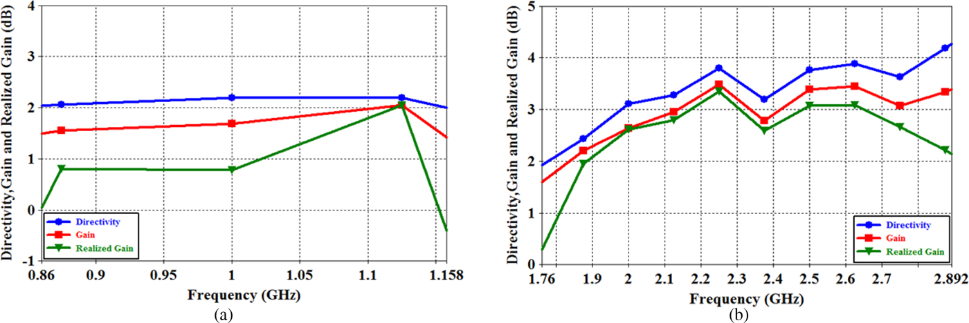
Fig. 11. Simulated directivity, gain, and realized gain of the proposed antenna versus frequency, (a) low-frequency band and (b) high-frequency band.
Radiation efficiency and total efficiency
Figure 12 illustrates the simulated radiation efficiency and total efficiency of the proposed antenna. For the lower band shown in Fig. 12(a), the radiation efficiency (total efficiency) varies from 87.92% (68.1%) to 96.58% (96.49%). Meanwhile, for the upper band shown in Fig. 12(b), the radiation efficiency (total efficiency) varies from 81.57% (61.5%) to 94.94% (90.04%). The radiation efficiency and the total efficiency are acceptable for practical mobile phone applications.

Fig. 12. Simulated radiation efficiency and total efficiency of the proposed antenna versus frequency, (a) low-frequency band and (b) high-frequency band.
Proposed antenna with packaging
The measured and simulated results depicted in Fig. 7 are without the presence of the plastic housing of the antenna system. Moreover, to simulate practical mobile phone casing, a plastic casing with a 1 mm thick plastic housing, a relative permittivity of 3.0, and a conductivity of 0.02 S/m, is used to enclose the system circuit board with a gap of 2 mm in distance between the plastic casing and the system circuit board. Notice that the height of the plastic housing is 12 mm, an attractive height for thin mobile phones, and the presented planar monopole antenna, is at the center of the plastic housing, as demonstrated in Fig. 13(a). Results of the simulated reflection coefficient against frequency about the two cases (with or without the presence of the plastic housing) for the proposed prototype antenna by using Ansoft HFSS and CST MWS are illustrated in Figs 13(b) and 13(c), respectively. As can be seen from Figs 13(b) and 13(c), the proposed antenna is capable of generating the lower and upper bands in both cases.

Fig. 13. (a) Proposed antenna with packaging, simulated reflection coefficient against frequency about the two cases (with or without the presence of the plastic housing) for the proposed antenna, (b) using Ansoft HFSS and (c) using CST Microwave Studio.
Comparison with published work
A comprehensive comparison between the proposed prototype antenna and the previous antenna based on the antenna size, the area it occupies, and its bandwidth is given in Table 2. It is clearly observed from the table below that the prototype antenna has a low profile and occupies the smallest size compared with the other published works. Furthermore, in terms of bandwidth, the proposed antenna can provide two wide operating bands to cover the desired frequency ranges of 848–1152 MHz and 1736–3000 MHz, including the GSM850/GSM900 and DCS1800/PCS1900/IMT2000/UMTS 2100/WLAN2400/ISM2450/LTE2300/LTE2500 operation.
Table 2. Performance comparison of the proposed antenna with other reported antennas.

Sar analysis of the proposed antenna
The SAR is a measure of power radiated and absorbed by the human body over the specific volume of the head tissue and calculated in terms of Watts/kilogram (W/kg) [Reference Husni, Islam, Faruque and Misran25]. The SAR is defined as:
 $$SAR = \displaystyle{{\sigma {\vert E \vert } ^2} \over {2\rho}}, $$
Where σ is the tissue conductivity (S/m), E the root mean square (rms) electric field (V/m), and ρ the tissue density (kg/m3).
For mobile phone compliance, the SAR value must not exceed the exposure guidelines [26, Reference Jammet, Bernhardt, Bosnjakovic, Czerski, Grandolfo, Harder, Knave, Marshall, Repacholi, Sliney, Stolwijk and Duchene27]. For example, the SAR limit specified in IEEE C95.1: 1999 is 1.6 W/kg in a 1-g averaging mass while that specified in ICNIRP guidelines is 2 W/kg in a 10-g averaging mass [Reference Fung, Leung and Chan28]. The regulation in SAR has been harmonized to 10-g with a limit of 2 W/kg specified in IEEE C95.1: 2005 with the major difference discussed in detail in [Reference Lin29].
The SAR values of the proposed antenna are analyzed using Ansoft HFSS and CST MWS. In this study, three human head models have been used. The first model is a homogeneous spherical head model with a diameter of 200 mm, composed of a glass shell with 5 mm thickness and dielectric constant εr = 4.6 and a sphere with 95 mm radius as the head equivalent materials [Reference Belrhiti, Riouch, Tribak, Terhzaz and Sanchez30, Reference Belrhiti, Riouch, Tribak, Terhzaz and Sanchez31]. Properties of the head tissue-equivalent dielectric and the glass shell are given in Table 3 [Reference Belrhiti, Riouch, Tribak, Terhzaz and Sanchez30–Reference Belrhiti, Riouch, Tribak, Terhzaz and Sanchez33]. The second model is a SAM phantom head model provided by CST MWS, consists of two layers namely shell and fluid. The third model is a HUGO human head model, also called HUGO. The HUGO head model consists of fifteen types of tissues, namely: Bones, Blood, Cartilages, Eye, Fat Tissue, Glands, Gray Substance, Lens, Marrow, Mucous Membrane, Neuronal Fabric, Nervus Opticus, Skin, Skeleton Muscle, White Substance. The dielectric properties of the HUGO voxel model are obtained from [34]. The HUGO head model is performed at the resolution of 1 mm.
Table 3. Properties of the tissue-equivalent dielectric used for the spherical head model.

The gap distances between the antenna and the human head model are 5, 10, and 20 mm. In the study, the mobile phone, with the proposed antenna is positioned at the bottom of the system circuit board. The input power for testing the SAR is 24 dBm or 0.25 W for 900 MHz and 21 dBm or 0.125 W for 1800, 1900, 2000, 2300, and 2450 MHz.
SAR distribution in homogenous spherical head model and in the SAM phantom head model
Figure 14 describes the effect of the gap distance between the proposed antenna and the homogenous spherical head model on the SAR levels using the software Ansoft HFSS. The variation levels of the local SAR and the SAR averaging over a mass of 1 and 10 g, at various gap distances 5, 10, and 20 mm between the presented prototype antenna and the homogenous spherical head, at different frequencies of 900, 1900, 2000, and 2300 MHz is plotted in Fig. 14. As can be seen from the obtained results, the levels of the local and the average SAR decreases when the gap distance increases. Also, when penetrating the homogenous head, the SAR levels for 900, 1900, 2000, and 2300 MHz decrease rapidly.

Fig. 14. Local SAR and average SAR variation in 1 and 10 g head tissues for the homogenous head model, at different frequencies, at various gap distances.
The simulated 3D 1 g SAR (W/Kg), at typical operating frequencies of 900, 1800, 1900, and 2000 MHz, and 10 g SAR (W/kg) distributions, at the 900, 1800, 2300, and 2450 MHz, within the SAM phantom head model are illustrated in Figs 15(a) and 15(b), respectively, and were, obtained by using CST MWS, the gap distance being fixed to 5 mm.

Fig. 15. Simulated 3D (a) 1 g SAR distributions (W/kg) ,at the frequencies of 900, 1800,1900, and 2000 MHz and (b) 10 g SAR distributions (W/kg) ,at the frequencies of 900, 1800, 2300, and 2450 MHz, inside the SAM phantom head model, with 5 mm gap distance using CST MWS.
The simulated calculated SAR values within the homogenous spherical head model and SAM phantom head, at the selected operating frequencies of 900, 1800, 1900, 2000, 2300, and 2450 MHz, for 1 and 10 g head tissues obtained using CST MWS are listed in Table 4. It is found that the SAR values for 1 and 10 g head tissues are decreased when the gap distance is increased from d = 5 to d = 20 mm. From this table, when the gap distance is fixed to 5 mm, it is noticed that the peak SAR values for 1 and 10 g head tissues are all below 1.31 and 0.766 W/Kg, respectively, for the homogenous head except 900 MHz, also the peak 1 and 10 g SARs are all below 1.49 and 1.03 W/Kg, respectively, for the SAM phantom head except 900 MHz. Also, from the obtained results the peak 1 g SAR values for d = 10 mm are 1.48, 0.94, 0.848, 0.775, 0.50, and 0.613 W/Kg, at 900, 1800, 1900, 2000, 2300, and 2450 MHz, respectively, for the SAM phantom head model. For all selected frequencies the SAR values in 1 g head tissue were always higher than SAR in 10 g head tissues. In addition, the obtained results show that the peak 1 and 10 g SARs, for the homogenous head model and SAM phantom head are close to each other. Moreover, the obtained SAR values are all below the SAR limit of 1.6 W/kg for the 1 g head tissue (according to FCC standard) except f = 900 MHz and 2.0 W/kg for the 10 g head tissue (according to ICNIRP standard).
Table 4. Simulated SAR values for 1 and 10 g, inside the homogenous spherical head model and the SAM phantom head, for the antenna placed at the bottom of the mobile phone; Three gap distances d = 5, d = 10, and d = 20 mm between the antenna and the human head model are investigated.

SAR distribution in the HUGO human head model
In this section, after the SAR validation using homogenous spherical head model and SAM phantom head, we investigate the SAR in the anatomically based head model, called HUGO human head model. The SAR distributions inside the HUGO voxel model are evaluated for two gap distances 5 and 10 mm, for the selected operating frequencies, for the proposed antenna placed at the bottom position of the mobile phone.
The 2D top cut plane view of 10 g SAR (W/kg) distributions, at the frequencies of 900, 1800, 1900, and 2000 MHz, and 1 g SAR (W/kg), at the selected operating frequencies of 900, 1900, 2300, and 2450 MHz, inside the HUGO human head model are depicted in Figs 16(a) and 16(b), respectively, and were obtained by using CST MWS, the gap distance being fixed to 5 mm.

Fig. 16. Simulated 2D (a) 10 g SAR distributions (W/kg), at the frequencies of 900, 1800, 1900, and 2000 MHz, and (b) 1 g SAR distributions (W/kg), at the frequencies of 900, 1900, 2300, and 2450 MHz, inside the HUGO human head model, with 5 mm gap distance using CST MWS.
Table 5 gives a summary of the simulated peak 10 and 1 g SARs, inside the HUGO human head, for the selected operating frequencies. From the obtained results, it is clearly observed that the averaged 10 and 1 g SARs results, are all well below the SAR limits of 2.0 and 1.6 W/kg standards respectively, at all frequencies, for the two gap distances. When the gap distance is fixed to 5 mm, the obtained maximum peak average SAR over 1 and 10 g are 1.57 and 1.07 W/kg, respectively, at 900 MHz, whereas the obtained minimum peak average SAR over 1 and 10 g are 0.308 and 0.178 W/kg, respectively, at 2300 MHz. Furthermore, from the obtained results listed in Table 4 and Table 5, we conclude that the proposed prototype antenna is very promising for practical mobile phone applications.
Table 5. Simulated SAR values for 1 and 10 g, inside the HUGO human head model, for the antenna placed at the bottom of the mobile phone; Two gap distances d = 5 and d = 10 mm between the antenna and the HUGO head model are investigated.

Conclusion
In this paper, a novel low-profile planar monopole internal antenna for GSM/ DCS/PCS/IMT2000/UMTS2100/WLAN2400/ISM2450/LTE operation in the mobile phones has been presented, fabricated, and studied. The antenna is formed by multi-branches, tapered feeding line and F-shaped slots in the ground plane and occupies a small size of only 18.5 × 46 mm2. The very good agreement is obtained between the simulated and experimental results. Hence, the proposed prototype planar antenna has two wide frequency bands which cover the lower frequency range of 848–1152 MHz for the GSM850/GSM900 and the higher frequency range of 1736–3000 MHz for the DCS1800/PCS1900/IMT2000/UMTS2100/WLAN2400/ISM2450/LTE2300 and LTE2500 bands. Good radiation characteristics and antenna peak gain for frequencies over the desired operating bands have been obtained. The SAR values of the proposed antenna placed at the bottom position of the mobile phone have also been investigated. Three human head models have been implemented, a homogenous spherical head, SAM phantom head, and HUGO human head model. The results demonstrate that the obtained SAR values meet the limit of 1.6 W/kg for the 1 g head tissue and 2.0 W/kg for the 10 g head tissue. Furthermore, the obtained results, including reflection coefficient, directivity, antenna gain, realized gain, efficiency, radiation patterns, and low SAR values, reveal that this simple and low-cost design is especially suitable for practical applications in the mobile phones as an internal antenna.
 Lakbir Belrhiti was born in Erfoud, Morocco, He received the Bachelor degree in Electronics from Faculty of Sciences and Techniques, University Moulay Ismaïl, Errachidia, Morocco in 2010. He received a Master degree in Telecommunications and Microwave Devices from National School of Applied Sciences, University Sidi Mohamed Ben Abdellah, Fez, Morocco in 2012. He is currently working toward the Ph.D. degree at National Institute of Posts and Telecommunications–INPT. His research and development interests include microstrip antenna, fractal antenna, ultra-wideband (UWB), miniature and multiband antennas, slot antenna, notched antenna, multiband and wideband mobile phone antennas, MIMO antennas for handheld devices, human exposure to EM fields, interaction between the human body and the mobile terminal's antennas and smart antennas, and the biological effects of electromagnetic fields.
 Fatima Riouch is a professor in the National Institute of Posts and Telecommunications - INPT, Rabat, Morocco. She received her engineering degree from ENAC–France in 1983. She then prepared a Certificate of Preparation for Research in Electronics and Telecommunications from Mohammadia School of Engineering – EMI, Rabat, Morocco. She has held several leadership positions at INPT where she participates in teaching, administration and research work. Her professional interests include the area of antennas and wave propagation in the mobile radio environment.
 Abdelwahed Tribak was born in Larache, Morocco, in 1981. He received the M.Sc. degree in physics from Abdelmalek Essaadi University, Tétouan, Morocco, in 2006. He received a Master degree in communications engineering from the University of Cantabria, Santander, Spain, in 2008, and received the Ph.D. of Telecommunication degree in 2011, from the University of Cantabria, Santander, Spain. Since 2006–2011, he has been with the Department of Communications Engineering, University of Cantabria. Since 2011 he is an Associate Professor in the National Institute of Posts and Telecommunications, Rabat, Morocco. His main area of activities is microwave circuits and systems; antenna feed subsystems for satellite and radio-astronomy applications.
 Jaouad Terhzaz was born in Kalaat Esrghna, Morocco, in September 1977. He received the Ph.D degree in Electronics and Telecommunications from Mohammadia School of Engineering –EMI, Mohammed V University-Agdal, Rabat, Morocco, in 2008. He is currently a professor of physics in CRMEF, Casablanca, Morocco. He is involved in dielectric characterization of materials using microwave techniques and antennas systems design for mobile communications.
 Angel Mediavilla Sanchez was born in Santander, Spain, in 1955. He graduated in 1978 and received the Doctor of Physics (Electronic) degree with honours in 1983, both from the University of Cantabria, Santander. From 1980 to 1983 he was Ingenieur Stagiere at THOMSON-CSF, France. He is currently head of the Communications Engineering Department at the University of Cantabria. He has a wide experience in the analysis and optimization of nonlinear microwave active devices. His research interests are nonlinear MESFET/HEMT and HBT device modeling with special application to the large signal computer design and new waveguide structures for antenna feed systems.


