1. Introduction
Ultra wide band (UWB) communication (3.1–10.6 GHz) [Reference Federal Communications Commission1] is considered as a promising technology for wireless communication systems because of large bandwidth (BW), reduced fading from multi-path, good transmission data-rate and low-power requirements. Antenna is one of the important components, which is responsible for the performance of the UWB communication systems. The recent trends of the development of UWB antennas focus on the development of compact UWB planar antennas because of their simple and low-cost manufacturing process and easily integrating capability with the system board of host devices and lightweight.
The coplanar waveguide (CPW) fed is one of the feeding techniques, which enhances impedance matching for large BW and hence the design of UWB antenna can be realized. In CPW feeding technique, there is no ground on the back side of the planar antenna, which disturbs the radiation at bore-sight, and hence CPW fed UWB antenna suffers from poor gain characteristics [Reference Allen, Dohler, Okon, Malik, Brown and Edwards2–Reference Singhal, Pandey and Singh5].
Recently, to enhance the gain of the planar antennas, many gain enhancement techniques such as laminated conductor layers [Reference Ghosh and Das6], parasitic radiation patch [Reference Zhao, Huang, Li, Zhang and Wen7], by placing a metallic plate as a reflector [Reference Lin, Chang, Chen and Lai8], using microwave lens [Reference Cheung, Li, Wu and Yuk9], using array [Reference Guan, Zhang, Qian, Li, Cao and Yuan10], Fabry--Parot cavity [Reference Costa and Monorchio11], Zero index material lens [Reference Meng, Lyu, Zhang, Wu and Li12], High impedance surface [Reference Amiri, Balanis and Birtcher13], Partially Reflecting Surface (PRS) [Reference Konstantinidis, Feresidis and Hall14,Reference Boutayeb, Denidni and Nedil15], etc. have been reported. In PRS types of structures, the dielectric layer fabricated with parasitic patches (PPs) is placed at approximately 1.5λ distance from the ground plane. This layer has characteristics of partial reflection, so it is known as PRS. These structures are fed by a dipole, microstrip antenna or waveguide. The gain of an antenna with PRS depends on reflection coefficient of PRS, PPs dimension, spacing between PPs, distance between PRS layer and radiating element, etc.
In this paper, an efficient, high gain and ultra wideBW antenna is presented. This paper gives the solution of poor gain characteristics of the CPW fed UWB antenna. With best of our knowledge, in this paper, first time gain enhancement using PRS in the design of CPW fed UWB antenna is reported.
This paper is organized in four sections. In the first section, a brief literature survey of the different gain enhancement techniques, the proposed technique and novelty of the proposed design is presented. In section “Antenna with PRS geometry and its design theory”, the description of the CPW fed UWB antenna with PRS geometry and its design theory included. Third section describes experimental results, which contains the comparative results of gain (with and without PRS), the current distribution of PRS and the radiation pattern of the antenna (with and without PRS). The last section covers the conclusion and future work.
2. Antenna with PRS geometry and its design theory
Figures 1(a) and 1(b) show a top view anda front view of the proposed antenna. The antenna is fed with the CPW technique. The antenna is parasitically coupled with square parasitic patch array (SPPA), which is fabricated from an FR4 superstrate. The complete design dimensions are shown in Table 1.
Fig. 1. Design geometry of UWB antenna: (a) top view (in the absence of PRS), (b) front view of the proposed antenna (d = 13 mm, s = 14 mm, h = 57.61 mm), (c) lateral view.
Table 1. Design dimensions of proposed CPW fed UWB antenna with PRS

The array of PPs is known as PRS and it is fabricated on the lower side of the superstrate layer. The superstrate layer is the FR4 substrate with permittivity of 4.4 and loss tangent of 0.018. The parasitic patch dimensions and spacing between them are optimized in order to enhance the gain of the antenna. The length and width of superstrate are 169 × 169 mm2 (4.4λ × 4.4λ at 7.78 GHz) and thickness is 1.524 mm. Each cell dimension (d × d) are 13 × 13~mm2 (0.33λ × 0.33λ at 7.81 GHz), and the spacing or lattice constants of the patches is 14 mm (0.37λ at 7.78 GHz) as shown in Fig. 2. In the proposed structure, the air is act as a dielectric medium between the main radiating element of the antenna and PRS to achieve high efficiency and wide BW. The patch antenna is fed through an SMA jack PCB edge mount RF connector of 50~Ω. The antenna is designed to operate over 3.8–8.8 GHz of UWB. The superstrate layer is positioned at a height of 1.5λ 0 above the ground plane, where λ 0 is the free-space wavelength corresponding to a central frequency of 7.78 GHz.
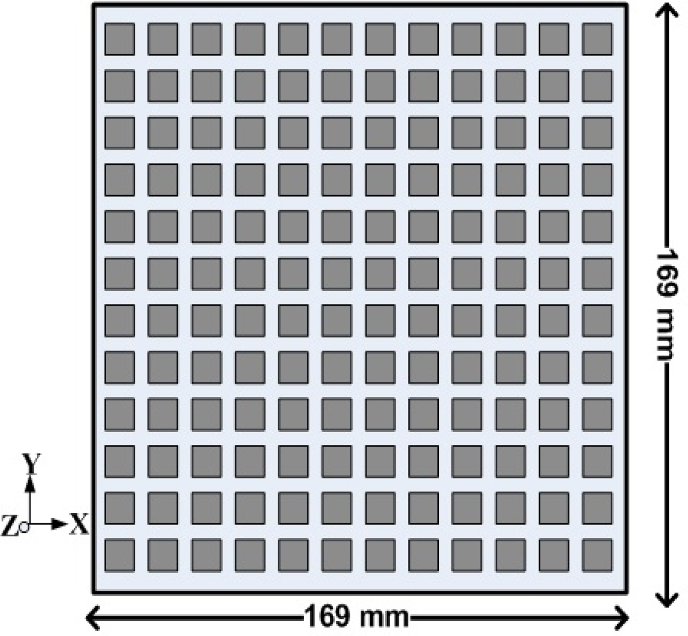
Fig. 2. Design of the proposed PRS.
General characteristics of the cavity are, it resonates only at a specific frequency, which results a narrowband resonant antenna. For getting a wideband resonant antenna that maintains the resonance condition over the wide operating frequency band, the reflection phase of the PRS should increase with frequency, as described in [Reference Ge, Esselle and Bird16]. Moreover, every cavity has numerous resonant frequencies that correspond to electromagnetic field modes satisfying necessary boundary conditions on the walls of the cavity. Because of these boundary conditions that must be satisfied with resonance (tangential electric fields must be zero at cavity walls), it follows that cavity length must be an integer multiple of half-wavelength at resonance [Reference Pozar17]. In the proposed structure, the CPW fed radiating element and PRS behaves as a cavity and it provides wideband impedance matching (VSWR≤ 2) over the entire ultra wide BW.
In our proposed design, for getting increment in overall reflection phase of the PRS with increment of frequency, the dimensions of the copper cell (d × d), spacing between the adjacent cell, distance between PRS and radiating elements, etc. optimized using CST Microwave Studio simulator V. 2017 [18]. The enhancement of the gain can be explained by partial reflective theory [Reference Feresidis and Vardaxoglou19–Reference Trentini22].
Let the radiation pattern of a UWB source antenna be
 $$ E_{0}\cdot f (\alpha) $$
and for a plane wave, the PRS reflection coefficient (Γ), given by
 $$ \Gamma =\rho\cdot {\rm exp}(\,j\phi). $$
 The magnitude ρ and phase ϕ are generally function of the frequency, the angle of incidence, and the polarization of the emerging electromagnetic wave. An electromagnetic wave radiated by a UWB antenna is not exactly a plane wave when it reaches the PRS. This variation has been neglected in this analysis. To make mathematical analysis simple, PRS is assumed to be lossless here. As shown in Fig. 1 (c), at the phase font, the phase of the referent wave (0th wave) has the relative amplitude of  $\surd (1-\rho ^{2})$ due to the transmission through the PRS and the successive (1st) wave has the lower relative amplitude of
  $ \rho \cdot \surd (1-\rho ^{2})$ due to the one extra reflection from the PRS. This first successive wave is also shifted in phase with respect to the referent wave, due to the reflections from the PRS and ground. The phase shift (δ) given by [Reference Tomislav20,Reference Khosronejad and Gentili21]:
 $$\delta = - \displaystyle{{4\pi d} \over \lambda } \cdot \cos (\alpha ) - \pi + \phi $$
where λ is the free-space wavelength. The first part of equation (3) refers to the difference between the path lengths, − π is due to the reflection from the ground plane. For the rest of the successive waves (second, third, etc.) the same theory can be applied, so the relative amplitude and phase of the nth wave in general can be given by
 $$ \rho^{n}\cdot \surd (1-\rho^{2}), $$
 $$\delta _n = \delta \cdot n = n \cdot ( - \displaystyle{{4\pi d} \over \lambda } \cdot \cos (\alpha ) - \pi + \phi ),$$
respectively. To achieve the radiation pattern of the PRS antenna, all the waves must be added, and the sum must be modulated by the radiation pattern of the source antenna. It is given by [Reference Tomislav20,Reference Khosronejad and Gentili21]
 $$E(\alpha ) = E_0 \cdot F(\alpha ) \cdot \sum\limits_{n = 0}^\infty {\rho ^n} \cdot \surd (1 - \rho ^2) \cdot {\rm exp}(\,jn\delta ).$$
 The part  $\sum\nolimits_{n = 0}^\infty {\rho ^n} \cdot \surd (1 - \rho ^2) \cdot {\rm exp}(jn\delta )$ forms a geometric series. As the PRS is a passive device, the reflection coefficient (Γ) will be <1, and equation (6) can be written as
 $$E(\alpha ) = E_0 \cdot F(\alpha ) \cdot \displaystyle{{\surd (1 - \rho ^2)} \over {1 - \rho \cdot {\rm exp}(\,j\delta )}}.$$
The power pattern given by the standard equation
 $$S(\alpha ) = \displaystyle{{\vert E(\alpha )\vert {^2}} \over {2\eta }}$$
combining equations (7) and (8), the resultant power pattern of the lossless PRS antenna can be obtained, and it is given by
 $$\eqalign{S(\alpha ) =& \displaystyle{{\vert E_0 \cdot F(\alpha )\vert {^2}} \over {2\eta }} \cr & \cdot \displaystyle{{1 - \rho ^2} \over {1 + \rho ^2 - 2\rho \cdot \cos (\phi - \pi - \displaystyle{{4\pi d} \over \lambda } \cdot \cos (\alpha ))}}}$$
where η is the intrinsic impedance of free space (120π). The first part of equation (9) is the power pattern of the antenna and the second part gives the value of extra directivityD e. In other words, the resultant power pattern of the PRS antenna is the power pattern of the source antenna multiplied by the extra directivity.
Maximum power obtained at boresight (α = 0) is when the phase condition
 $$\phi - \pi - \displaystyle{{4\pi d} \over \lambda } = 2N\pi ,$$
where N = 0, 1, 2, 3, …
At boresight, the extra directivity in the broadside direction reaches its maximum value [Reference Feresidis and Vardaxoglou19–Reference Khosronejad and Gentili21]:
 $$D_e = \displaystyle{{1 + \rho } \over {1 - \rho }}$$
and thus high gain can be achieved.
The half-power fractional BW, calculated for a highly reflecting surface with frequency independent reflection characteristics, is [Reference Feresidis and Vardaxoglou19]
 $$BW = \displaystyle{{\Delta f} \over {\,f_0}} = \displaystyle{\lambda \over {2\pi L_r}}\displaystyle{{1 - \rho } \over {\surd \rho }}$$
for getting maximum gain within a certain frequency range the phase of the reflection coefficient of the PRS must satisfy the following relationship: [Reference Feresidis and Vardaxoglou19]
 $$\phi = \displaystyle{{4\pi L_r} \over c}f - (2N - 1)\pi .$$
In our proposed design, the distance L r optimized such thatequation (13) satisfies and hence realization of the higher gain occurs. Moreover, achievement of high gain can be also explained based on the increase in the total effective aperture area of the antenna. It is observed that, due to PRS, focusing effect becomes dominant. The phase distributions of the radiated fields with a PRS layer is observed to be more uniform than one without the PRS layer, which plays a major role in an increase in effective aperture area and gain. The focusing effect and phase smoothness increases directivity of the antenna and hence gain of the antenna increases. In addition, according to equation (11), the gain of the antenna increases as increment in reflection coefficient [Reference Vaidya, Gupta, Mishra and Mukherjee24].
3. Experimental results and discussion
To validate the proposed design, two laboratory prototypes: one without PRS and other one with PRS; were fabricated. The photograph of the both fabricated antennas is shown in Fig. 3. The return loss (S 11) of both antennas was measured using 67 GHz Keysight Technologies make (Model no. N5227A PNA) Vector Network Analyzer of Indian Institute of Technology, Roorkee, India; as shown in Fig. 4(a).

Fig. 3. Fabricated UWB antenna. (a) Top view, (b) antenna with PRS.

Fig. 4. Measurement setup of proposed antenna (with PRS). (a) Antenna with VNA for BW measurement, (b) antenna at anechoic chamber for measurement of radiation pattern.
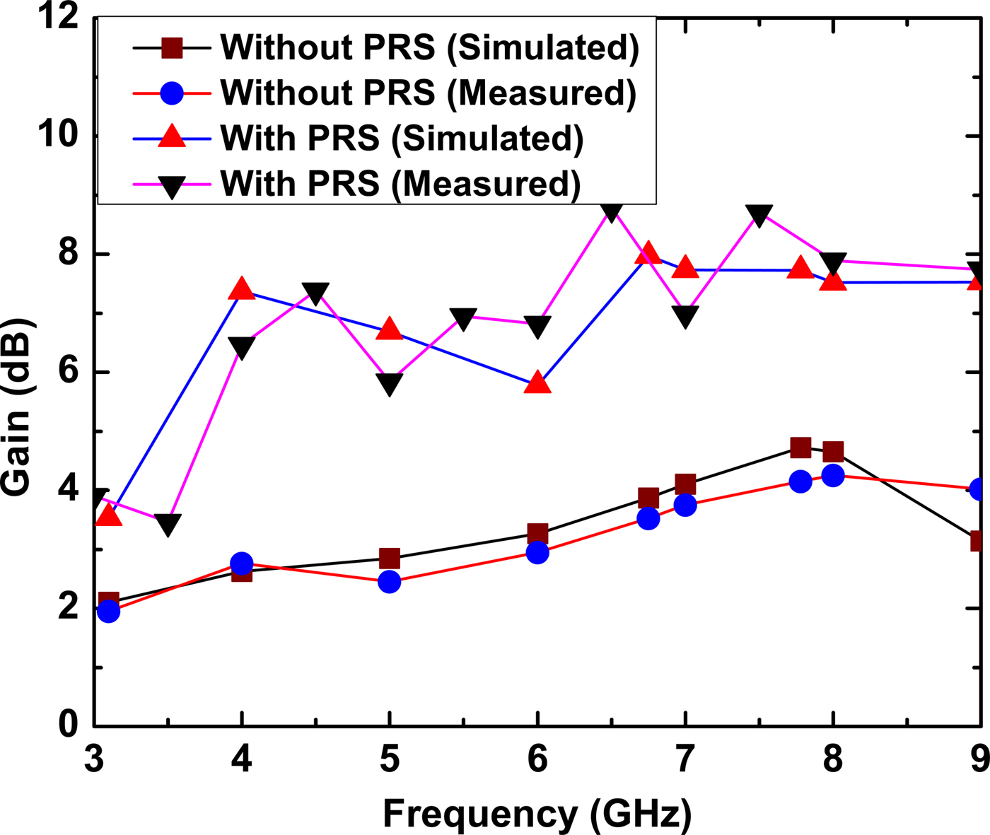
The simulated and measured S 11 of the PRS antenna are given in Fig. 5. In simulation, 3–8.5 GHz BW (S 11 ≤ −10 dB) obtained, while in measurement, BW of 3.8–8.8 GHz achieved. The slight mismatch between simulation and measurement of upper and lower cut-off frequencies of BW due to possible tolerance in dielectric constant in substrates, fabrication errors, etc. Here, as per standard definition of useful BW [Reference Balanis25], frequency between 3–8.5 GHz considered as useful radiated frequency, eventhough mismatch of the shape of the S 11. The simulated frequency response of the antenna gain, which demonstrates the effect of the PRS layer on the gain of the antenna is shown in Fig. 6. It is seen that, when PRS is employed, in the entire frequency band (3–8.5 GHz), average gain increased by 3--4 dB. When CPW fed UWB patch antenna feds SPPA, at boresight high radiation obtained. This is possible only if all PPs are fed in almost same phase and current induces at patches are in the same phase. In our design, all square PPs are embedded at different position of the dielectric layer and have different distance from the radiating element; therefore fed to each square parasitic patch involves different amplitude tapering and phase delay. Because of amplitude tapering, the gain decrease with different frequency. The amplitude tapering increases significantly with the increment in the distance from the radiating element. Thus, the gain of the antenna using PRS depends on PPs dimensions, spacing between two adjacent PPs, resonance distance, etc. [Reference Vaidya, Gupta, Mishra and Mukherjee23,Reference Vaidya, Gupta, Mishra and Mukherjee24]. The phase delay and amplitude tapering are not so significant between 3 and 4 GHz, hence constant increments in gain obtained between this frequency range, while the same become dominant between 4 and 6 GHz, so gain decrease between this frequency range. Figure 7 shows a gain comparison of simulated and measured results for antenna with and without PRS.
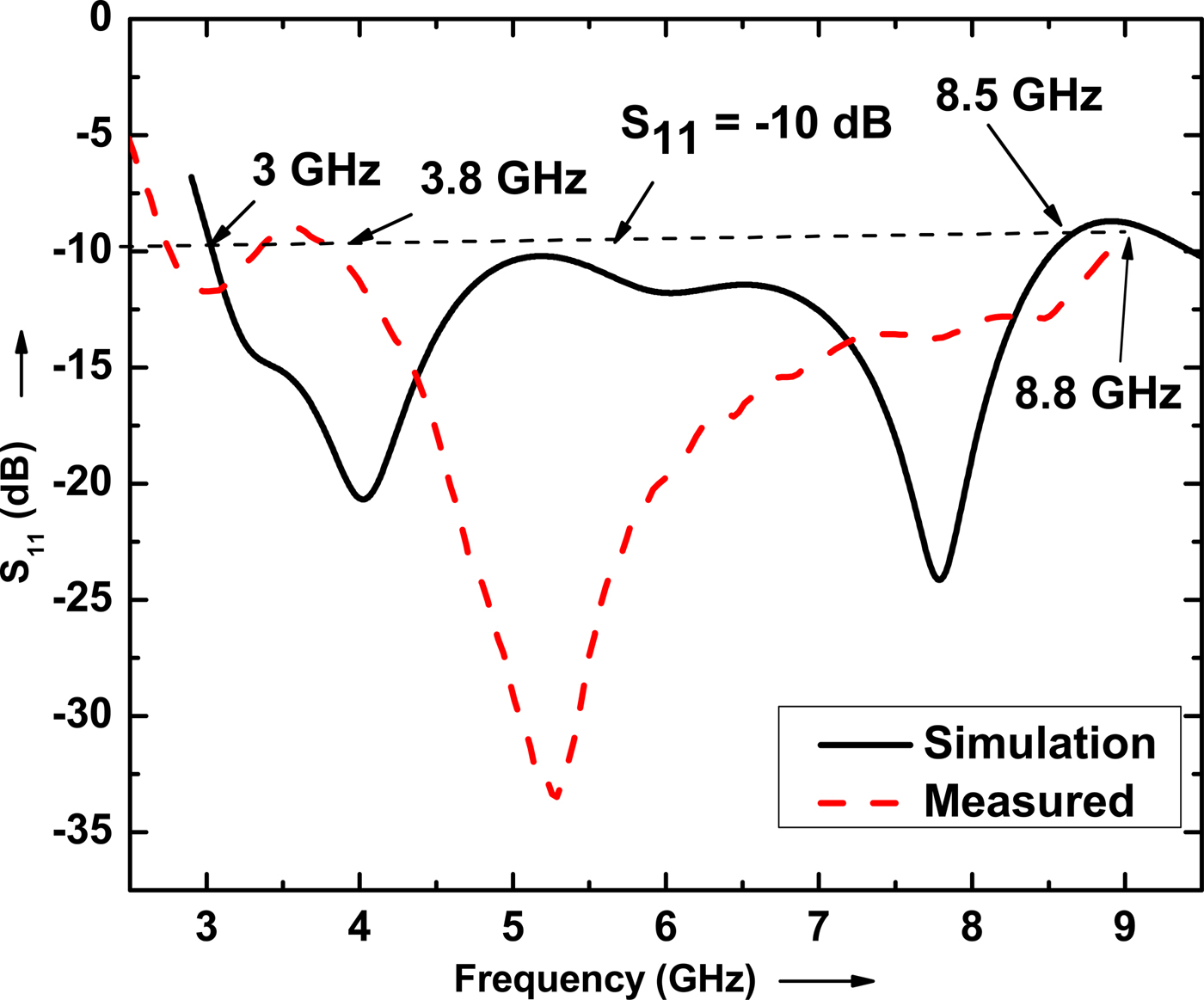
Fig. 5. Comparison of simulated and measured S 11 of antenna with PRS.
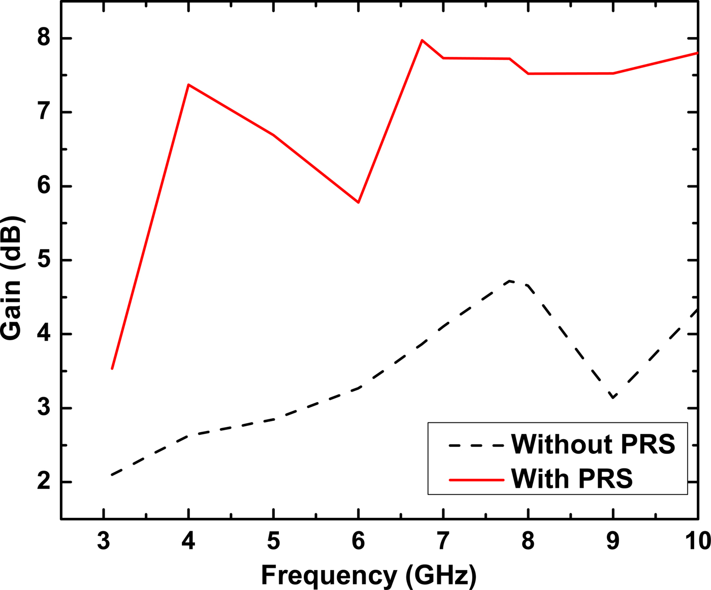
Fig. 6. Simulated gain comparison of antenna (with and without PRS).

Fig. 7. Simulated and measured gain comparison of antenna (with and without PRS).
Figure 8 shows the vector current distribution of PRS at 7.78 GHz. The current induced at each square parasitic element is almost in phase and decreases as the distance from the radiating element increases. From the current distribution at PPs, it can be concluded that CPW fed radiating element as well as all PPs contribute to the radiating field. The simulated electric field magnitude distribution for the antenna with and without the PRS, are given in Fig. 11. From this figure, it can be concluded that the electric field distribution of the aperture in case of PRS is more uniform and with higher magnitude as compared with without PRS configuration. Moreover, the effective aperture is also extended by adding the PRS, which leads to achievement of higher gain.
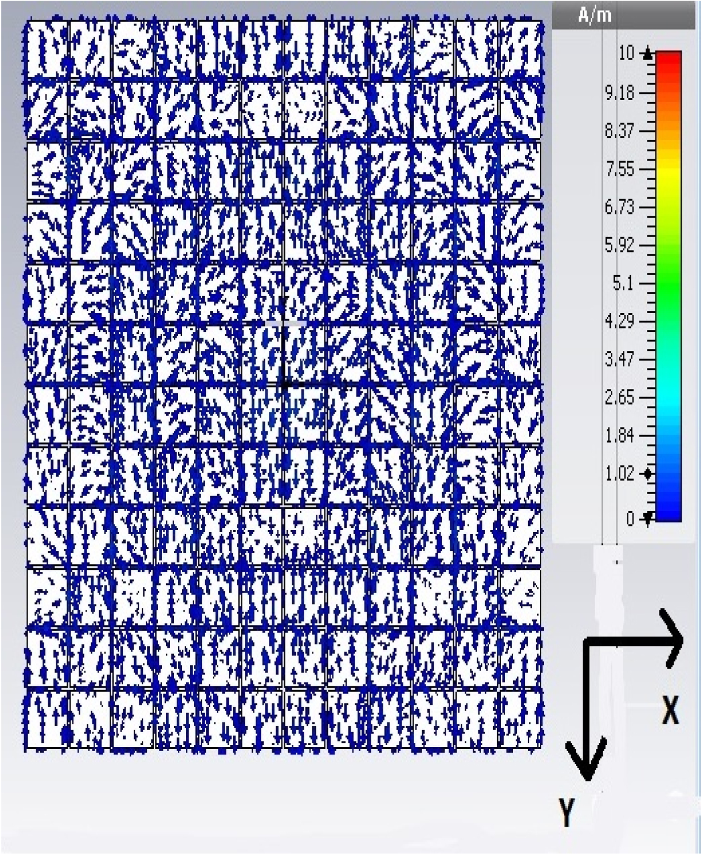
Fig. 8. Simulated current distribution of PRS at 7.78 GHz.
An anechoic chamber was used for measurement of the radiation properties of both the fabricated antennas as shown in Fig. 4(b). The simulated and measured E and H planes radiation pattern at 7.78 GHz for both configurations (with and without PRS) are shown in Fig. 9. UWB antenna without PRS structure, the main lobe is directed at 175° with 4.81 dB gain with broad half power beam width of 69.8°. Moreover, the side lobe level is − 0.5 dB obtained from simulation results, which is very high. The PRS makes the antenna beam highly directive and hence after the introduction of PRS, the main lobe is directed at 150° with 8.53 dB gain with very narrow half-power beam width of 15.3°, which is 219% less than without PRS structure. The side lobe level is − 1.5 dB obtained, which is 1 dB less than traditional antenna. Eventhough the main lobe direction will be change at different frequency, but the absolute gain of PRS antenna is higher than without PRS structure. So, it does not affect the application of the antenna. There is no any effect of PRS on the polarization of the antenna. There is good agreement between simulated and measured results.
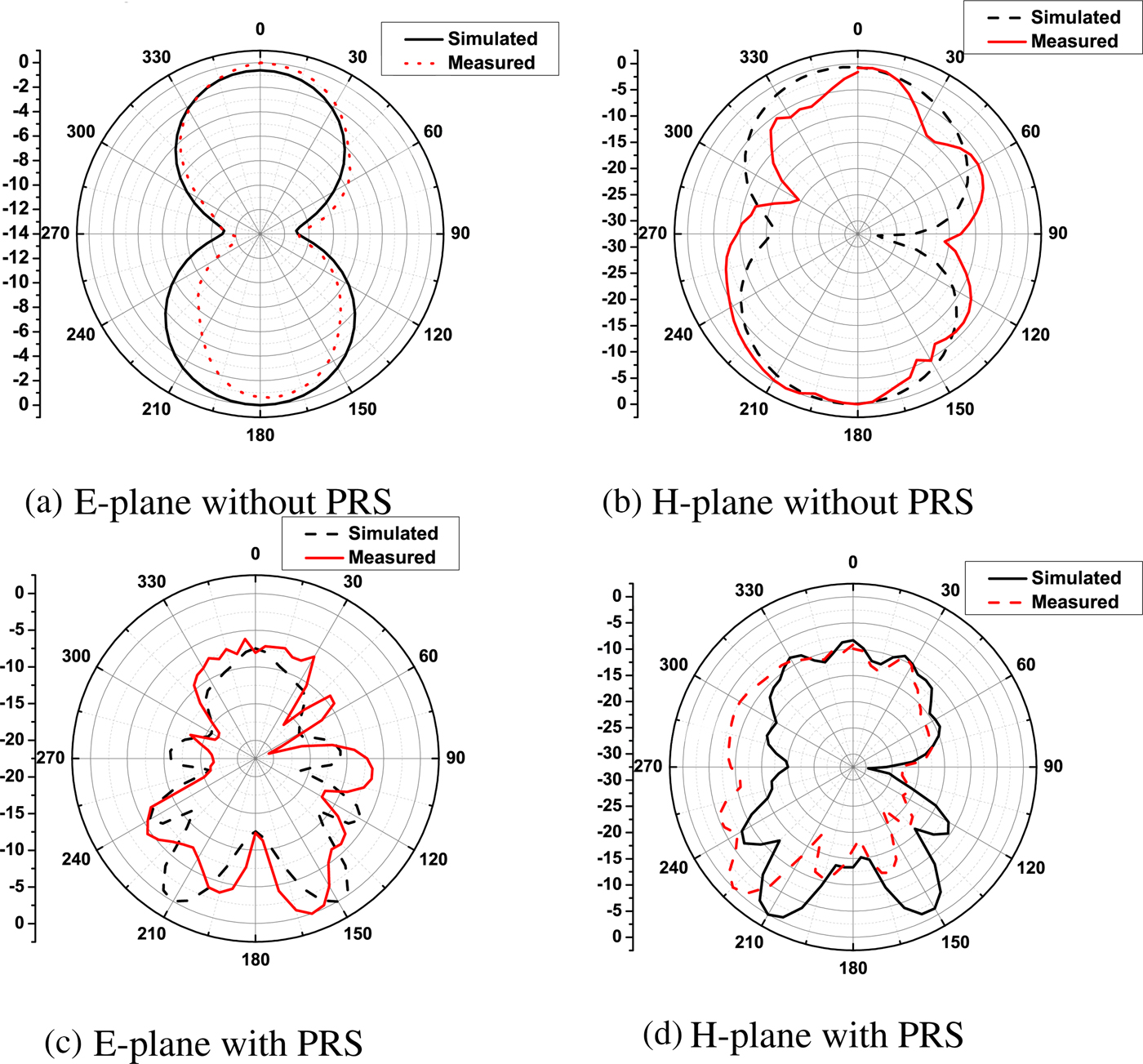
Fig. 9. Simulated and measured radiation patterns of the antenna (with and without PRS). (a) E-plane without PRS, (b) H-plane without PRS, (c) E-plane with PRS, (d) H-plane with PRS
Due to PRS, the directivity of the antenna increases and back radiation decreases. Figure 10 shows that antenna with PRS gives 3 to 12 time increment of front to back ratio (FBR) as compared to the antenna without PRS.
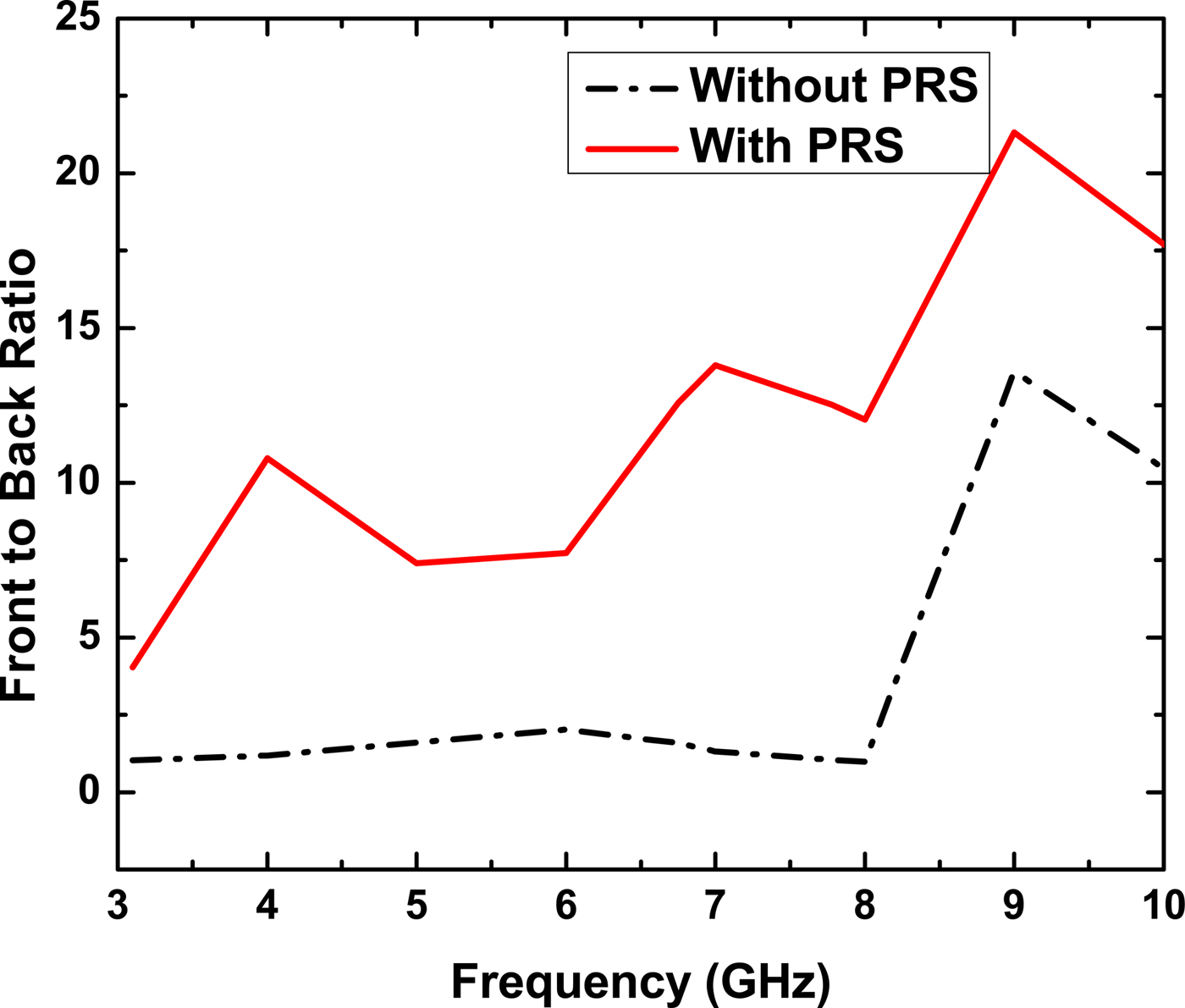
Fig. 10. Comparison of front-to-back ratio of radiation (with and without PRS).
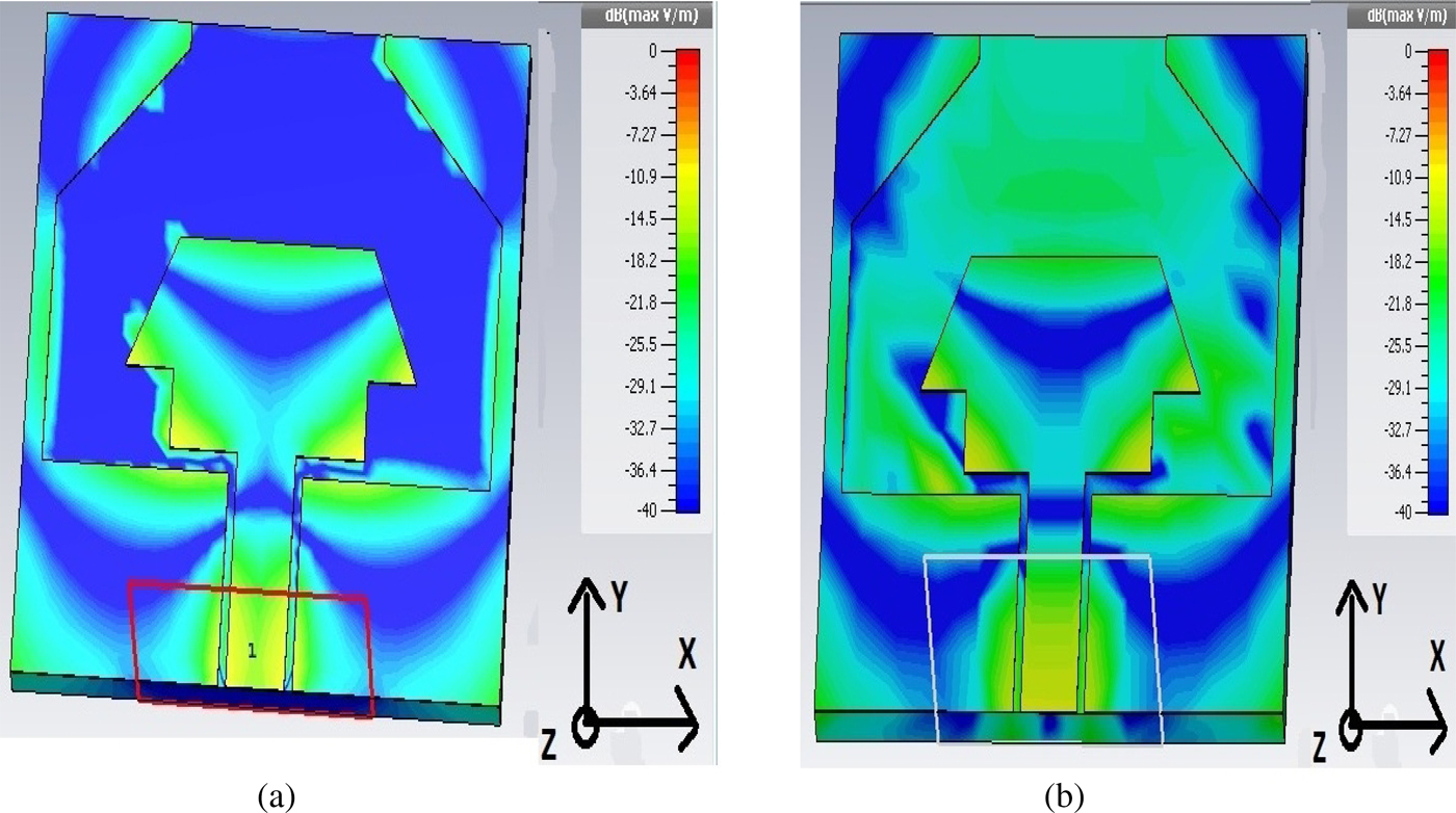
Fig. 11. Electric field magnitude distribution at 7.78 GHz frequency of the antenna: (a) without PRS, (b) with PRS, unit of color bar:dB (Max V/m).
Table 2 gives comparison of different gain enhancement techniques and proposed antenna with PRS technique. From open literature, we considered the maximum BW and maximum gain obtained using different gain enhancement techniques. Our proposed antenna gives a BW of 3.8--8.8 GHz with a distributed gain of 3.8--8 dB. In the comparative Table 2, for our proposed design, average gain of 6 dB considered. Our proposed antenna gives a maximum gain BW of product of 30 dB--GHz, which is better as compared with reported papers given Table 2.
Table 2. Comparison between earlier reported antennas with different gain enhancement techniques and proposed antenna with PRS technique

4. Conclusion
A CPW fed UWB antenna, employed with PRS has been designed and the application of the PRS for the gain enhancement of UWB antenna presented. By properly selecting the resonance distance, the shape of PPs, the space between PPs and optimize their dimensions enhancement of the gain about 3--4 dB obtained in UWB range. The proposed antenna gives rid of poor gain problem in UWB antenna with the cost of increment of size of antenna vertically. By employing uniform incremental/decremental gap spacing between PPs, the phase characteristics of the PRS can be controlled and thus further higher gain can be achieved. This may be the future scope of this work.
Acknowledgments
The author would like to thank the Gujarat Council on Science and Technology, Gandhinagar, Gujarat, India for funding under minor research project program. The authors gratefully acknowledge the department of Indian Institute of Technology, Roorkee, India for providing measurement facility. Authors are also thankful to Charutar Vidyamandal and the management of A D Patel Institute of Technology, Gujarat, India for their inspiration and support.
 Dr. Pravin R. Prajapati received the B.E. degree from the Government Engineering College, Modasa, Gujarat (1997), and the M.Tech. (Communication Systems) from Indian Institute of Technology, Banaras Hindu University, Varanasi, India (2006). He received his Ph.D. from Indian Institute of Technology, Roorkee, India (2015). Currently, He is working as an Associate Professor of the Department of Electronics and Communication Engineering at A. D. Patel Institute of Technology, Karamsad, Gujarat, India. He is the author/co-author of more than 44 research papers published in the refereed international/national journals and conferences. His research interests include Optical Fiber Communication, RF and Microwave Engineering, Microstrip Antennas, Optical Devices, Power Electronics and Communication Systems. Dr. Prajapati is a member of IEEE Antenna & Wave Propagation Society and life member of ISTE.
 Shailesh Khant received his B.E. in Electronics from S. P. University (1997) and Master in Engineering from the same University (2010). Currently he is pursuing his Ph.D. from Charotar University, Changa, Gujarat, India. Currently, He is working as an Assistant Professor at the Department of Electronics and Communication Engineering of A D Patel Institute of Technology, Gujarat, India. His main areas of interest include design of planar antennas, design of advanced Optical Fiber Communication systems, and Microwave Engineering. He is a life member of the ISTE.