Introduction
In recent years, the rapid development of the wireless local area networks (WLAN) has opened a new age, where the demand for high data rates and high reliability is extremely urgent. Multiple input multiple output (MIMO) communication technology has received much attention from researchers in the world thanks to its advantages, for example high data rate, high reliability, and high spectral efficiency. MIMO technology has been considered the best solution for most of the problems in wireless communication [Reference Paulraj, Gore, Nabar and Bölcskei1]. However, due to space limitation, the separation between antenna elements in MIMO systems is often small, leading to considerably large mutual coupling between them. Mutual coupling between elements in the array not only affects the antenna efficiency but also influences the correlation [Reference Zheng and Tse2]. The phenomenon of mutual coupling is considered as a bottleneck in the MIMO systems, and therefore, it is an urgent issue that needs to be solved. The easiest way to cancel mutual coupling is to increase the physical distance between elements. However, this leads to an increase in their occupied space. Therefore, this is not an optimized method. Currently, one of the most used solutions to improve mutual coupling for antenna is utilizing metamaterial structure thanks to its unique electromagnetic characteristics [Reference Wang, Duan, Li, Wang and Gong3].
From other aspects, microstrip patch antennas are the best choice in many existing and future wireless communication systems [Reference García-aguilar, Inclán-alonso, Vigil-herrero, Fernández-gonzález and Sierra-perez4–Reference Sourav Nandi6] because of its advantages such as small size, lightweight, easy fabrication, and low cost. However, they mainly suffer from performance limitations, for example narrow bandwidth, low gain, and low efficiency. Therefore, the improvement of the parameters for antenna is necessary. Different solutions have been adopted to improve the antenna parameters, for instance, gain enhancement including reflective surface [Reference Vaidya, Gupta and Mishra7], metamaterial [Reference Ahdi Rezaeieh, Antoniades and Abbosh8]; bandwidth enhancement consisting multiple substrate [Reference Gupta and Srivastava9], defected ground structure (DGS) [Reference Guha and Kumar10], and so on. Each method is based on its own principle. While the method of reflective surface enhances gain based on reflection principle to reduce side lobe and back lobe, utilizing metamaterial improves gain by current re-distribution. Similarly, an increase of thickness of substrate and creation of consecutive cavity resonators are rules to enhance bandwidth for antenna by using multiple substrate and DGS, respectively. Many works have been conducted to improve parameters for antenna such as: using meander line resonators [Reference Gulam Nabi Alsath, Kanagasabai and Balasubramanian11], electromagnetic band gap [Reference Exposito-dominguez, Fernandez-gonzalez, Padilla and Sierra-castaner12], metamaterial [Reference Dadgarpour, Sorkherizi and Kishk13], DGS [Reference Soltani, Lotfi and Murch14]. However, the mutual coupling in these papers is still large. For example, the isolation between elements in an array is only 16 dB in [Reference Gulam Nabi Alsath, Kanagasabai and Balasubramanian11]. Similarly, although the gain of the antenna is quite high, the isolation is not good (−15 dB) [Reference Exposito-dominguez, Fernandez-gonzalez, Padilla and Sierra-castaner12]. This issue also appears in papers of [Reference Dadgarpour, Sorkherizi and Kishk13, Reference Soltani, Lotfi and Murch14]. With these isolations, antennas cannot operate well. Moreover, in other documents [Reference Xu, Wang and Qi15, Reference Hwangbo, Yang and Yoon16], the parameters including gain and bandwidth of antennas are not enough to satisfy for applications. This shows that the simultaneous improvement of antenna parameters is not easy.
For this reason, this paper proposes a new metamaterial structure with a simple configuration, compact size, and planar in order to improve parameters for the antenna. The proposed structure is applied for a MIMO antenna including two sets of four elements (2 × 2). It is observed that the antenna operates at 5.8 GHz with the bandwidth of 1.78 GHz. In addition, the MIMO antenna is constructed with close separation of 2 mm from edge to edge thanks to a novel metamaterial structure, the mutual coupling between elements are under −18 dB. Besides, the antenna provides a high gain (9.2 dBi). The antenna has been characterized numerically using the CST Studio Suite and verified by measurements.
The proposed antenna array
The proposed metamaterial structure
Firstly, the model of the proposed metamaterial structure and its equivalent circuit are shown in Fig. 1. This idea is started from the structure of OE2 in [Reference Chen, O'Hara, Taylor, Averitt, Highstrete, Lee and Padilla17] and [Reference Withawat Withayachumnankul and Fumeaux18]. By the development in the shape of structure, the paper obtained a new configuration as shown in Fig. 1. Besides, to increase the value of L and C, this paper utilizes folded microstrip lines and this leads to reduce the frequency for the antenna. This is also one of the methods to minimize the size for the antenna. The radius of the proposed structure is 8.5 mm while the size of the substrate is 18 × 20 × 3.048 mm3.

Fig. 1. The model of the metamaterial structure: (a) the proposed structure, (b) the compensation structure.
Here, the equivalent circuits are generated based on the rule: the gaps between two microstrip lines make equivalent capacitance C while the inductances are introduced by microstrip lines. The proposed structure is planar. It is, therefore, easy for fabrication and design. Using both the compensation structure and the proposed structure help to make various about capacitances (C) and inductances (L). This leads to an ease in optimization to reach the better parameters for the antenna.
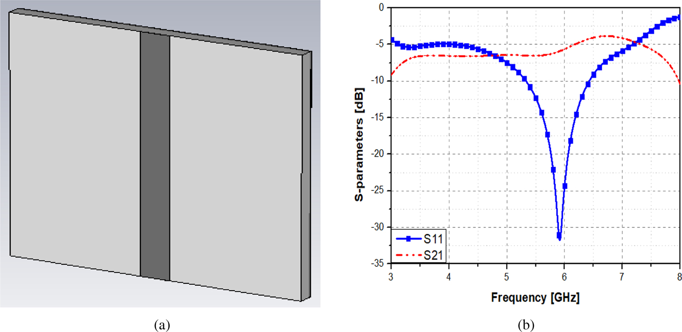
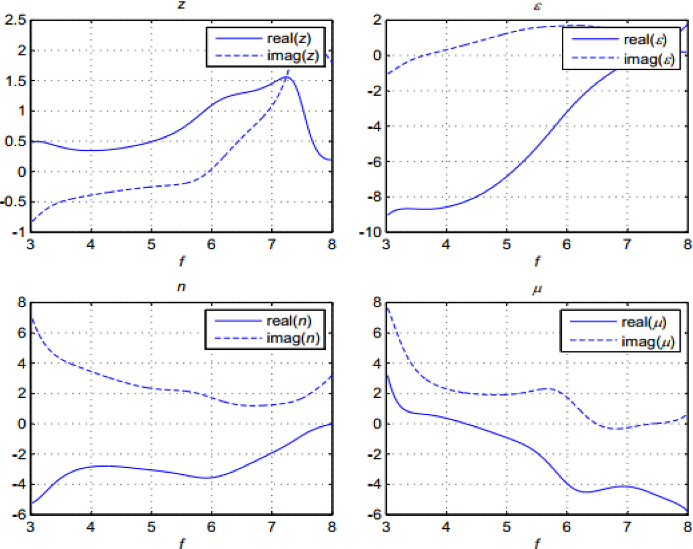
In order to confirm the proposed structure is metamaterial, the paper sets up a simulation including a microstrip transmission line of 50 Ω and the proposed structure on ground based on a substrate of Roger4350B with a thickness of 1.524 mm, ε r = 3.66, and tan δ = 0.0037. The proposed structure is designed for WLAN application at the central frequency of 5.8 GHz. By utilizing for the formulas in [Reference Chen, Grzegorczyk, Wu, Pacheco and Kong19], we can calculate the dielectric constant and the permeability from S-parameters. The model of the simulation and its S-parameters are shown in Fig. 2 while the simulation results (the impedance (z), the refractive index (n), the dielectric constant (ε), and the permeability (μ)) are illustrated in Fig. 3.

Fig. 2. The model for simulation set-up of the proposed structure.

Fig. 3. The results of the simulation set-up.
From Fig. 3, we can see that μ and ε are simultaneously negative in a frequency range from 4.5 to 7 GHz. This shows that the proposed structure is metamaterial and it supports a frequency range of 5.8 GHz.
Design of array antenna
The structure and model of the proposed antenna are shown in Fig. 4. Initially, a single array is realized for operating at a frequency band of 5.8 GHz. The antenna consists of an array antenna on top in the first substrate, second substrate, and ground layer with metamaterial structure on the bottom. The selected dielectric material is Roger4350B with parameters: h = 1.524 mm, ε r = 3.66, and tan δ = 0.0037. To increase gain for antenna, this paper uses two patches and they are placed next to each other with the closest distance between them is 0.5 mm. The array includes four elements and three T-junction power dividers. In this case, the power divider is considered as a three-port network with one input and two outputs. Moreover, these are equal dividers, and therefore, the powers at port 2 and 3 are half the one of port 1. This means that the parameters of S21and S31 are −3 dB. In addition, to match impedance for power dividers, transformers of λ/4 are used. Then, the impedances of transformers and transmission lines are given:
 $$Z = \sqrt {Z_0\cdot Z_{in}}, $$
 $$Z_0 = \displaystyle{{120\pi} \over {\sqrt {\varepsilon _r}}} \cdot \displaystyle{1 \over {\left( {\displaystyle{{w_f} \over h} + 1.393 + 0.677{\rm ln}\left( {\displaystyle{{w_f} \over h} + 1.444} \right)} \right)}}.$$
Fig. 4. The model of the proposed array: (a) the structure of the proposed array, (b) front view, (c) back view (dark color for metal and light color for substrate).
Figure 5 illustrates the model and S-parameters of the power divider. In Fig. 5, we can see that the power divider has large bandwidth (from 4 to 7.5 GHz) and low return-loss (−47.5 dB). In addition, the values of S21 and S31 are −3.2 dB.
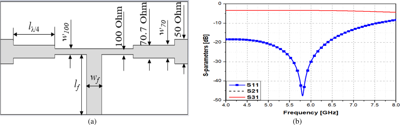
Fig. 5. The model and the parameters of the power divider.
Here, the distance between elements is approximately 27 mm. The dimension of an element is 8 × 11 mm2, while the overall size of the array is 70 × 72 × 3.048 mm3. Table 1 shows the parameters of the proposed array antenna while Table 2 illustrates the parameters of the power divider.
Table 1. Some parameters of the proposed antenna

Table 2. Some parameters of the power divider

To enhance gain for antenna, the paper uses metamaterial structure on the ground plane. The equivalent circuit of each cell is indicated in Fig. 1. Here, the capacitor and inductor are given by [Reference Rosu20]:
 $$C_i = \varepsilon _r\varepsilon _0 \times \lpar {A/h} \rpar ,$$
 $$L\lpar {nH/mm} \rpar = 0.2\left[ {{\rm ln}\left( {\displaystyle{l \over {w + t}}} \right) + 1.193 + 0.2235\displaystyle{{w + t} \over l}} \right],$$
in which, ε r and ε 0 are the permittivity of substrate and space, respectively, A is an area of plate (L × W), h is the height of substrate, w and l are the width and length of the ribbon, respectively, and t is the meta thickness.
If the elements are parallel, then the total capacitor and inductor can be calculated as follows:
 $$C_{total} = \mathop \sum \limits_{i = 1}^n C_i,$$
 $$\displaystyle{1 \over {L_{total}}} = \displaystyle{1 \over {L_1}} + \displaystyle{1 \over {L_2}} + \cdots \displaystyle{1 \over {L_n}},$$
while the elements are series:
 $$\displaystyle{1 \over {C_{total}}} = \displaystyle{1 \over {C_1}} + \displaystyle{1 \over {C_2}} + \cdots \displaystyle{1 \over {C_n}},$$
 $$L_{total} = \mathop \sum \limits_{i = 1}^n L_i.$$
Finally, the resonant frequency is given by
 $$f_{re} = \displaystyle{1 \over {2\pi f\sqrt {L_{total}C_{total}}}}. $$
Based on the above formulas, the final dimensions of the metamaterial structure as shown in Table 1 are optimized by CST Studio software. Moreover, the two branches of patches are also used to improve gain for antenna.
Besides, an indispensable component in the array antenna is power dividers. To match impedance for them, the quarter-wave transformers are used, then, the width of the transmission line is given by the expression:
 $$Z_0 = \displaystyle{{60} \over {\sqrt {\varepsilon _r}}} \cdot \ln \left( {\displaystyle{{8h} \over {w_f}} + \displaystyle{{w_f} \over {4h}}} \right)ifw/h \lt 1,$$
or using expression (2) if w/h > 1.
Design of MIMO array antenna
The model of the MIMO array antenna is illustrated in Fig. 6. Using Roger4350B substrate with a height of 1.524 mm, ε r = 3.66, and δ = 0.0037, the MIMO antenna gets a patch dimension of 8 × 12 mm2 and overall size of 137 × 77 × 3.048 mm3. The MIMO array antenna has a symmetric structure including two arrays placing side by side with the closest distance of d_a = 2 mm from edge to edge of the two antennas. The proposed antenna includes two arrays, in which each array consists of four elements (2 × 2).

Fig. 6. The model of the MIMO array antenna: (a) top view, (b) bottom view.
To improve gain and bandwidth for antenna, metamaterial structure is loaded on the ground plane. We know that the number of cells does not affect the resonant frequency of the antenna. However, this influences parameters of the antenna. Therefore, we have to choose the right number of cells so that the parameters of the antenna are the best. In addition, if the number of cells is too large, the complexity and the time for each task will be increasable. For this reason, the selected number of cells is 10. Here, the radius of the hexagon and the width of the square are 12 and 20 mm, respectively. The distances between cells are approximately 27.4 and 19.7 mm, respectively. The parameters of the proposed MIMO antenna are given in Table 3.
Table 3. The parameters of the proposed MIMO antenna.

Results and discussions
Simulation results
Single array antenna
Figures 7 and 8 show the reflection coefficient, gain, efficiency, and the radiation patterns of the single array antenna, respectively.
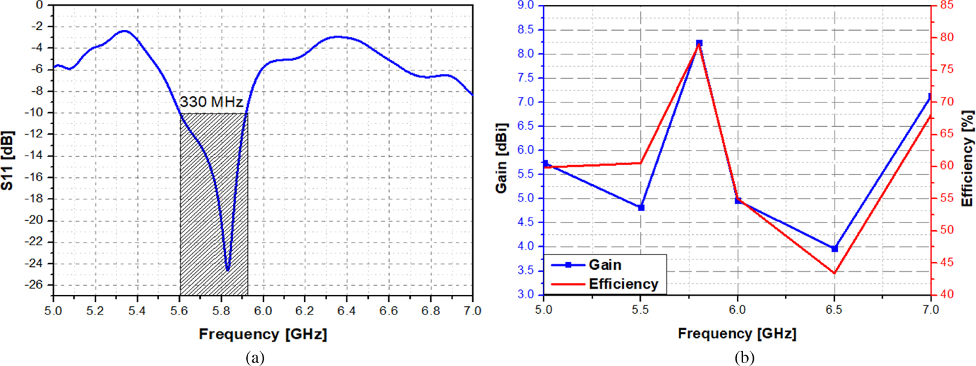
Fig. 7. (a) The reflection coefficient, (b) the gain and efficiency of the single array antenna.

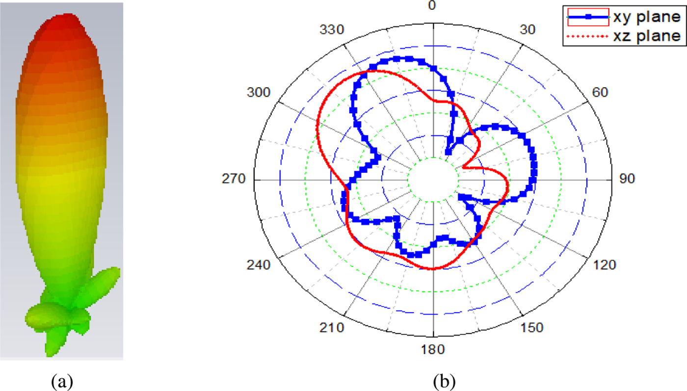
Fig. 8. The radiation pattern of the proposed array antenna: (a) 3D, (b) xy and xz planes.
From Figs 7 and 8, we can see that the bandwidth of the single antenna is approximately 330 MHz while the gain reaches 8.24 dBi. Here, the return loss of the antenna at the frequency 5.8 GHz is −24 dB. This indicates that the impedance matching of the antenna is quite good. In addition, the efficiency of the antenna gets 79%. Moreover, the antenna has a high directivity (10.45 dBi) and the low side lobe level (−8.1 dB). It can be seen that that the angular width (3 dB) is only 36.6°.
MIMO array antenna
To illustrate the effect of the proposed metamaterial structure on the parameters of antenna, this paper simulates in some cases: one substrate layer, two substrate layers, and two substrate layers with metamaterial structure.
Firstly, Fig. 9 shows the difference in the reflection coefficient in three cases. It is observed from this figure that there is a dramatical variance in the bandwidth of antenna in the cases where the bandwidth is the smallest when the antenna uses one substrate layer (140 MHz). This is reasonable because the antenna does not use any method to enhance the bandwidth. Therefore, the bandwidth is only one resonant mode. There is a slight improvement in the bandwidth of antenna in the case of the antenna using two substrate layers and this improvement is enhanced from an increase of the substrate height. However, the bandwidth of antenna is still one resonant mode. As a result, the bandwidth is only 250 MHz. When antenna uses two substrate layers with metamaterial structure, there is a significant improvement in the bandwidth of antenna. The bandwidth is not only enhanced from the increase of the substrate, but also from the use of metamaterial structure on the ground plane through created consecutive cavity resonators. In this case, the bandwidth includes three consecutive resonant modes. Therefore, the bandwidth of antenna reaches 1.78 GHz.
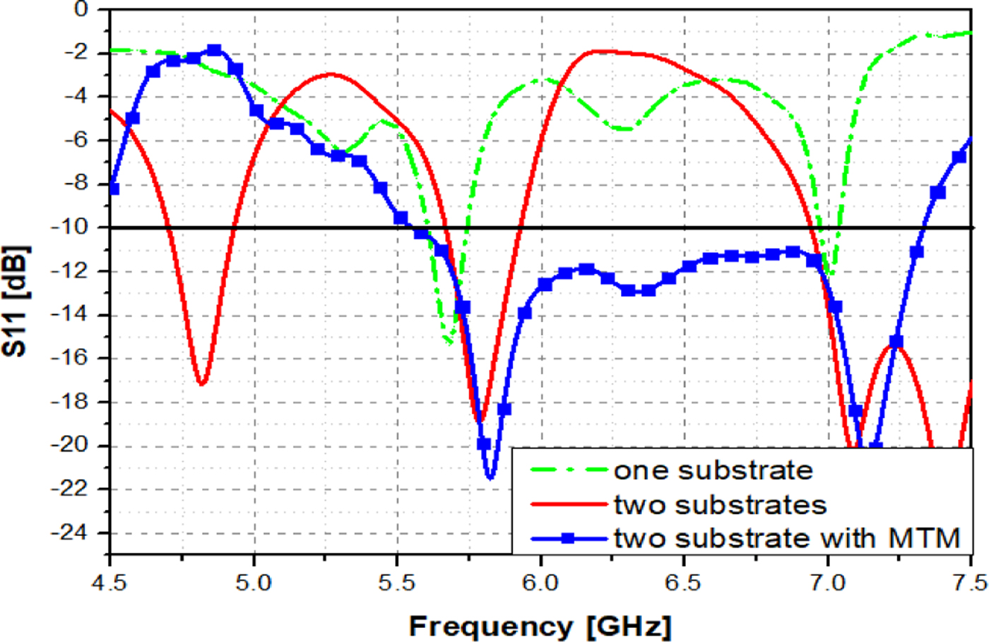
Fig. 9. The difference in the bandwidth of antenna in three cases: one substrate, two substrates, two substrates with MTM.
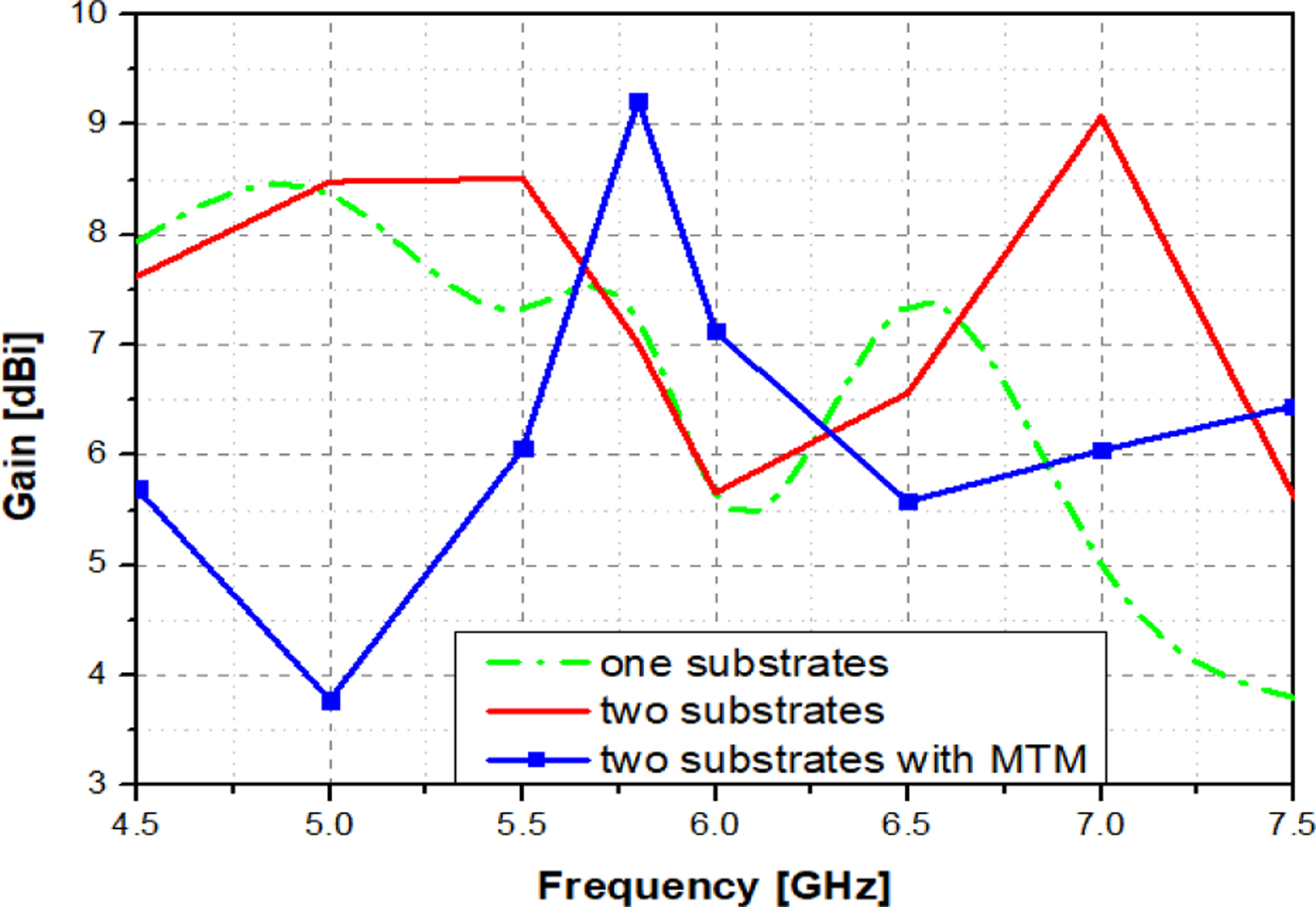
Using metamaterial structure on the ground plane not only improves bandwidth, but also enhances gain for antenna through current re-distribution. This is indicated in Fig. 10.

Fig. 10. The difference in the gain of the antenna in three cases: one substrate, two substrates, two substrates with MTM.
From Fig. 10, we can see that the gain of the antenna with two substrate layers with metamaterial structure is the highest pick (9.2 dBi) while in another case, the gain values of the antenna are only 7.22 and 7 dBi, respectively. It is clear that the gain of the antenna is significantly improved through current re-distribution. We know that radiation of the microstrip antenna is determined from the field distribution between the patch metallization and ground plane. In other words, the radiation can be described in terms of the surface current distribution on the patch metallization [Reference Ramesh Garg, Bhartia and Bahl21]. Based on the principle of gain enhancement for antenna using metamaterial structure is found in [Reference Van Yem and Lan22], and using the proposed metamaterial structure causes current re-distribution in antenna and this leads to interference between waves. This opens an opportunity to gain enhancement for the antenna. Here, the gain of the antenna is enhanced when we re-distribute current in order that more and more currents at where the phase shift is 0 (constructive interference) whereas in other places, there is a limitation (deconstructive interference). Then, not only the gain is improved, but also the directivity is still enhanced.
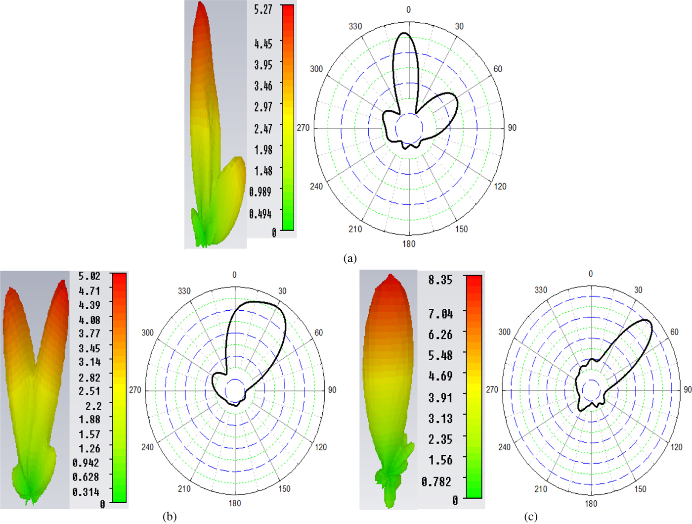
Figure 11 shows the difference in the radiation pattern of the antenna in three cases.

Fig. 11. The difference in the radiation pattern in three cases: (a) one substrate, (b) two substrates, and (c) two substrates with metamaterial.
It is clear that the difference in the radiation pattern between cases is clear. In two cases of one and two substrates, the directivity of the antenna is very low while the side lobe level is high. These are shown through the values of the main lobe magnitude that are 5.67 and 7.24 dB, respectively, and the side lobe levels are −2.5 and −6.7 dB. When the antenna uses two substrates and metamaterial structure, the parameters of antenna such as the main lobe magnitude and the directivity are 9.18 and 10.45 dBi. These show that using metamaterial structure to improve gain and bandwidth for antenna is the right method.
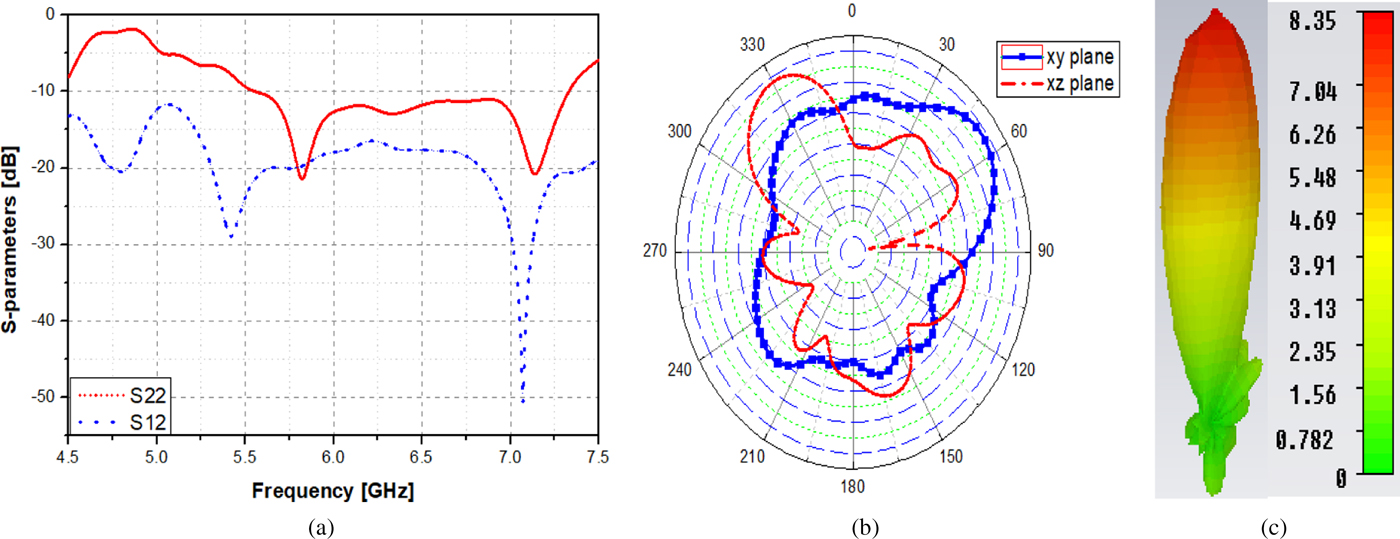
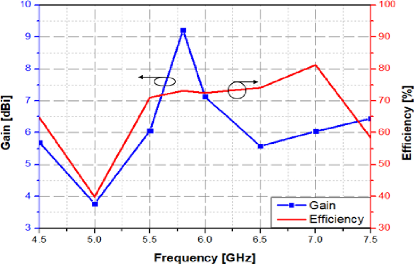
Figure 12 and Fig. 13 illustrate the simulated S-parameters, radiation pattern, and the normalized 5.8 GHz radiation pattern of the proposed antenna while Fig. 14 shows the gain and efficiency of the proposed antenna. From Fig. 12, we can see that the bandwidth of the proposed antenna is 1.8 GHz (at −10 dB) corresponding to the bandwidths in the percentage of approximately 31%. In addition, the isolation of the antenna is <−17 dB. Moreover, the gain of the antenna reaches 9.2 dBi while the efficiency is 73.14% (Fig. 14). Besides, another important parameter in the MIMO system to determine diversity performance is the envelope correlation coefficient (ECC). Here, ECC is defined as follows [Reference Su23, Reference Ibrahim, Abdalla and Hu24]:
 $${\bi \rho} _{\bi e} = \displaystyle{{{\vert {{\bi S}_{11}^{\bi {^\ast}} {\bi S}_{12} + {\bi S}_{21}^{\bi {^\ast}} {\bi S}_{22}} \vert } ^2} \over {\lpar {1-{\vert {{\bi S}_{11}} \vert }^2-{\vert {{\bi S}_{21}} \vert }^2} \rpar \lpar {1-{\vert {{\bi S}_{22}} \vert }^2-{\vert {{\bi S}_{12}} \vert }^2} \rpar }},$$
Fig. 12. The simulated results of the proposed MIMO antenna: (a) S-parameters, (b) xy and xz planes, 3D radiation.
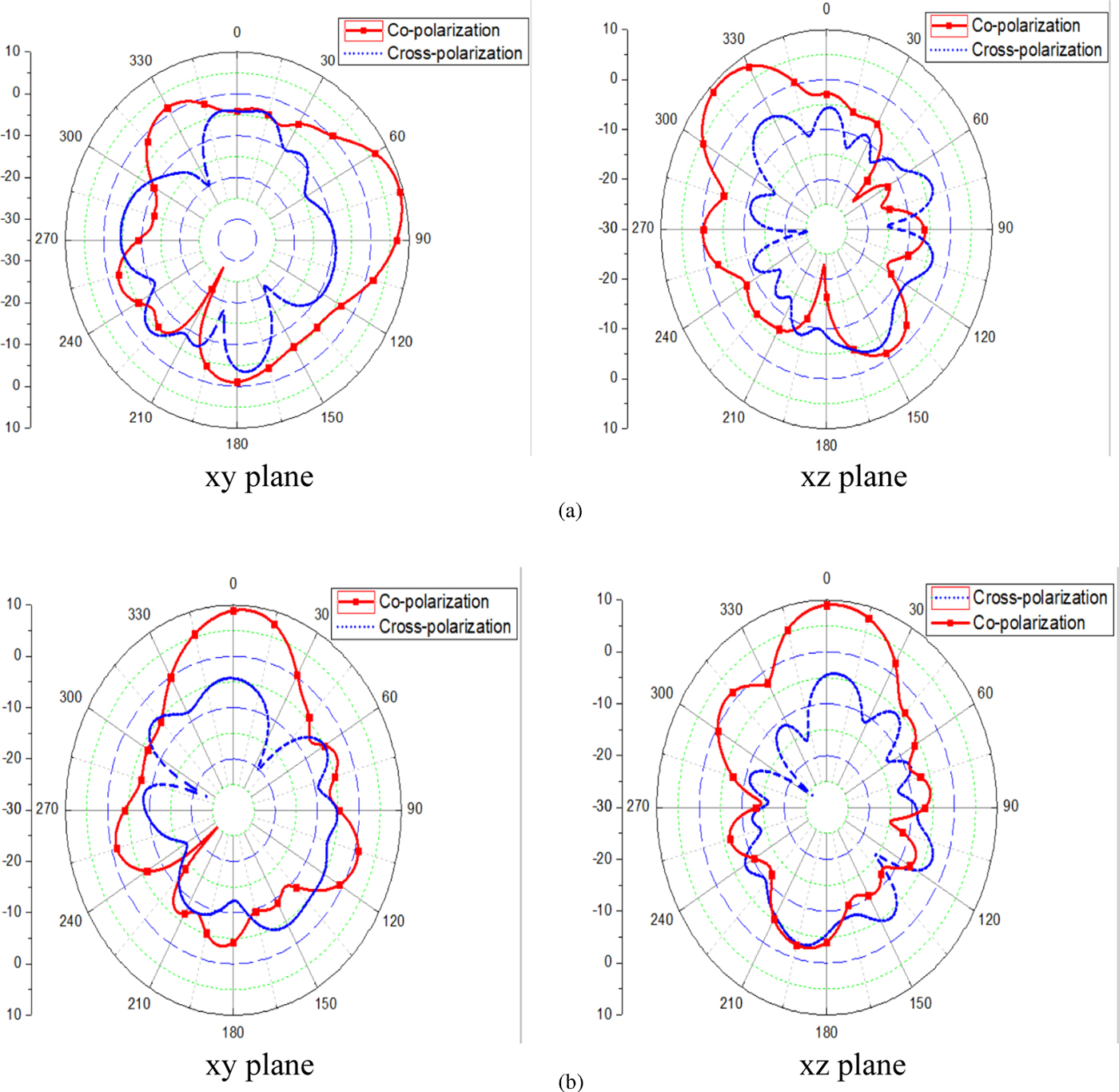
Fig. 13. The normalized 5.8 GHz radiation pattern of the proposed antenna: (a) Port 1, (b) Port 2.

Fig. 14. The gain and efficiency of the proposed antenna.
and the ECC also can be calculated using the radiation pattern as [Reference Ibrahim, Abdalla and Hu24]:
 $$ECC = \rho _e = \displaystyle{{{\left \vert {{\rm \int\!\!\!\int} 4\pi \lsqb {F_1\lpar {\theta, \varphi} \rpar \cdot F_2\lpar {\theta, \varphi} \rpar d{\rm \Omega}} \rsqb } \right \vert} ^2} \over {{\rm \int\!\!\!\int} 4\pi {\vert {F_1\lpar {\theta, \varphi} \rpar } \vert } ^2d{\rm \Omega} {\rm \int\!\!\!\int} 4\pi {\vert {F_2\lpar {\theta, \varphi} \rpar } \vert } ^2d{\rm \Omega}}}. $$
Figure 15 shows the ECC of the proposed array antennas. From this figure, the proposed antenna has the simulated ECC lower than 0.02 for a wide frequency range. This is suitable for application with a minimum acceptable ECC of 0.5 [Reference Karaboikis, Papamichael, Tsachtsiris, Soras and Makios25].
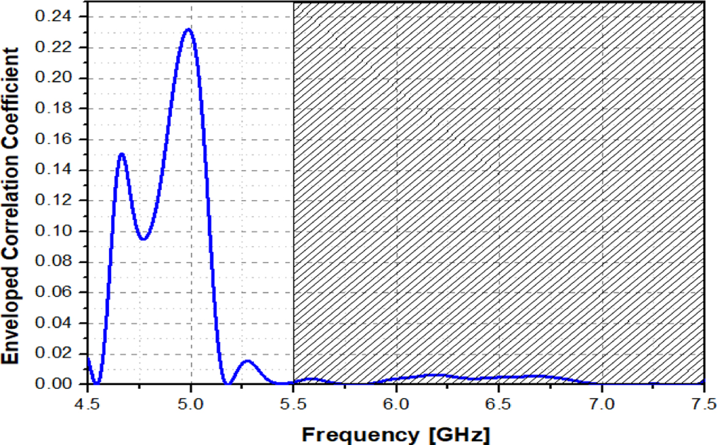
Fig. 15. The ECC of the proposed MIMO array antenna.
Measurement results
To verify the performance of the proposed MIMO array antenna for WLAN application, the prototypes of the MIMO array antenna, as shown in Fig. 16, were fabricated on Roger4350B substrate material with a permittivity of 3.66 and the thickness of 1.524 mm. The dimensions of antennas are 70 × 72 × 3.048 mm3 and 137 × 77 × 3.048 mm3, respectively. Figure 17 shows the measurement results of S-parameters of the single array antenna and MIMO array antennas. It can be seen that the bandwidths of the single array antenna and MIMO array antenna are 350 and 1780 MHz, respectively. Besides, the mutual coupling of the antenna is lesser than −18 dB.
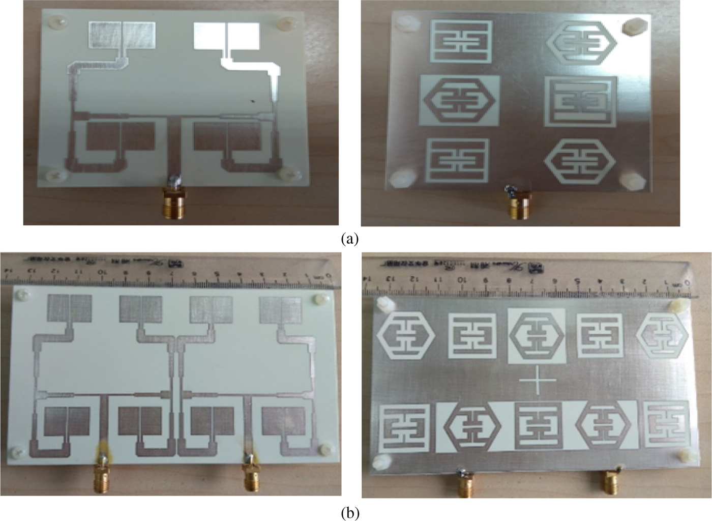
Fig. 16. The prototypes of the proposed MIMO antenna: (a) single array antenna, (b) MIMO array antenna.
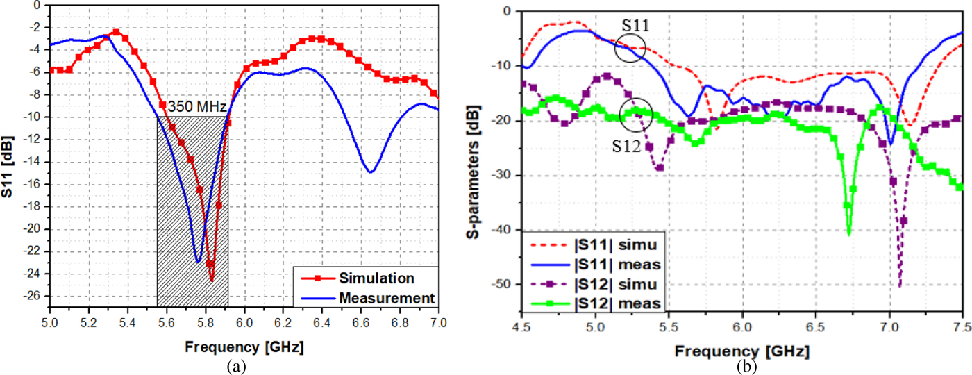
Fig. 17. Measurement results of the S-parameters: (a) single array antenna, (b) MIMO array antenna.
Figure 18 illustrates the measurement results of the gain of the proposed antenna. Here, the measurement results of gain of MIMO antenna and single array are 8.9 and 7.8 dBi while these values for simulation are 9.2 and 8.2 dBi, respectively. The results in this work have also been compared with the other works as shown in Table 4. Although the size of the proposed antenna is larger than the sizes in the references, the antennas in the references are single antenna instead of antenna array as the proposed paper. Therefore, this is acceptable. In addition, as can be seen that although the antenna in [Reference Ding, Gao, Qu and Yin26] has the large percentage of bandwidth (23.9%), the gain is only 5.5 dBi and the isolation of the antenna is only 17 dB. In other work [Reference Costa, Member, Lima, Medeiros, Fernandes and Member27], the gain and bandwidth percentage of the antennas are 7 dBi and 7.7%, respectively. Moreover, the isolation of the antenna in [Reference Costa, Member, Lima, Medeiros, Fernandes and Member27] is not good (14 dB). This also appears in [Reference Jehangir and Sharawi28] when the mutual coupling between antenna is very high (−12 dB). Besides, the bandwidth percentage and gain of this antenna are 8.8% and 4.3 dBi, respectively. Similarly, the antenna in [Reference Yang, Yan and Li29] and [Reference Pandit, Mohan and Ray30], the isolation between antenna is only 15 dB, while the gains of antennas are very low (lesser than 2 dBi).
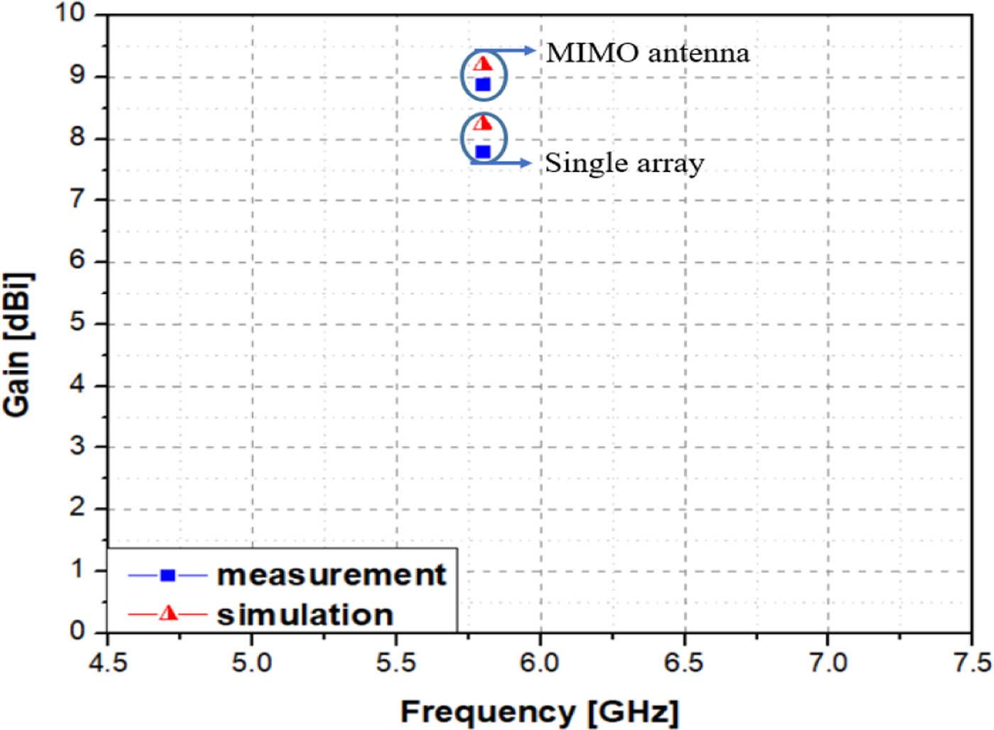
Fig. 18. The measurement results of gain for the proposed antennas.
Table 4. The comparison between references and this work

Meanwhile, the work in [Reference Malviya, Panigrahi and Kartikeyan31], the antenna includes two sets of two elements (1 × 2) and it is yielded at 5.8 GHz. Although the isolation of antenna is 34 dB, the gain and bandwidth percentage are low (7.8% and 5.3 dBi). In another aspect, the size of the antenna in [Reference Malviya, Panigrahi and Kartikeyan31] with two elements based on the substrate with higher dielectric constant (4.4) is smaller than our proposed antenna (with four elements and the dielectric constant of 3.66). We know that there is an inversely proportional relationship between the size of the antenna and the dielectric constant of the substrate [Reference Yohei, John, Volakis and Chen32]. In addition, the larger number of element also leads to increase the size of the antenna. Therefore, the size of the antenna in our paper is larger than the size in [Reference Malviya, Panigrahi and Kartikeyan31], this is understandable.
Conclusion
This paper has presented a MIMO array antenna for WLAN application in a compact size of 137 × 77 × 3.048 mm3. A metamaterial structure is proposed and it is applied to improve parameters of MIMO such as bandwidth, gain, and mutual coupling. Operating at 5.8 GHz, the proposed antenna gets wide bandwidth of 23.5%, high gain of 9.2 dBi, and good isolation of 18 dB. In addition, the antenna achieves a good radiation efficiency of 73%. The antenna prototypes were fabricated on Roger4350B and the antenna performances are verified through simulation and measurement. With the features of compact size, high gain and wide bandwidth, a planar structure and high isolation, the MIMO array antenna can be widely applied to WLAN applications.
Author ORCIDs
Nguyen Ngoc Lan, 0000-0001-8506-9979.
 Nguyen Ngoc Lan received Master degree from the School of Electronics and Telecommunications, Hanoi University of Science and Technology, in 2014. From 2015 to 2018, she was a Ph.D. student at the School of Electronics and Telecommunications, Hanoi University of Science and Technology, Vietnam. Her research interests are microstrip antenna, mutual coupling, MIMO antennas, array antennas, reconfigurable antennas, polarization antennas, metamaterial, metasurface.
 Vu Van Yem received Ph.D. degree from the Department of Electronics and Communications, TELECOM ParisTech, France, in 2005. From 2006 to 2007, he was a postdoctoral researcher at the Department of Hyper-Frequency, the Institute of Electronics and Microelectronics and Nano technology (IEMN), France. He has been qualified as an associate professor since 2009. He is the head of president's office as well as head of RF & Microwave Lab, Hanoi University of Science and Technology, Vietnam. His research interests are microwave engineering, antenna, chaos-based digital communications as well as advanced wireless communication and localization.