I. INTRODUCTION
For discovering the weather condition, detecting precipitation and assisting the researchers to make timely decisions, weather radars are designed. Weather radars detect precipitation in the atmosphere by emitting pulses of microwave and measuring the reflected signals from the center of precipitation. The distance between radar and the precipitation or clouds is determined from the time it takes for the microwave to travel to and from the clouds. Currently, several frequency bands are assigned to weather radars applications, including the S band (2−4 GHz), C band (4−8 GHz), and X band (8−12 GHz). In this research, the operating bandwidth ranges is C band, which appertain to the range frequency of IEEE 802.15a (3.1−10.6 GHz) covers the standard of the ultra wide band (UWB) [1–Reference Heinselman, Priegnitz, Manross, Smith and Adams2].
Use of UWB signals holds great promise with low power consumption for reliable wireless communication at high data rate.
In particular, a suitable UWB antenna should be capable of operating over an ultra-wide bandwidth (3.1–10.6 GHz) as allocated by the Federal Communications Commission and any signal that occupies a fraction bandwidth of 20% or greater can be used in UWB communication systems [Reference Boutejdar, Ibrahim and Burte3–Reference Siriwongpairat and Liu5].
For high gain and good directional beam-width, microstrip patch arrays antennas are extensively applied in radar systems, which are low cost, lightweight, low profile, and can accurately control radiation patterns [Reference Bernety, Gholami, Zakeri and Rostamian6–Reference Yaccoub, Jaoujal, Younssi, El Moussaoui and Aknin12].
Weather radars systems are composed of many different components, which are: wave form generator, transmitter, receiver, antenna, duplexer, and display unit. There is a great diversity in the design of radar systems, which depends on the purpose of the radar, but the fundamental operation and main set of components is the same, and Fig. 1 shows an example of weather radar components (Fig. 1). In this paper, our investigation focuses only on the antenna element, its miniaturization and optimization of its radiation performance [Reference Slimani, Bennani, El Alami and Harkat13].

Fig. 1. Typical Radar System.
This paper is a continuation of another work [Reference Slimani, Bennani, El Alami and Harkat14]. In this new study, we introduce planar patch array antennas, which consist of a 32 rectangular patch antenna elements with UWB characteristic for weather radar applications, which have high directional radiation characteristics and minimum group delay with maximum radiation along the desired directions [Reference Slimani, Bennani, El Alami and Harkat7, Reference Slimani, Bennani, El Alami and Harkat14]. In order to increase both directivity and bandwidth of the antenna, the type of substrate and the shape of the ground plane are carefully chosen and designed. The advantages of these array antennas consist of small size and simple structure.
This paper is organized as follows. In Section II, the proposed array antennas design geometry and the design techniques are presented. In Section III, we have done a discussion and comparison between simulation results. Finally in Section IV, a discussion and comparison between simulation results and experimental results have done.
II. UWB ARRAY ANTENNAS DESIGN
A) Techniques of matching
As we know, Microstrip lines are used for signal transmission, but the main aim is to deliver information from generator to receiver with minimal loss of energy. To achieve this transmission, the load should be well matched to the impedance of the microstrip line. There are many methods for impedance matching and one of the most important methods is through quarter wave transformer. The power divider with quarter wave-transformer impedance parts is used in this paper to divide the power equally to all patches elements (Fig. 2). In general, impedance adaptation is very important in microwave circuit design, it is relatively simple at a single frequency, but becomes very difficult if wideband matching is desired.

Fig. 2. Power divider with quarter wave-transformer impedance parts.
A standard T-junction power divider used to divide power equally to the left and right patch arrays antennas is shown in Fig. 3 [Reference Chorfi15]:
 $$Z_3 = \sqrt {\displaystyle{{Z_1.Z_4} \over 2}}. $$

Fig. 3. Standard T-junction power divider.
Feeding antenna may become quite complex in microstrip technology, which include several bends. In designing feed array antennas we have to consider reflection levels at and electrical lengths of the bends and removing a part of the area of metallization in the bend's corner can reduce the reflection level.
Mitring the bend reduces the area of metallization, and so removes the excess capacitance. The percentage mitre is the cut-away fraction of the diagonal between the inner and outer corners of the un-mitred bend (Fig. 4).

Fig. 4. Microstrip mitred bend.
The optimum mitre for a wide range of microstrip geometries has been determined experimentally by Douville and James [Reference Douville and James16]. They find that a good fit for the optimum percentage mitre is given by:
 $$M = \left( {\displaystyle{{{\rm 100}x} \over e}} \right){\rm \%} = (52 + 65{\rm \; ex}{\rm p}^{( - 1.35W_i/h)}){\rm \%,} $$
where, h is the thickness substrate,
W i /h ≥ 0.25 and the dielectric constant ε r ≤ 25.
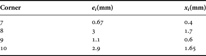
For this array antennas design, we give the e for each corner and we calculate the value of x by applying equation (2) and always we take this distance as the range between the point of internal corner and external corner. Table 1 shows the results obtained.
Table 1. Parameters corners of the proposed antenna.

Note i = 7, 8, 9, 10.
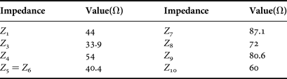
The microstrip lines impedances being used for feeding the elements of the array antennas are given in Table 2.
Table 2. Microstrip line impedances.
B) Material and geometry
The geometry of the proposed directional UWB array antennas is depicted in Fig. 5 with its characterizing parameters. The radiating elements are located on the x–y plane and the normal direction is parallel to z-axis. It is printed on FR-4 substrate with a dielectric ε r = 4.4, thickness h = 1.58 mm, and a loss tangent δ = 0.02, which is excited by a 50 Ωcoplanar waveguide (CPW) transmission line printed on a partial grounded substrate (Fig. 5).

Fig. 5. Geometry of proposed UWB array antennas, (a) top view, (b) edge view.
The choice of FR-4 substrate does not come by chance, but based on several recent papers, it is very much used in the UWB antenna due to its good adaptation and its low cost in the market [Reference Ibrahim, Abdalla and Boutejdar17–Reference Park, Li and Lin18].
Increasing of the substrate size does not affect the performance of the array antennas, but our aim is its miniaturization, which facilitates its implementation in any circuit of system Radar.
Table 3 shows the geometric parameters of our array antennas that have been calculated by use of the relation [Reference Slimani, Bennani, El Alami and Harkat10].
Table 3. Parameters of the proposed array antennas.

III. SIMULATION RESULTS AND DISCUSSION
In this section, we made a comparison between High Frequency Structure Simulator (HFSS) and CST simulation results of the based and proposed array antennas. The quarter-wave transformer is used along the lines of the feed array antennas to reduce the return loss and so as to find a proper feed location for better transmission between the feed port and radiating elements.
Initially the length of each section of the feed lines is taken as λg/4, but later we optimized them to give the minimum return loss for better matching. To minimize coupling between individual elements the separation is taken as λ/3 from their feed line where λ is the free space wavelength in mm.
This optimized distance is selected in order to achieve the minimum mutual coupling effect in the radiation pattern and to avoid grating lobes.
A) Return loss
Figure 6 exhibits the HFSS and CST simulation return losses versus frequency for the based [Reference Slimani, Bennani, El Alami and Harkat14] and the new array antennas, where some discrepancies between them may be mainly attributed to the method used by each software for the resolution of Maxwell equations.

Fig. 6. Comparison Return loss of arrays antennas.
It can be seen clearly that the impedance bandwidth of the arrays antennas with a good matching from 4 to 8 GHz, the return loss less than −10 dB having been achieved, is about 118% of bandwidth, which covers the standard of IEEE 802.15a (3.1–10.6 GHz).
B) Voltage standing wave ratio (VSWR)
The VSWR is another important property of antenna design. It gives an indication of how much of the received energy is absorbed by an incoming wave front, as opposed to being reflected. A perfectly matched antenna would have a VSWR less than 2, this value is used to calculate the bandwidth of any antenna.
The VSWR between HFSS and CST simulation as a function of frequency is given by Fig. 7. It is minimal at the range frequency of 4–8 GHz and less than 2 for these two array antennas.

Fig. 7. Comparison VSWR of arrays antennas.
C) Group delay
Group delay is one of the important parameters treated in UWB antennas. It represents the phase information with operating frequencies, such as the antenna should be able to transmit the electrical pulse with minimal distortion.
The calculated group delay of the proposed array antennas is shown in Fig. 8. In array antennas if the group delay variation exceeds more than 3 ns, phases are no more linear in far field and phase distortion occurs, which can cause a serious problem for UWB applications. The group delay results in Fig. 8 show that over the whole band is 2.5 ns, except at 6 GHz is ±4 ns, which is in acceptable limits.

Fig. 8. Comparison Group delay of arrays antennas.
D) Gain versus frequency
For weather radar antennas, more as the distance increases between the radar and the detected area, more as the gain becomes very important. So, for a far distance, we need an antenna with higher radiation performance.
The peak of gain for the array antennas is plotted and compared between the based and new array antennas in Fig. 9. It is observed that the new array antennas gain steadily increases with frequency and attains a peak of more than 16 dB in all range frequency.

Fig. 9. Comparison Gain versus frequency.
It can be seen that the planar array antennas has a good gain enhancement across the frequency band of interest (4−8 GHz).
E) Far field radiation pattern
The comparison of the far field gain between HFSS and CST of the proposed patch array antennas is plotted in polar coordinates at Fig. 10, for both the resonance frequency 6 and 8 GHz. Figures 10(a) and 10(c) show the polar gain radiation pattern in E-plane (x − z) while Figs 10(b) and 10(d) show the polar gain radiation pattern in H-plane(y − z).

Fig. 10. 2D Gain radiation pattern of the proposed array antennas.
In CST, and at the resonance frequency of 6 GHz, the array antennas gain, the half-power beamwidth and the side-lobe level in E-plane (x − z) were 18 dB, 11.6°, and 8.1 dB, respectively. The half-power beamwidth and side-lobe level in H-plane (y − z) were 7.8° and 6.4 dB, respectively. In HFSS, in E-plane the gain is about 24 dB, the half-power beamwidth is about 12.6° and the side-lobe level is approximately 13 dB. In H-plane, the half-power beamwidth and side-lobe level were 8.5° and 8.4 dB, respectively.
For the resonance frequency 8 GHz, in E-plane, the array antennas gain, half-power beamwidth and side-lobe level in CST and HFSS were 23.4 dB, 7.9°, and 4.6 dB, respectively. The half-power beamwidth and side-lobe level on H-plane were 6.8° and 4.3 dB, respectively.
According to the same figure, we find that the new array antennas have a bidirectional radiation pattern directed towards the desired End-Fire directions with minimum side lobes level in our resonance frequency.
F) Surface current distribution
Figure 11 illustrates the surface current distributions on the top patch array antennas in the both resonance frequencies 6 and 8 GHz, the red color indicates the maximum current density while the blue color indicates the minimum current density. As expected, strong surface current densities were present at the lower and upper resonance frequencies along the T-junction power divider region. When we are moving away from this cross-section, the current density decrease and the interaction vanishes rapidly because the distance increases from the point of excitation.

Fig. 11. Surface current distribution of the proposed array antennas.
So if we compared our work with some works that treat the arrays antennas with different geometries for RADAR applications [Reference Knott, Bertuch, Wilden, Peters, Brenner and Walterscheid19–Reference Kuo and Hwang21], we can conclude that the advantage of our array antennas consists of its small dimension compared to other geometries, the same for the radiation performance, such as the distribution of the far fields, the level and the number of side lobes are better than the radiation characteristics of other papers.
Finally, the proposed UWB array antennas presents the best performance in terms of adaptation, bandwidth and gain. Table 4 presents a comparison between HFSS and CST results of this work and other different work.
Table 4. Comparison result between HFSS and CST.

IV. FABRICATION AND EXPERIMENTAL RESULTS
In order to validate the simulated results, the array antennas were fabricated, where the prototype is connected to SMA-Female connector. It is tested using VNA-Network Analyzer at ESEO-EMC Laboratory in France (ESEO).
The array antennas designed with a partial ground plane was fabricated and their photos are shown in top and front view at Fig. 12.

Fig. 12. Fabricated array antennas with partial ground.
A) Return loss
The simulated and measured results of reflection coefficient for these planar patch array antennas are shown in Fig. 13.

Fig. 13. Comparison Return loss of arrays antennas.
It is observed that, the simulated impedance bandwidths (S 11 ≤ −10 dB) is about 118%, while the measured impedance bandwidth (S 11 ≤ −10 dB) is about 122% with several resonance frequencies close to 4, 4.5, 5.5, 7, 8, and 9 GHz. The impedance bandwidths of experimental result is able to cover the desired frequency band (4−8 GHz).
B) VSWR
The simulated and measured VSWR performances are plotted in Fig. 14. It is clear that the results show a good agreement and the difference between the measured and simulated VSWR as well as the frequency shifts are caused by the slight fabrication and measurement error.

Fig. 14. Comparison VSWR of arrays antennas.
Finally, the proposed UWB array antennas present the best performance in terms of adaptation, resonant frequency, and bandwidth. These performances are summarized in Table 5.
Table 5. Comparison between measured and simulated results.

V. CONCLUSION
A planar microstrip array antennas of 32-element with very high radiation performance for weather radar applications was designed and measured. By using T-divider power technology, the input power was divided to the patch elements equally. The effect of the radiation from the feed lines is very negligible and the radiation only comes from the patch elements. The simulated and measured results showed that the bandwidth of this new array antennas is greater than 118% at −10 dB.
The high performance of gain, good beam steering, and the quite stable group delay over an ultra wide frequency range from 4 GHz to upper than 8 GHz are benefits this array antennas to be a good candidate in C-band weather radar systems.
ACKNOWLEDGEMENTS
Our sincere thanks to the Faculty of Sciences and Technics of Fez, University Sidi Mohamed Ben Abdellah, Morocco, for providing us an opportunity to carry out our said work in a well-equipped laboratory (L.E.R.S.I). We are also thankful to all our colleagues who helped us while we were working on this project.
 Abdellatif Slimani was born in Erfoud, Morocco in 1989. He received his license degree in Engineering Science from the University of Moulay Ismail, faculty of science and technical Errachidia in the year 2011, and he received his Master's degree in Telecommunication and Microwave Devices from the University of Sidi Mohamed Ben Abdelah, National School of Applied Sciences Fez in the year 2013. His research interests include optimization, development and parametric performance study of arrays antennas for ultra wide band telecommunication systems.
 Saad Dosse Bennani born in Fez, Morocco in 1967, is Doctorate in Electronic and Signal Processing from the University Sidi Mohamed Ben Abdellah, Fez, Morocco. He is a researcher in the areas of antennas for telecoms application, shielded transmission lines and Professor in National School of Applied Sciences. He is a member of CMT 2010 & 2012 and co-chair of WITS-2014 & WITS-2015.
 Ali El Alami born in Morocco is Doctorate in Telecommunications and Electromagnetic Compatibility from the University Sidi Mohamed Ben Abdellah, Faculty of Sciences and Technics in Fez-Morocco. His research interests include numerical method, electromagnetic, microwave antennas, RFID systems, electromagnetic compatibility, RF and microwave applications.
 Mohamed Amellal born in Morocco, in 1985, is Doctorate in Electronic and Telecommunications from the European University of Brittany and the University Sidi Mohamed Ben Abdellah in Fez-Morocco. He received his Master's degree in Microelectronics for telecommunication and industrial process from University of Science and Technology Fez.