


I. INTRODUCTION
Digital radio-communications in S and C bands are evolving to very-high-data-rate transfer and robust transmission schemes, in response to users' needs for multimedia applications. The use of orthogonal frequency division multiplex (OFDM) and other multi-carrier solutions is very popular in 802.11a/b/g, Wifi 2.45 and 5.2 GHz, WiMAX, or other mobile cellular or connectivity wireless local area networks (WLAN) standards. Although these modulation schemes are spectral efficient, a high penalty is due to the peak-to-average power ratio (PAPR) of the emitted signals, causing unavoidable and crippling non-linearities (NL) [Reference Colantonio, Gianini and Limiti1–Reference Diet, Robert, Suárez, Valenta, Montes, Ripoll, Villegas and Baudoin10]. The emission of such high PAPR signals is a major design challenge of the front end (FE), due to the power amplifier (PA) impact in terms of efficiency and linearity. In that context, cognitive radio is a concept of a self-reconfigurable and highly flexible communication system driving to major improvements of the radio frequency (RF) FE of wireless transceivers. The preferred term for the RF part design challenge is multi-radio. The multiplicity of radio specifications shares part of the multi-radio transmitter concept, whose idea is to adapt to the several RF parameters of the standard specifications that differ principally by their modulation schemes (often high amplitude variation with OFDM), bandwidth (low, high, or very high data rate up to 100 MHz), their center frequency (from 800 MHz to 6 GHz), and the average power control (tens of dB) [Reference Baudoin, Berland, Vilegas and Diet4, Reference Chawanonphithak, Phongcharoenpanish, Kosulvit and Krairiksh6, Reference Choi, Yim, Yang, Kim, Cha, Kang, Kim and Kim7, Reference Diet, Azoulay, Joisel and Duchêne9, Reference Diet, Robert, Ribière-Tharaud, Villegas and Baudoin11, Reference Grebennikov12]. There have been many studies on the linear amplification of high dynamic signals. Actual popular techniques are based on linearization of the architecture with a decomposition and recombination of the information, for example, the envelope elimination and restoration (EER) presented in [Reference Chawanonphithak and Phongcharoenpanish5] and studied in [Reference Bahl2–Reference Baudoin, Berland, Vilegas and Diet4, Reference Chawanonphithak, Phongcharoenpanish, Kosulvit and Krairiksh6, Reference Diet, Azoulay, Joisel and Duchêne9, Reference Diet, Robert, Ribière-Tharaud, Villegas and Baudoin11] where the use of a high-efficiency PA (HPA) enables a high efficiency for PAPR in the range of 16 dB. A lot of improvements of EER-based architectures were recently proposed (also called polar architecture) where the envelope, or a part of it, is often coded [ΣΔ/PWM (pulse width modulation),] and restored by supply modulation or by multiplying the RF signal directly, before the PA, and filtering it after the power amplification [Reference Sokal and Sokal21]. Moreover, this implies filtering before the antenna and the overall efficiency will be lowered by the coding efficiency. Our interest in the paper concerned is that this filter process can be partially done, thanks to the output network of a switched mode PA, and so filtering needs would be relaxed by the antenna characteristic [Reference Bao and Ammann3, Reference Choi, Yim, Yang, Kim, Cha, Kang, Kim and Kim7, Reference Diet, Azoulay, Joisel and Duchêne9].
The idea for the design of the multi-radio EER/polar transmitter is to build a highly efficient linear FE that can adapt to several standards such as UMTS, WiFi, Wimax, and so on. Different bandwidths at the emission between 800 MHz and 6 GHz are needed: [0.8–1.1], [1.7–2.2], [2.4–2.7], [3.4–3.8], and [5.1–5.9] GHz. Herein we keep the principle of EER-based architecture where the envelope is modulated in order to drive the HPA with a quasi-constant envelope signal, and thus designed a switched mode filtering PA. As switched PAs enable a quasi-linear variation of the output voltage in function of the supply voltage, power control can be done in this way. Supply voltage variation is also a solution for amplitude modulation of such PAs. This can improve the linearity performance of the FE. Frequency flexibility depends on the output filtering networks. Reconstruction/restoration of the amplitude information is accomplished at emission, thanks to a pass-band profile of the FE (i.e. PA + antenna). The difficulty is to cover the multi-band specifications respecting the other standards used (immunity, co-existence). Figure 1 illustrates the proposed FE approach. Considered specifications are: carrier frequency, average power control, and adaptability to high PAPR modulation schemes with restoration of the amplitude/envelope information at the emission. The latter is accomplished, thanks to the coding of the envelope and the filtering of the switched HPA output network combined with the antenna. Frequency of operation is searched to be parameterized for flexibility (multi-radio figure of merit). The average power control can also be done with a slow voltage supply modulation if the PA is a saturated or switched mode one, as was already demonstrated in such an EER transmitter. The antenna with a multi-band profile would, in a first approach, be wideband, enabling a parameterization of notching bands. As the emission profile of the transmitter is multi-band, the HPA output network and the antenna should also have this quality. This multi-band profile, reported on both the PA and the antenna, helps in envelope restoration (ideally done with a bandpass filter) and lowers the constraints, and theoretically relax filtering selectivity, needed to be compliant with standard emission mask (adjacent channel power ratio values). Designing the filter, or a filter bank, for multi-radio architecture is a technical challenge, because the technological choice (integrated solution is preferred) should be compliant with the desired flexibility/accordability (multi-bands) and maximum insertion losses.

Fig. 1. FE idea for the multi-radio.
Section II of the paper is a presentation of the frequency flexibility of a class E PA. The class E PA was chosen as a highly efficient switched PA with a few reactive elements in its output filtering network. For multi-band optimization, we would increase the number of reactive elements of such PA in order to adapt the class of operation at different frequencies. The design of a PA based on a true non-linear (NL) transistor model is used for the simulation.
Section III is dedicated to the design of a wideband reference printed/planar antenna (compacted Vivaldi here) and its effect while loading the class E PA, with and without a notch between two bands of interest (WiMAX centered at 3.7 GHz and WiFi5 centered at 5 GHz). This antenna was realized and measured in order to incorporate its measurements under AGILENT ADS with the NL model of the transistor (PA co-simulation).
Section IV presents performances of the architecture in terms of efficiency while loading the PA with such antennas. It also illustrates the envelope restoration processing when considering a propagation channel (two notched antennas).
Section V synthesizes the results of the paper. The interest here was to present a potential solution for multi-radio transmitter architecture. The use of a polar/EER-based structure with “tuned” switched (SW) PA is interesting because it potentially fulfills several requirements of a multi-radio architecture at the same time, such as efficiency, linearity, frequency flexibility, and power control. The use of polar structure is also interesting for different modulation schemes. Currently envelope coding is mainly discussed by the community, and the use of SW PA associated with a pass-band profiled antenna (also wideband antenna with notch) is demonstrated here as a benefit because it helps to restore an AM information. This AM information is coded in order to provide a constant envelope RF driving signal for the PA and improving the FE efficiency. This results in relaxing the filter selectivity need and helps in lowering the spectral regrowth (limited by the standards emission masks). One major conclusion of this paper is that the antenna helps the envelope restoration, thanks to its notch and should be incorporated in the design optimization of such multi-bands systems, because its out-of-band characteristics influence the FE performances.
II. TUNING A CLASS E PA
The proposed architecture has the advantage of high efficiency whatever the signal dynamic is (not only peak efficiency) because the PA is a switched mode one. This quality is achieved for saturated and switched transistors. Switched and saturated classes of operation are composed by classes D, S, E, or F ones [Reference Diet, Berland, Villegas and Baudoin8, Reference Diet, Robert, Suárez, Valenta, Montes, Ripoll, Villegas and Baudoin10, Reference Kahn13–Reference Baudoin, Villegas, Suarez, Diet and Robert15]. Classes D and S are PAs dedicated to an amplification associated with a selective filtering: driving signals are often supposed to be “squared” as class S for PWM signals. These classes are hardly suitable for a multi-band profile use (but not impossible). Classes E and F are good candidates for RF PAs in EER/polar architecture. Class F is not considered here because it is based on several resonating elements tuned at a fixed frequency. Difficulty of detuning a network with a high number of components would result in a damaging and crippling increase of the filter sensibility. Possibility of detuning a designed class E PA is reported as was investigated in [Reference Bao and Ammann3]. The idea is to switch parallel capacitors in order to lower the frequency of the operation. One major difficulty is that the class E frequency of operation is not the resonating frequency of the output network, because the load presents an inductive part.
Class E PA was presented in [Reference Diet, Robert, Suárez, Valenta, Montes, Ripoll, Villegas and Baudoin10] where its operation is described as the optimization of design criteria such as non-overlapping voltage and current shapes in the switched transistor, nulling the first derivate of the drain voltage at the switching time, a capacitive shunting that absorbs the drain parasitic capacitance, etc. This results in a reactive load at the fundamental frequency and the harmonics. Design equations has been highly discussed and others topologies proposed [Reference Diet, Berland, Villegas and Baudoin8, Reference Baudoin, Villegas, Suarez, Diet and Robert15]. Principally, we can consider two main topologies as described in [Reference Bao and Ammann3] where the flexibility in frequency is investigated by the addition of a switched parallel capacitor. The first topology is presented as the classical serial inductor class E topology whose idealized equations (1) and (2) are summarized by Fig. 2 and its following equations, based on the works of Sokal et al. [Reference Diet, Robert, Suárez, Valenta, Montes, Ripoll, Villegas and Baudoin10] and Raab et al. [Reference Diet, Berland, Villegas and Baudoin8]:
 $$\left. {\matrix{ {R_1=\displaystyle{{V_{DC}^2 } \over {P_{RFout} }}0.5728\comma \; } \cr {L_1=\displaystyle{{R_1 } \over {\omega _{RF} }}1.152\comma \; } \cr {C_1=\displaystyle{{0.1836} \over {R_1 \omega _{RF} }}\comma \; } \cr } } \right]$$
 $$\left. {\matrix{ {R_2=\displaystyle{{V_{DC}^2 } \over {P_{RFout} }}1.365\comma \; } \cr {L_2=\displaystyle{{R_2 } \over {\omega _{RF} }}0.732\comma \; } \cr {C_2=\displaystyle{{0.685} \over {R_2 \omega _{RF} }}.} \cr } } \right]$$
Fig. 2. Topologies “1” and “2” for the class E, serial (top) and parallel inductor (bottom).
As can be seen, the first topology uses a Π network and needs a polarization inductance for the drain voltage supply. An equivalent RF schematic is thus composed of the RF switch (the transistor) and the Π network composed by Z p, Z s, and the load resistance Z ch (=R 1). At the RF frequency of switching, L 0 − C 0 can be avoided. The second topology is presented as the parallel tuned HPA [Reference Baudoin, Villegas, Suarez, Diet and Robert15]. Its design uses a parallel inductor in order to suppress the polarization inductance. This topology is illustrated in Fig. 2, and, dedicated optimum values for the load resistance R 2 and parallel capacitor C 2 and inductor L 2, based on the works of Grebennikov [Reference Baudoin, Villegas, Suarez, Diet and Robert15]. As was the case with regard to the first topology, the equivalent RF circuit consists of a switched transistor and a Π network with parallel, serial, and load impedance (Z p, Z s, and Z ch) whose expressions depend on the topology. It has been demonstrated in [Reference Bao and Ammann3] that the parallel topology is the best suited for detuning. The idea of a flexible class E parallel inductor topology (n°2) lies on the modification of its resonating frequency by adding a parallel capacitor with other RF transistors used as switched. The optimal impedance, at ω RF, to present at the output of the transistor (driven as a switch) is expressed as Z in2(ω RF) by
 $$\eqalign{Z_{in2} \lpar \omega _{RF} \rpar & =R_2 \displaystyle{{x_2^2+j\lpar x_2 - b_2 \, x_2^2 \rpar \over 1 - 2 x_2 b_2+x_2^2 \lpar 1+b_2^2 \rpar}}\comma \; \cr Z_{in2} \lpar \omega_{RF} \rpar &=R_2 \left[{ 0.6831+j0.4653} \right] = 0.8265\, R_2 e^{\ j 34^{\circ}.}}$$
To evaluate the modification of the optimal frequency of operation, we define a matching parameter in (4) with reference equal to the optimal impedance: Z opt = Z in(ω wanted) given in (3):
 $$\Gamma_{class \,E \hfill \atop with \, R_2 \hfill} \left(Z \right) = {Z - Z^{\ast }_{opt} \over {Z+Z_{opt} }} = {Z-0.8265\, R_2\, e^{-j 34{\circ}} \over Z+0.8265\, R_2 \,e^{j 34{\circ}}}.$$
The next step in our study is to consider the NL model of a transistor at such frequencies and modify its loading network with a reactive component (shunt capacitor), targeting the optimal class E impedance at different frequencies (WiMAX 3.7 GHz and Wifi 5.2 GHz). The transistor used to conceive the FE is a GaAs E-PHEMT, Avago ATF50189. It is a high-linearity, medium-power FET (29 dBm output power, 15.5 dB gain and 62% PAE at P1 dB compression point, in class A configuration). Maximum VDS and VGS allowed voltages are, respectively, 7 and 0.8 V. The threshold biasing voltage is 0.12 V for VGS. A trade-off must be done for the value of VDS, since a high value will allow a high gain, but a lower efficiency and a low value will have the counter-effect. A VDS voltage of 3 V was thus chosen as the best compromise. To illustrate the theory reported in Fig. 2 (values of R 2, C 2, and L 2), a class E amplifier was conceived to work at 3.7 GHz. The test signal is a 0.68 V amplitude signal, providing through the amplifier, a 23.4 dBm output power with 96.92% drain efficiency. The theoretical output power is 23.9 dBm which is quite close from the simulated value.
To definitively validate the class E behavior, load lines are plotted, with drain current and voltage, in Fig. 3. These results help in identifying the switching operation of the amplifier. The real model of the transistor mainly introduces a serial resistance R DS in parallel with the parasitic capacitor C DS at “on” state for the switch. At “off” state, the transistor may be abusively considered as C DS only for simplicity. The C DS value (1.3 pF) appears to be higher than the C shunt capacitance value. From this consideration it can be decided to consider both capacitances as one (C DS). Performances obtained are slightly lower with 21.6 dBm output power and 78.6% drain efficiency at the same frequency of operation. This non-ideal phenomenon can also be observed looking at the load line, showing switching imperfection in Fig. 3: the load “line” is a circle, and negative current occurs due to the discharge of the capacitor (C shunt + C DS). Using a non-ideal model, at RF frequencies, modifies the performances significantly, since the impedance seen by the transistor output is not the optimal impedance Z opt = 0.6831R 2 + jR 20.4653 (where R 2 is the load). This will have a strong impact while re-designing the output network with additional shunt capacitance for detuning.

Fig. 3. Transistor load line (left) and drain voltage and current(right). VDS = 1, 2 and 3 V.
The idea is to limit the number of reactive components of the class E output network while detuning the PA. To observe the shifting of the operation frequency while keeping the optimal impedance for a class E, we derive a frequency simulation and process the matching coefficient defined by (4) (see Fig. 4). It is important to note that the matched point on the smith chart means “Z opt” and not 50 Ω. Qualitatively, two values of the capacitor demonstrate the theoretical shift (detuning) of the optimal frequency in Fig. 4. At such frequencies, the output of the E_PHEMT (GaAs, Avago ATF50189), used as a switch, can be modeled by a parallel capacitance of 2.5 pF. Starting the simulation with optimal class E output network values for 5.2 GHz, the addition of shunt capacitor lowers the optimum frequency for switching the transistor (optimum frequency of the PA). Capacitors are slowly controlled (DC) by hard-driven transistors (referred to as DC switched transistor here). Results of matching coefficient defined by (4) are reported in Fig. 4 where the tuning possibility is illustrated for the WiMAX (3.7 GHz) and the Wifi 5.2 GHz. In Fig. 4, S11 is the matching coefficient defined in (4) for the state “off” of the DC switched transistor and S22 is the coefficient for the state “on”. The addition of a parallel capacitance (by switching “on” the DC switched transistor) decreases the frequency of operation.

Fig. 4. Tuning of the parallel topology, thanks to the DC switched transistor (two states). S parameters are computed with Z 0 = Z opt.
The following step is to consider the NL model in a transient analysis with the switched capacitor (see Fig. 5). Also, characteristics corresponding to a true antenna load are introduced in the transient simulation. The antenna conception with CST is the subject of the following part. Results of antenna influence as loads in the transient simulation illustrated in Fig. 5 are given at the end of the next part.

Fig. 5. Topology of the SW PA with DC switched transistor (capacitor in series) and influence of antenna out-of-band characteristic.
III. ANTENNA DESIGN
The performance of the FE, once linearity requirements are fulfilled, is evaluated in terms of efficiency, that is to say the real power transmitted and radiated by the antenna compared to the DC power. To be compliant with the multi-radio concept, the antenna should provide a multi-band profile without lowering the PA efficiency in each sub-band. Connecting several antennas (multi-antennas) could be a solution, but is subject to important losses when combining. The solution investigated here is the design of a single antenna connected to the multi-band PA. The basic idea of the antenna design is to use a simple and low-cost structure providing a flexible parameter in case of the modification of the multi-band profile. It is expected for future works to be able to produce multiple rejections by addition of rejection parameters (i.e. slots for radiating structures) and hence we choose to design firstly an antenna with wideband property and adding some modification to tune the possible rejections. Based on a ultra Wide Band (UWB) approach with introduction of notching [Reference Jeong and Wang16–Reference Schantz20], we decide to design a Vivaldi printed antenna with and without a slot for notching the spectrum between WiMAX and Wifi5 band. The designed structure is simulated under CST with AR320 substrate (0.8 mm) and 35 µm copper. The first approach was to adapt the Vivaldi antenna on a maximum of 9 × 9 cm2 surface and to feed the slot of the antenna to obtain a return loss of −12 dB between 2 and 6 GHz. The feeding point is accomplished with a coupling back-sided as is reported in Fig. 6 (the dimensions are also given). In Fig. 6, the return loss for the Vivaldi antenna with and without a slot for notching is drawn. This notching produces a rejection between 3.8 and 4.7 GHz with a maximum of almost −2 dB. One advantage of the Vivaldi is that the direction of the main lobe is kept constant irrespective of the frequency. The Vivaldi antenna radiation pattern is near from a constant aperture antenna, that is to say the gain of the antenna is increasing with the frequency in the same direction.

Fig. 6. Vivaldi printed antenna on AR320 (top). Return loss (frequency in GHz) for the antenna with/without rejection slot (notch).
In order to confirm the influence of the antenna on the FE performance, their reflexion coefficients (return loss) were reintroduced as a realistic load of the amplifier designed with the transistor model, under AGILENT-ADS. This is illustrated by plotting the matching coefficient defined in (4) for different loads: 50 Ω, the Vivaldi antenna with and without the slot. Results are shown in Fig. 7, where it can be observed that the flexibility is conserved but the influence of the frequency characteristic, especially in “out of band”, of the load can cause a shift in the optimal frequency of operation. This points out that the class E amplifier is designed at an optimum frequency but its voltage and current shapes at the drain of the transistor are not a single-tone signal and directly determine the efficiency of the amplification process. Figure 7 shows that the detuning is conserved for a great part. The frequency characteristic of the antenna also has an important influence on the output network of the PA, even if the return loss is below −10 dB, and can shift the optimal frequency and/or eliminate the possibility of optimal impedance value (matching coefficient superior to −12 dB, for example). The slot rejection has an important influence on the PA and can produce some localized sub-optimal frequencies of operation by impedance transformation (LC filtering network of the PA).

Fig. 7. Matching coefficient, in dB, for optimal class E (detuning) and for: 50 Ω, Vivaldi antennas without and with rejection slot.
These antennas are designed to be integrated into the FE. We introduced their frequency parameters under AGILENT ADS in the following part in two steps: (i) loading by the antennas as developed in this part, and (ii) simulating a propagation channel between two antennas in line of sight, as will be shown in the following part.
To conclude, this part demonstrates the importance to take into account the load of the antenna in addition to the NL transistor behavior in the design of a multi-band FE. The following part will present the performance of the FE in terms of efficiency, thanks to transient co-simulation under AGILENT ADS.
IV. FRONT-END CO-SIMULATION
Antennas S parameters matrix is introduced as a load in a transient simulation with the transistor NL model. The co-simulation is computed for the different loads in the two frequency configurations, 3.7 and 5.2 GHz following the state of the DC switched second transistor in the output network. A variation of the supply voltage of the transistor between 1 and 3 V (9.5 dB) is performed in order to illustrate the feasibility of the average power control while keeping the same efficiency (benefit of using switched PA for polar transmitters/FEs). Results of efficiency calculation are reported in Fig. 8. It is important to note, for each case, the presence of two high-efficiency bands of operation. There is a slight shift in optimal frequency for maximum efficiency when loading by the Vivaldi antennas. The typical high performance of such PA at these frequencies is about 80%, due to the transistor non-idealities for fast switching. Our results are satisfying with regard to its output capacitance value (several pF).

Fig. 8. Efficiencies for 50 Ω load (top), and the two Vivaldi without (middle) and with the rejection (bottom) in function of the frequency. Efficiency is calculated for 1, 2, and 3 V supply.
In order to illustrate the transmission of amplitude information (the envelope coded and recombined), thanks to the pass-band profile of the FE (PA + antenna), we simulate with CST the propagation channel, represented in Fig. 9, and introduce the four S parameters in the transient AGILENT ADS simulation. Figure 9 illustrates a simulation between two slotted Vivaldi antennas in line of sight at a distance of 70 cm (enough to consider the radiation hypothesis). The emission of an envelope restored on the signal is a subject of research in this type of architecture because the entire spectrum of the PA driving signal is not a “useful” information. If the FE identified here as PA + antenna is not providing a pass-band profile function as well as amplification, some unwanted and un-allowed spectral re-growths will be crippling as it is confirmed by the results of [Reference Diet, Azoulay, Joisel and Duchêne9].

Fig. 9. Propagation channel (measures from one antenna to another). Principle of the simulation for validation of AM transmission.
The idea of constant amplitude scenario is to simulate the envelope coding by multiplying the driven signal of the PA with a modulating square ±1, which is in fact represented here by a simple Binary Phase Shift Keying (BPSK) modulation where the amplitude information is the average of the signal (here a simple sinus). Results of the FE simulation through the propagation channel in the cases of two Vivaldi antennas with and without rejection slots are reported in Fig. 10 for the 3.7 GHz case (3 V supply voltage).

Fig. 10. Transient co-simulation : driving BPSK-modulated signal (top/first), modulating information (second), transmitted signals at the TX antennas without (third) and with (fourth) the rejection slot and received signals after the free space propagation channel and RX antennas with (fifth) and without (sixth/last) rejection slot.
Results in Fig. 10 are pointing to the high influence of the rejection profile and its benefits, because the received signal is presenting a restoration of the amplitude information without adding any filter between the PA and the antenna. The possibility of minimizing the filtering constraints (selectivity, losses, etc.) at the emission for the same power and efficiency is observed in that manner. The plotting of the antenna's driving signals in Fig. 10 illustrates the pass-band property of the PA that helps the restoration of the amplitude information. This restoration is to be completed at the emission and lies on both PA and slotted antenna contributions.
This FE offers high efficiency and it is possible to transmit AM information by coding it in the RF PA driving signal. The filtering decoder is the restoration process accomplished by the emitting and receiving antennas.
If the spectral emission requirements are fulfilled, the linearity of the FE can be observed by comparison of the emitting information before coding (average value of AM signals in Fig. 10) and the envelope of the received signal (RX signal, antenna W. slot in Fig. 10). We simulate a more realistic AM variation in Fig. 11 and observed the two signals mentioned above. In that simulation, there are three periods:
– From 5 to 10 ns, no AM variation is transmitted.
– From 10 to 19 ns, the RF driving signal of the PA is phase modulated in order to simulate the envelope coding discussed in the previous parts and illustrated in Fig. 10.
– From 19 to 30 ns, a variation of the supply voltage is added and the received signal presents the resulting combination (multiplication) of both modulating signals.
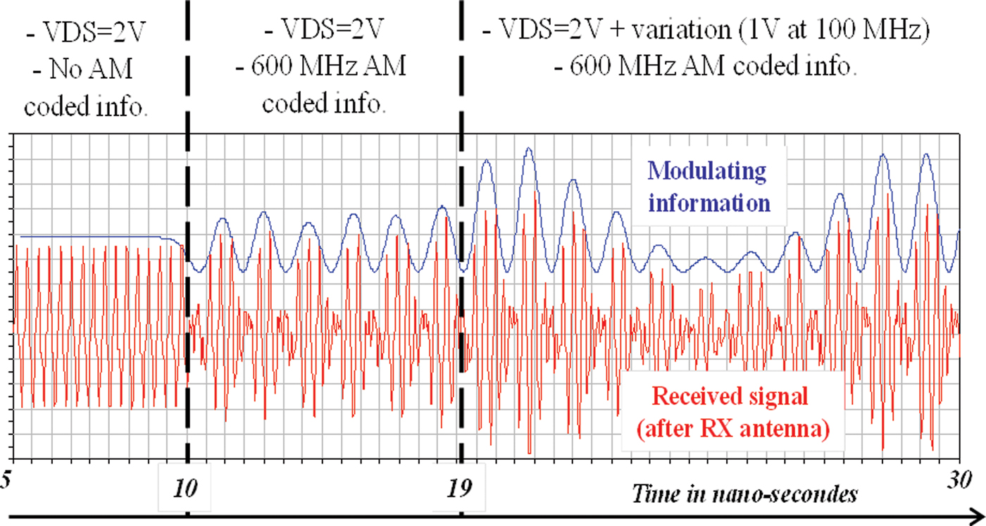
Fig. 11. Modulating information and signal at the RX antenna port in the case of a transmission where TX and RX antennas have slots.
The results of Fig. 11 emphasize that if the linearity is difficult to achieve for a too high PAPR signal, it is possible to modulate the supply of the FE because simulation of efficiency reveals a high performance from 1 to 3 V. This figure shows qualitatively the linearity of this structure for modulating signal at 3.7 GHz with modulating signals in the range of hundreds of MHz.
V. CONCLUSIONS
This paper has focused on the flexibility in frequency and high efficiency of a transmitter for high dynamic signal, with also a slight variation of the average power. The problem of any kind of polar/EER base architecture with PWM/ΣΔ envelope coding is the restoration of the envelope information by pass-band filtering profile during the power amplification and antenna loading [Reference Chawanonphithak and Phongcharoenpanish5]. That is to say, the PA and antenna have to amplify the useful information while driven by the coded signal, which can be modeled as the combination of a phase + BPSK-modulated signal. We presented herein the feasibility of a high-efficiency class E PA detuning (by switching transistors with shunt capacitors) with antennas, in order to illustrate a suitable architecture for multi-radio concept (RF parameter flexibility with high figures of merit). The importance of the antenna design and multi-band profile for multi-radio, and its influence on the PA performance, are underlined and illustrated by the computation of modified matching coefficient (based on optimal impedance for SW PA).
The high-efficiency operation (80%) and the average power control (9.5 dB here) are illustrated by co-simulation results. These results are also completed by the propagation channel co-simulation that points out the major influence of the rejection influence on the amplitude information restoration. The importance of the multi-band profile was underlined and a possibility for minimizing design constraints of emission filtering for multi-radio is an interesting conclusion in this paper.
Perspectives are to characterize this type of FE in the case of realistic modulation standards and to design an integrated version of the switched class E flexible FE with wideband notched antennas.
 Antoine M. Diet was born in France in 1979. He graduated from ESIEE Paris (Ecole Supérieure d'Ingénieurs en Electronique et Electrotechnique) in 2001 and received the Ph.D. degree from the “Université de Marne la Vallée” (UMLV, Paris-Est, France) in 2005. He is currently an associate professor (Maître de Conferences) at the “Université Paris-Sud 11” (UMR8506 L2S-DRE/IUT de Cachan). His research topics concern digital communications wireless architectures, circuits, devices and antennas for wideband (UWB), and multi-band communications systems. He is currently focused on multi-radio front-end design and RFID.
 Nicolas Ribiere-Tharaud received the Bachelor degree in physics in 1996 and the Master's degree in remote sensing from the University Paris VII in 1997. He received the Ph.D. degree on EMC applied to the automotive industry in 2001 within the frame of a cooperative program between PSA Peugeot Citroën company and the Electromagnetism Research Department of SUPÉLEC. Between 2001 and 2010, he was with SUPÉLEC Electromagnetism Research Department, Gif-sur-Yvette, France, where his research activities dealt with near-field techniques for antenna measurements, antenna design, UWB applications, and phaseless measurements. He is now with the CEA DAM, Gramat, France, where his main research interests are measurements and numerical computing applied to EMC, HPM, and antennas.
 Martine Villegas graduated from the Ecole Nationale Supérieure de L'Electronique et des ses Applications (ENSEA), Paris, France, in 1981 and received the Habilitation for Ph.D. direction from the Université de Marne la Vallée in 2007. After some years of experience in the industry as a designer of microwave monolithic integrated circuits, she joined the world of education and investigation (École Supérieure d'Ingénieurs en Électronique et Électrotechnique de Paris – ESIEE) in order to develop the activities in the area of circuits and systems in radio-frequency and microwaves fields, and in the digital radio communications. She is currently a Professor in the Department of Telecommunications.
 Geneviève Baudoin was born in France in 1954. She graduated from the école Nationale supérieure des Télécommunications (ENST), Paris, France, in 1977 and received the Habilitation for Ph.D. direction from the Université de Marne la Vallée in 2000. She was a lecturer at the university of Paris-Ouest; then she joined the Philips Research laboratory in France, as a research engineer. Since 1981, she has been with the École Supérieure d'Ingénieurs en Électronique et Électrotechnique de Paris (ESIEE Paris). She is currently a Professor in the Department of Telecommunications and Signal Processing and Research Director at ESIEE. Her research and teaching activities include wireless communications, digital signal processing, and speech processing.


