


Introduction
In the modern era, wireless communication demanded enhanced channel capacity along with a high data rate. To fulfill this demand, the multiple-input–multiple-output (MIMO)-communication system uses numerous antennas on the transmitter as well as receiver ends. MIMO is a recent wireless data transfer technology that improves the data speed and reliability of wireless communication systems, where signals may come together at the same time or different at the receiver and transmitter end. Several MIMO antennas have been designed to improve their characteristics in terms of antenna and diversity characteristics. Figure 1 demonstrates the spatial multiplexing and spatial diversity characteristic of MIMO antenna in mobile handset applications along with base transceiver stations. Spatial diversity uses two or more antennas to improve the quality and reliability of a wireless link. In urban and indoor environments, there is no clear line-of-sight between transceivers. Instead, the signal is reflected along multiple paths before finally being received. Each of these bounces can introduce time delays, phase shifts, distortions, and attenuations that can destructively interfere with one another of the receiving antenna. Diversity is effective at mitigating this multipath fading. This is because multiple antennas offer a receiver numerous observations of the same signal. Each antenna will experience a diverse interference environment. Thus, if one antenna is experiencing a deep fade, it is likely that another has a sufficient signal. Jointly such a system can provide a robust link. A multiband 10 antenna array for the next-generation smartphones is proposed which covers LTE bands 42/43 (3.4–3.8 GHz) and the additional LTE band 46 (5.15–5.925 GHz) and also offers polarization and pattern diversity [Reference Luo, Bin Weng, Zhang and Yang1]. A triple-band MIMO antenna using a rectangular SRR, a stepped impedance resonator, and a slot is made-up for WiMAX/WLAN communication with good diversity performance [Reference Lu, Wang, Yang and Wang2, Reference Operation, Chen, Wu, Hsu and Sze3] and it can also be tuned for different frequency bands of wireless applications. Moreover, a monopole antenna using two circular electrical paths of different lengths is reported for multiband applications through their coupling property providing three distinct resonant modes which cover the bands like UMTS (1920–2170 MHz), WLAN (2.4 GHz) or Bluetooth (2400–2484 MHz, IEEE 802.11 b/g), WiMAX (2500–2690, IEEE 802.16e), 5 GHz WLAN (5150–5350/5725–5825 MHz, IEEE 802.11a), and ITS (5795–6400 MHz).

Fig. 1. A pictorial representation of the spatial multiplexing and spatial diversity of 4 × 4 MIMO antenna transceiver system.
Besides, a pair of hook-shaped arms is used to miniaturize the antenna structure [Reference Feng, Lai, Zeng and Chung4–Reference Zhang, Zhang, Li and Pedersen7]. Similarly, by using a dual-layer electromagnetic (EM) band-gap (EBG) mushroom-shaped structure, the size of the multi-element microstrip patch antenna (MPA) is reduced by 61% [Reference Ding, Li, Yang, Lei, Wu, Huang, Gong, Wei and Tan8, Reference Icandia, Genovesi and Monorchio9]. Two or four elements of miniaturized MPAs are reported for 2.5 GHz applications which are closely spaced (λ/2) with low mutual coupling from 28 to 50 dB [Reference Chouhan, Panda, Gupta and Singhal10]. A novel compact planar multiband MIMO antenna based on composite right/left-handed transmission line for mobile phone application is fabricated using zeroth-order resonant theory to provide better antenna performance [Reference Huang, Yo, Lee and Luo11–Reference Liu, Liu, Li, Yin and Chen14], while SRR and CSRR are used to achieve better isolation in multiband [Reference Alsath15]. A hybrid Quadric–Koch fractal-shaped microstrip antenna is tailored to utilize maximum surface area over the patch [Reference Saxena, Kanaujia, Dwari, Kumar and Tiwari16]. Various isolation techniques are used to improve decoupling between antennas including multiband characteristics [Reference Li, Sim, Luo and Yang17–Reference Abd-Alhameed, Mangoud, Excell and Khalil21].
The circularly polarized (CP) antenna has been extensively designed due to its wide applicability in the state-of-the-art technology as CP antennas can inhibit the losses due to polarization mismatch, Faraday's rotation, and so on. UWB MIMO antennas have exhibited circular polarization at 3.66–3.7 and 5.93–6.13 GHz and linear polarization at 0.95–1.02 GHz (GSM-900), 1.73–1.79 GHz (GSM-1800), 2.68–2.85 GHz (LTE-A), 4.20–4.40 GHz, and 5.50–5.65 GHz (Wi-MAX/high-performance radio local area network) bands. In some antennas, circular polarization is also achieved by diagonal feed and slit-slots [Reference Cao, Cheung and Yuk22–Reference Iyama, Onishi, Tarusawa, Uebayashi and Nojima25].
In this paper, a compact pentaband MIMO antenna is designed including dual-band circular polarization features. A pentaband characteristic is attained by introducing a meander line-shaped radiator with an L-shaped matching stub. Furthermore, a semi-circle-shaped slot and an inverted L-shaped stub are introduced in the ground plane to improve isolation which is important for diversity performance. In section “Design procedure of MIMO antenna,” an antenna design procedure is explained step-by-step for pentaband characteristics with dual-band circular polarization. Section “Discussion of results” demonstrates the antenna results like impedance bandwidth, isolation, gain, antenna radiation efficiency, axial ratio, and so on. Section “MIMO antenna diversity performance” shows the results of the diversity performance like envelope correlation coefficient (ECC), channel capacity loss (CCL), and channel capacity of the antenna. This pentaband MIMO antenna is simulated using a CST-microwave studio.
Design procedure of MIMO antenna
The geometrical design steps of the proposed pentaband antenna are represented in Fig. 2(a) along with its simulated return loss. Antenna-1 exhibits unacceptable return loss in intended bands, therefore to achieve anticipated bands, a mender line of optimized length is introduced in Antenna-2. The results of Antenna-2 are somehow depicted pentaband characteristics with very poor return loss as shown in Fig. 2(b). To improve the return loss in requisite bands, a semi-circular shaped-slot is etched in a partial ground plane as shown in Antenna-3 and an L-shaped matching stub is also attached to the feeding line to improve input impedance as given in antenna-4. Hence, the requisite pentaband result is achieved as shown in Fig. 2(b) by a very compact meandering antenna because the meander line is used for antenna size reduction. This antenna is made from continuously folded planar wire intended to reduce the resonant length. The meander line antenna tends to resonate at frequencies much lower than an ordinary antenna of equal length.

Fig. 2. Proposed pentaband antenna: (a) step-by-step geometrical design procedure and (b) simulated return loss.
The fundamental resonance frequency (f res) of a mender-shaped monopole antenna is = c/(2 × L × √ɛr), where L is the length of the meandering antenna and c is the velocity of light (3 × 10⁸ m/s) in free space. Therefore, the first, second, third, fourth, and fifth resonating frequencies are 2.2, 2.4, 2.6, 3.2, and 3.4 GHz at corresponding meander length of antenna 32.50, 29.73, 27.5, 22.34, 21.03 mm, respectively.
Later on, the proposed antenna design is used for the four-element MIMO antenna with a suitable isolation mechanism. The proposed pentaband MIMO antenna is fabricated by photolithography methods on the FR4 substrate with relative permittivity (ɛr) of 4.4 having loss tangent 0.002 and substrate height (h) of 1.6 mm. The overall dimension of the MIMO antenna (front and bottom) is 50 × 70 mm2 as shown in Figs 3(a)–3(b).

Fig. 3. The geometry of four-element MIMO antenna including physical dimensions: (a) front view and (b) bottom view.
The proposed antenna has exhibited circular polarization in two bands (2.2 and 2.4 GHz) due to a ramp-shaped cut at the end of a meandering shaped-patch. This MIMO antenna also has dual-polarization (right-handed (RH)/left-handed (LH)) owing to the mirror image of antennas P 1 & P 2 and P 3 & P 4, respectively. Therefore, antennas P 1 and P 3 show RH circular polarization, and antennas P 2 and P 4 show LH circular polarization as shown in Fig. 5(a).
Mutual coupling happens due to the proximity of adjacent antenna elements with the energized element because the surface current is captured by adjacent antennas. A new isolation mechanism is proposed to encounter this problem in the proposed four-element antenna. Low surface current density distribution is found on antennas 2, 3, and 4 when antenna 1 is excited due to the inverted L-shaped decoupling mechanism in the ground plane. This means the migration of surface current between four elements is stopped as discussed in Table 1.
Table 1. Comparison of the proposed isolation mechanism with the existing mechanism

[P], Proposed.
Discussion of results
Results of the proposed pentaband antenna like return loss, isolation, peak gain, axial ratio, and radiation efficiency are represented in Figs 4(a)–4(d). The values of return loss in requisite bands are <10 dB and have a better agreement between simulated and measured results as depicted in Fig. 4(a). From Fig. 4(b), isolation between the antenna elements is greater than the permissible value, for this reason, the antenna exhibits a better diversity performance and it is also observed that the isolation between antennas P 1 and P 2 is high at 2.25 GHz, because the inverted L-shaped stub structure in the ground plane is tuned at the same frequency. The axial ratio of the proposed MIMO antenna at 2.2 and 2.4 GHz frequencies is <3 dB which indicates that the antenna is CP at the above-mentioned frequencies as shown in Fig. 4(c). A CP antenna is essentially important for mobile and vehicular devices to receive power in every orientation for establishing the desired communication link. Hence, the dual-band circular polarization of this antenna is useful for mobile satellite services and Internet of Things (IoT) applications. The gain and radiation efficiency of the antenna are depicted in Fig. 4(d) and radiation efficiency is almost >70% in all indispensable bands.
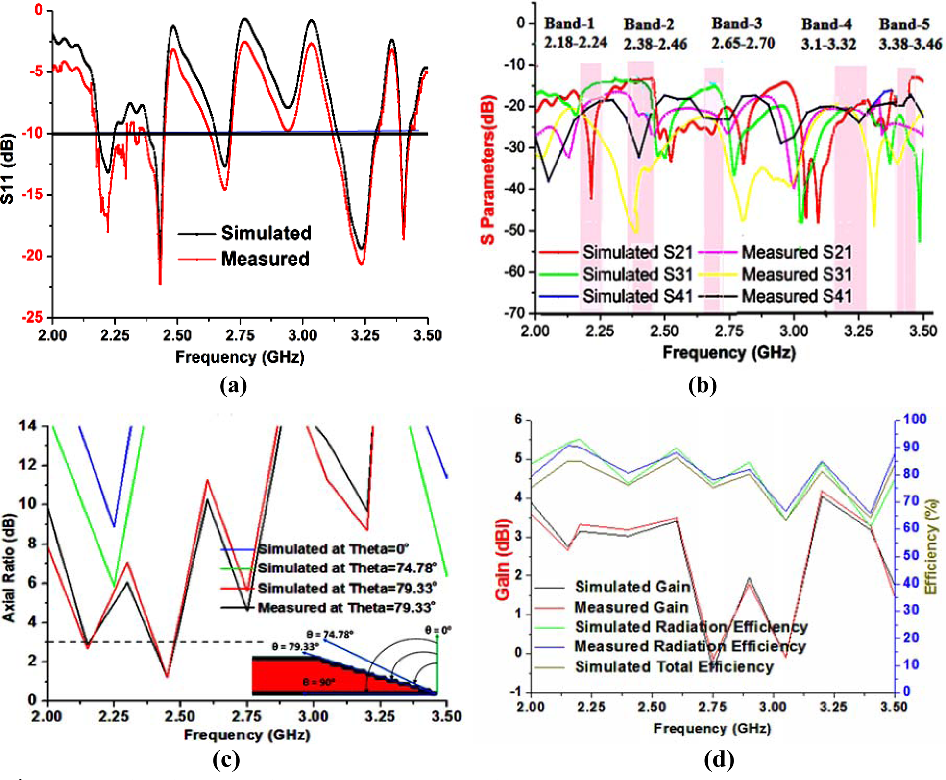
Fig. 4. Simulated and measured results of the proposed antenna in terms of: (a) S 11, (b) S 21, S 31, S 41, (c) axial ratio, and (d) gain, radiation, and total efficiency.
The distribution of the current density (A/m) at 2.2 and 2.4 GHz frequency was rotating clockwise indicated by an arrow when port 1 or 3 has excitation which indicates RH circular polarization of antennas. Similarly, when port 2 or 4 has excitation, the distribution of the current density is rotating anti-clockwise which indicates LH circular polarization of antennas as shown in Fig. 5(a).

Fig. 5. Current density and electric field distribution at: (a) 2.2 and 2.4 GHz frequency for RHCP/LHCP and (b) 2.2, 2.4, 2.6, 3.2, and 3.4 GHz when antenna 1 is energized and remaining antennas are terminated with matched 50 Ω load.
The simulated electric fields (V/m) of an antenna at 2.2, 2.4, 2.6, 3.2, and 3.4 GHz frequencies are represented in Fig. 5(b). Electric-field distribution over the single element provides better insight to understand which portion of the meandering line contributes to the specific bands and it is observed that at a lower frequency (2.2 GHz) electric field covers the entire length of the meandering line. Therefore, the first, second, third, fourth, and fifth resonating frequencies are 2.2, 2.4, 2.6, 3.2, and 3.4 GHz at corresponding meander length of antenna 32.50, 29.73, 27.5, 22.34, and 21.03 mm, respectively.
Three-dimensional radiation patterns are the spatial distribution of the EM field radiated from the transmitting antennas in vertical and horizontal planes as shown in Fig. 6(a), where the maximum radiation intensity of an antenna is observed in ±z-direction at intended frequencies.
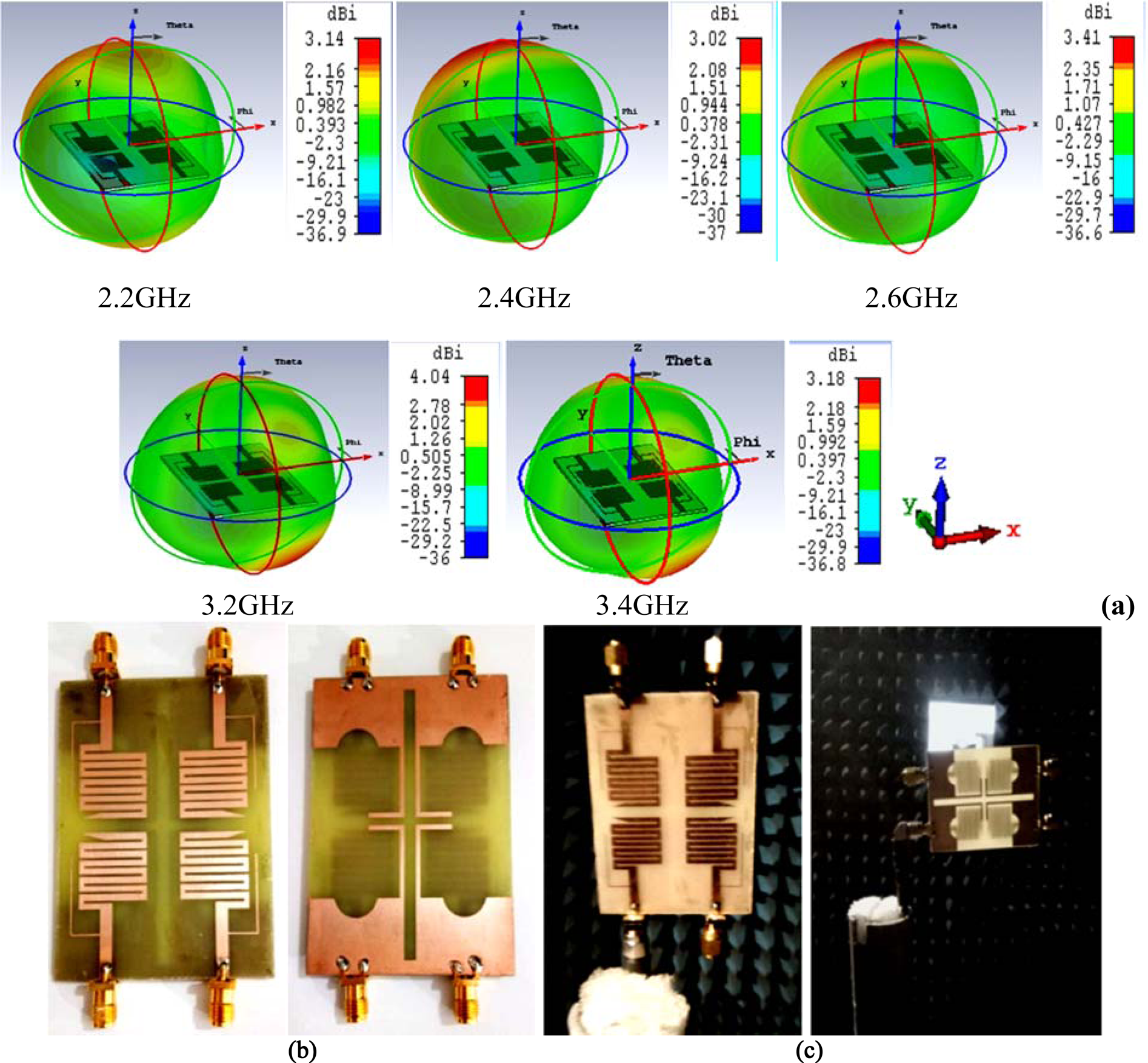
Fig. 6. Three-dimensional radiation pattern of designed MIMO antenna at: (a) 2.2, 2.4, 2.6, 3.2, and 3.4 GHz when antenna-1 is excited only, (b) top and bottom view of a prototype, and (c) antenna under test-AUT for radiation pattern measurement in the anechoic chamber.
This MIMO antenna is fabricated on the FR4 substrate using a double-sided 35 μm copper peel by the double beam photolithography technique as exhibited in Fig. 6(b). The radiation performance of the antenna is also tested in an anechoic chamber associated with vector network analyzer as depicted in Fig. 6(c).
The radiation pattern in E- and H-plane of the MIMO antenna is presented for pentaband applications in Fig. 7. Co- and cross-polarization of the antenna P 1 is simulated and measured when antennas P 2, P 3, and P 4 are terminated with a 50 Ω matched load. Figure 8 represents the measured and simulated radiation patterns of the proposed antenna at frequencies 2.2, 2.4, 2.6, 3.2, and 3.4 GHz, respectively, in E-plane (yz) and H-plane (xz) within the satisfactory range. Here, the authors have considered the RH polarization results at CST Microwave Studio as co-polarization and LH polarization as cross-polarization for E/H-plane radiation patterns, and the same has been considered for measurement data also. It is noted that for the intended pentaband, the patterns are partially omni-directional at Φ = 0o (H-plane) and monopole like at Φ = 90o (E-plane).
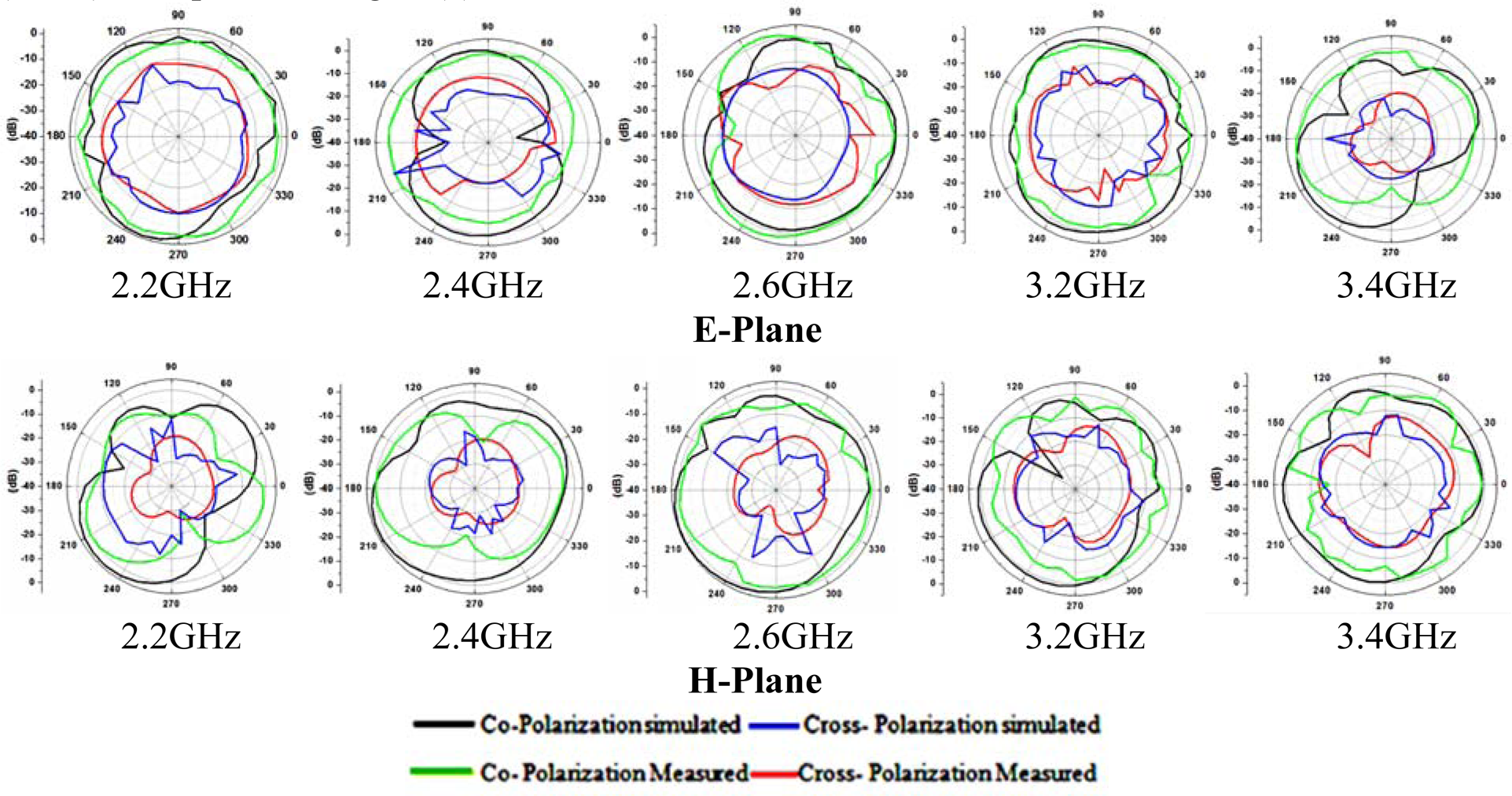
Fig. 7. Simulated and measured two-dimensional radiation patterns at 2.2, 2.4, 2.6, 3.2, and 3.4 GHz for E-plane and H-plane, antenna-1 is energized and the rest of the antennas are terminated by a matched load.

Fig. 8. Specific absorption rate calculation of the designed MIMO antenna near the human head at a distance of 6 mm.
Specific absorption rate
It is the “the power absorbed per unit mass of tissue” and it is a vital component of an antenna when the antenna is used in near-field applications of wireless communication. Radiated EM energy is absorbed by the human body as represented in Fig. 8. Specific absorption rate (SAR) is generally calculated on a small bio-tissue (usually 1 or 10 g) or the entire body [Reference Naser-Moghadasi, Sadeghzadeh, Fakheri, Aribi, Sedghi and Virdee23, Reference Kathuria and Vashisht24]. Furthermore, SAR estimation on the head for the proposed antenna at 2.2, 2.4, 2.6, 3.2, and 3.4 GHz frequencies are represented in Table 2. For the assessment of SAR, the values of the thickness of the brain, bone, and skin are 66, 76, and 79.32 mm, respectively.
Table 2. Simulated SAR at resonant frequencies for the human head at a 6 mm distance

The simulated value of SAR for 1 and 10 g of bio-tissue of the head is less than the permissible limit (i.e. 1.6 W/kg) for the designed MIMO antenna as exhibited in Table 2 corresponding to all parameters scheduled in Table 3. The SAR results are calculated by CST microwave studio without any plastic-jacket or dielectric and cover using the following equation:

where V is the sample volume in m3, σ(r) is the thermal conductivity of the prescribed model in S/m, E rms(r) is total incident rms electric field in V/m, and ρ (r) is the sample density in kg/m3.
Table 3. Parameters of the bio-tissues for skin, bone, and brain used for calculation of SAR of MIMO antenna with constant permeability

MIMO antenna diversity performance
The designed MIMO antenna diversity performance is examined in terms of various parameters like ECC, multiplexing efficiency, channel capacity, CCL, and mean effective gain (MEG).
Envelope correlation coefficient
ECC is one of the diversity parameters to investigate the performance of the MIMO antenna system for wireless applications which shows how many antennas are correlated to each other. It is calculated by equation 2(a) using S-parameters of antennas but this equation is only valid when power is uniformly distributed in the system elements, therefore, currently, the researcher has not preferred this equation for the calculation of ECC. Calculated ECC using S-parameters are shown in Fig. 9(b).


Fig. 9. Measured and simulated results of the proposed MIMO antenna: (a) envelope correlation coefficient from radiated fields, (b) envelope correlation coefficient from S-parameters, and (c) multiplexing efficiency.
As equation 2(a) is not preferred by the researcher, the accurate ECC to be calculated with radiated fields by equation 2(b), and the results are shown in Fig. 9(a).

In equation 2(b), XPR is the power ratio of the cross-polarization of the incident wave. Eθ(Ω) and E Φ(Ω) are the θ and Φ components of an active electric field where Ω is the beam solid angle. Pθ and P Φ are the θ and Φ components of the angular power density of incoming waves. The unity cross-polarization is achieved when Pθ = P Φ = 1/4π. Polarized signal active gain patterns are denoted by Gθ and G Φ for any propagation environment. Gθi = Ei × Ei*, Gθj = Ej × Ej*, G Φi = Ei × Ei*, G Φj = Ej × Ej*are the relations between active gain patterns and electric field components. Using these relations, equation 2(b) becomes equation 2(c) [Reference Loyka28].

The electric field of the i th and the j th element is denoted by Ei and Ej. Ideally, ECC has zero value for an un-correlated MIMO antenna system but the practically acceptable value for the MIMO system is less than or equal to 0.5. The calculated and measured values of ECC between two antenna elements of a designed four-element antenna by S-parameters and radiated fields in all prescribed bands are observed <0.1 as exhibited in Figs 9(a) and 9(b), respectively. Hence, this MIMO antenna shows less correlation between the two antennas in the MIMO system and gets excellent diversity performance.
Diversity gain
Diversity gain (DG) is also an important parameter of the MIMO antenna system. The DG is an increment of signal-to-interference ratio due to some diversity scheme or to reduce the transmission power by using this scheme without compromising the performance of an antenna. Diversity gain is depending on cross-correlation between the transmitted signals from the adjacent antennas and the relative mean power level. The DG of the MIMO antenna is calculated by $\;DG = 10 \times \sqrt {( {1-ECC^2} ) }$ . For the effective operation of the MIMO antenna system, the value of DG should be close to 10 dB. The calculated values of DG in all intended bands are more than 9.8 dB.
Multiplexing efficiency
The main feature of multiplexing efficiency is to show the correlation and efficiency imbalance between MIMO antennas used in a wireless system. The ratio of radiated power of an i th antenna and reference (isotropic) antenna is multiplexing efficiency (ηMUX). The ηMUX of the MIMO antenna is calculated by $ME = \left[{\left({\prod\limits_{i = 1}^k {\eta_i} } \right)\bullet \det ( {\psi}^{\kern1ptp} ) } \right]^{1/k}$ , where ηi stands for the total efficiency of the i th antenna, ψ p is the normalized antenna correlation matrix [Reference Li, Xu, Ban and Yu29].
Hence, the values of total and multiplexing efficiency are more or less identical (70%) and the value of efficiency goes down at the unintended bands as shown in Fig. 9(c).
Channel capacity
Channel capacity of the MIMO antenna is investigated to know the data rate which is dependent on bandwidth and signal-to-noise ratio (SNR). The channel capacity of the four-element pentaband MIMO antenna is verified with the average channel capacity of the standard MIMO system which is calculated by equation (3). The minimum and maximum threshold levels of channel capacity of the four-element antenna are varying between 14.85 and 22.68 bps/Hz at 20 dB SNR in a uniform environment as shown in Fig. 10(a).

Channel capacity directly depends upon the number of antenna elements and the correlation between them. But the CCL also increases with the increase of the number of antennas in the system for fixed S/N value. Therefore, CCL reduces the throughput or channel capacity of the proposed MIMO antenna as shown in Fig. 10(c), where k is the number of antennas used in a MIMO system for transmitting or receiving EM signals. An identity matrix is denoted by [I] and SNR is the ratio of signals of device terminals and distribution channels in a Rayleigh fading environment. The value of SNR for the calculation of channel capacity is 20 dB. H and H* are the channel fading matrix and Hermitian transpose of H, respectively. For an ideal MIMO antenna, the correlation between them is negligible so [H] [H*] = [I]. Maximum channel capacity of the four-element MIMO antenna system is 26.63 bps/Hz but the permissible limit is 65–70% of its maximum value (26.63 × 0.65 = 17.30 bps/Hz) [Reference Saxena, Jain and Awasthi26, Reference Loyka28]. The main factor behind the use of the MIMO antenna is to get an enhanced channel capacity at an appropriate level. However, the channel capacity of a wireless communication system is also dependent on the number of antenna elements used in the system and the correlation between antenna elements. This means channel capacity will be increased with an increase of un-correlation between antenna elements.

Fig. 10. The proposed four-element antenna: (a) calculated average channel capacity, (b) simulated and measured results of channel capacity loss, and (c) simulated channel capacity versus SNR.
Channel capacity loss
CCL is also related to the amount of correlation between antenna elements used in the MIMO system and it is calculated by using equations (4)–(6) [Reference Saxena, Jain and Awasthi26, Reference Saxena, Jain and Awasthi27, Reference Biswal and Das30]. The values of simulated and measured CCL are below the prescribed (0.5 bps/Hz) limit for intended pentabands as shown in Fig. 10(b). However, the CCL of the MIMO system is linearly increased when we increase the number of antenna elements. If we increase the antenna elements then the correlation factor between antenna elements increases which increases the CCL. Therefore, the diversity performance of the proposed antenna will be affected by increasing the number of antenna elements. CCL of four-element antenna is calculated as follows:

where, $\psi ^p = \left[{\matrix{ {\rho_{11}} & {\rho_{12}} & {\rho_{13}} & {\rho_{14}} \cr {\rho_{21}} & {\rho_{22}} & {\rho_{23}} & {\rho_{24}} \cr {\rho_{31}} & {\rho_{32}} & {\rho_{33}} & {\rho_{34}} \cr {\rho_{41}} & {\rho_{42}} & {\rho_{43}} & {\rho_{44}} \cr } } \right]$


where i, j, and n = 1, 2, 3, 4.
Figure 10(b) shows the CCLs and it is <0.35 bps/Hz over the intended bands, which indicate a good diversity performance of the proposed pentaband MIMO antenna.
Total active reflection coefficient
In a four-port antenna system, adjacent antenna elements interrupt each other when they are excited at the same instant. This type of interruption affects the antenna performance parameters like overall gain, efficiency, and bandwidth of multiband. Therefore, the actual performance of the MIMO antenna system will not be extracted by scattering parameters only, but also by the total active reflection coefficient (TARC). It is defined as the square root of the sum of all incident powers at the ports minus radiation power, divided by the sum of all incident powers at the ports. The TARC of the proposed four-element MIMO system is calculated by equation (7)–(9) [Reference Saxena, Jain and Awasthi26, Reference Saxena, Jain and Awasthi27, Reference Biswal and Das30].

where ai and bi are an incident and reflected EM wave, respectively, and n denotes the number of antenna elements used in the MIMO system at transmitting or receiving ends.

where [S], [a], and [b] are scattering, incident, and reflected matrix of four-port multiband MIMO antenna, respectively.

In general, TARC should be less than −10 dB for better MIMO antenna performance, and TARC of the fabricated and simulated proposed MIMO antenna is less than −40 dB in the intended bands. Hence, the designed antenna is depicted as a good diversity criterion for a MIMO wireless communication system.
Mean effective gain
MEG is an important parameter to investigate the diversity performance of the MIMO antenna and it gives information about how much mean power is received when input power is fed along the same route. MEG of the proposed pentaband MIMO antenna can be calculated by equation (10) [Reference Saxena, Jain and Awasthi26, Reference Saxena, Jain and Awasthi27, Reference Biswal and Das30].

where power gain [Gθi (Ω), G Φi (Ω),] and density [P Φ (Ω)] are the functions of the beam solid angle of the incident wave. The acceptable MEG of i th and j th antenna elements is ≤ −3 dB.
The MEG is calculated for the proposed antenna based on three propagation models where XPR has different values as 0dB, 1.0dB, and 6.0 dB for isotropic, outdoor, and indoor with different mediums like isotropic, Gaussian, and Laplacian as shown in Table 4 and Fig. 11. The MEG of the proposed antenna falls within the permissible limit (≤ ± 3 dB) for all bands. Hence, the proposed antenna has high-quality channel performance which applies to wireless communication.

Fig. 11. Simulated results of mean effective gain of the proposed antenna in isotropic, Laplacian, and Gaussian medium for indoor and outdoor values.
Table 4. Simulated MEG results of pentaband MIMO antenna at various XPR and frequencies

The various power levels in terms of power loss, power accepted, power outgoing to all ports and power radiated by the proposed antenna have been examined for SAR calculation as shown in Fig. 12. Here, 0.5 W stimulated power is used for the calculation of all powers and diversity parameters. In the proposed antenna, most of the power is radiated because this antenna has minimum power loss in intended bands. Power accepted is almost equal to stimulated power except unintended bands due to poor return loss means power returns back to the same ports. The radiated power is less than stimulated power because dielectric, conductor, and surface wave losses are associated with the proposed antenna. Powers going to all ports highly interfere at other than the intended bands because at unintended bands most of the power is correlated between ports and power at the ports will not reach the antenna for radiation. Table 5 shows the comparison of the performance of the pentaband MIMO antenna with existing multiband MIMO antennas at diverse parameters. So, it is observed from Table 5 that the proposed antenna is having good radiation efficiency, ECC, and CCL including dual-band circular polarization characteristics. A lower value of ECC and CCL provides better channel capacity and less outage probability and circular polarization in two-band is applicable to immune the noise, produced due to Faraday rotation when the radiated field passes through the ionosphere layer. Hence, the proposed MIMO antenna provides better performance in comparison with the existing references.

Fig. 12. Power levels of the designed MIMO antenna in various states as power loss, power stimulated, power accepted, and power radiated, power absorbed, and power outgoing.
Table 5. Comparison of the performance of pentaband MIMO antenna with existing multiband MIMO antennas at diverse parameters

[P], Proposed.
Conclusion
A four-element MIMO antenna has been proposed for pentaband applications as mobile satellite services (MSS), IoT, ISM, broadband radio services, educational broadband services, WLAN, and WiMAX including dual-band circular polarization. All the simulated results of the antenna had confirmed with measured results in the intended pentaband. The antenna has achieved 3.58 dBi peak gain with almost stable omnidirectional radiation patterns with acceptable diversity performance like ECC, TARC, CCL, DG have values 0.005, −40 dB, 0.35 bps/Hz, and 9.9 dB, respectively, as shown in Table 5. The SAR performance of the proposed four ports MIMO antenna is calculated, it is also under the permissible limits for 1 and 10 g of bio-tissue of the head. The diversity and antenna performance of the proposed antenna is excellent in all respect for wireless communications; this means the antenna is useful in various portable wireless applications with an average channel capacity of 19.68 bps/Hz.
 Gaurav Saxena received his B.Tech degree in Electronics and Communication Engineering, from Uttar Pradesh Technical University Lucknow, India, in 2007, M.Tech degree in Microwave Electronics, from University of Delhi, South Campus, Delhi, India, in 2012, and completed Ph.D. from Delhi Technological University, Delhi, India in 2020. He also received a meritorious scholarship from July 2010 to July 2012 given by the University of Delhi. From December 2011 to May 2012 he worked as an internship trainee at CSIR, NPL Delhi where he established tractability of the VNA and received an appreciation certificate. Currently, he is working as an Associate Professor at Galgotia College of Engineering and Technology, Greater Noida, Uttar Pradesh. His recent research interest includes modelling of passive microwave components; microwave antenna for 5 G and wireless applications, meta-material absorber, MIMO receiver/transmitter, microwave components like filters power divider/combiner, THz MIMO antenna, absorber, and so on.
 Yogendra Kumar Awasthi received the B.Sc (Electronics) degree from Dr. BRA University, Agra, India in 1999, the M.Sc. (Electronics & Computational Physics) degree from Institute of Basic Science, Dr. BRA University, Agra, India in 2001, and Ph.D. (RF & Microwave Electronics) from Delhi University, Delhi, in 2012. He was co-operative faculty at the University of Delhi, New Delhi and he was also guest faculty at Central Electronics Engineering Research Institute, Pilani, and Rajasthan, India in 2006–2012. He is currently working as a Professor with the Department of Electronics and Communication Engineering, Manav Rachna International Institute of Research and Studies University, Faridabad, India. He has published more than 80 articles in peer-reviewed journals and conferences and he has also filed/published seven patents and published one book's chapter. His recent research interest includes modeling of high-frequency passive microwave components, microwave antenna for LTE & 5 G applications, meta-material absorber, sensor & cloaking, study of transient, RF power transfer & energy harvesting, MIMO receiver system, electrical power system, and so on.
He is an Editor-in-Chief in the renowned “Journal of Sciences and Technology” and working as a reviewer of several refereed journals such as IEEE Antennas and Propagation Magazine, IET Microwaves, Antennas, Propagation, IET Electronic Letter, IEEE Access, IEEE Transactions on Antennas & Propagation, AEUE International Journal of Electronics and Communication, Elsevier, Journal of Electromagnetic Waves and Applications (JEMWA), Taylor & Francis, International Journal of Electronics, Taylor & Francis and Applied Computational Electromagnetic Society, ACES.
 Priyanka Jain received her B.E. degree in Electronics and Communication Engineering, M.Tech degree in Microwave Electronics, from the University of Delhi, South Campus, Delhi, India, and Ph.D. from GGSIPU Delhi, India. Currently, she is working as an Associate Professor, Delhi Technological University, Delhi, India. She has published various articles in peer-reviewed journals and conferences. Her recent research interest includes modelling of passive microwave components, microwave antenna for 5 G applications, meta-material absorber, MIMO receiver/transmitter system, and so on.


