Introduction
The need for flexible wireless devices is growing fast due to their wide area of applications in our daily life including wearable and implantable electronics [Reference Hall and Hao1]. A new challenge has been identified in antenna design for wireless systems which is that to achieve a design capable of keeping its radiation features under different bending conditions. In response, several design approaches of compact/flexible antennas, operating within numerous frequency bands, were reported in [Reference Saeed, Balanis and Birtcher2–Reference Deng, Liu, Zhang and Tentzeris6].
Ultra wideband (UWB) technology has offered great promise to satisfy high capacity growing applications [Reference Oppermann, Hämäläinen and Iinatti7]. One of frequency allocations assigned to UWB services utilizes the spectrum from 3.1 to 10.6 GHz [8]. This large bandwidth and the potential for low processing power with low implementation cost present an exclusive opportunity for UWB to become a widely adopted radio solution for Internet of Things (IoT) flexible wireless indoor applications [Reference Greengard9].
Along with more requirements in wireless wide band communication, it is becoming more important to improve the 3 dB axial ratio bandwidth (ARBW) of circularly polarized (CP) antennas. Mainly spiral antennas are used to achieve broadband CP property because of their inherited broadband characteristics on impedance and ARBW. Yet, they usually occupy large space and need a complex feed network. Various types of non-flexible CP patch antennas have been proposed, recently [Reference George Thomas and Praveen10–Reference Ahdi Rezaeieh, Abbosh and Antoniades21], a summary is listed in Table 1. In the same table, another comparison is presented between some published flexible CP antennas [Reference Fujita, Kanemoto, Yoshitomi, Yoshida and Kanaya22–Reference Ehteshami, Sathi and Ehteshami26].
Table 1. Comparison between published single fed CP wideband antennas ([Reference George Thomas and Praveen10–Reference Ahdi Rezaeieh, Abbosh and Antoniades21]) and CP flexible antennas ([Reference Fujita, Kanemoto, Yoshitomi, Yoshida and Kanaya22–Reference Ehteshami, Sathi and Ehteshami26])

As the UWB pulse endures very short time (<2 ns), utilizing that huge frequency range, it is more susceptible to be distorted through the transmitting/receiving system. Therefore, time domain investigation has become a necessary study for all wideband antennas as in [Reference Quintero, Zürcher and Skrivervik27–Reference Zahran, Abdalla and Budimir31].
In this work, a single fed wideband flexible CP antenna with new rotated elliptical ground (REP) is proposed. The antenna structure and the basic wideband design specifications are presented in “Antenna structure and design results” section. The antenna has three main features: flexible, CP, and efficient impulse response (IR) over wideband of operation. These features are presented throughout this work: (1) investigation of CP radiation properties with design verifications and parametric analysis is discussed in “Rotated elliptical ground effect on circular polarization” section. (2) Flexibility and bending functionality of the CP antenna are emphasized in “Bent antenna results” section. (3) The time domain functionality for the CP bent antenna is presented in “Time domain analysis” section.
Antenna structure and design results
Antenna structure
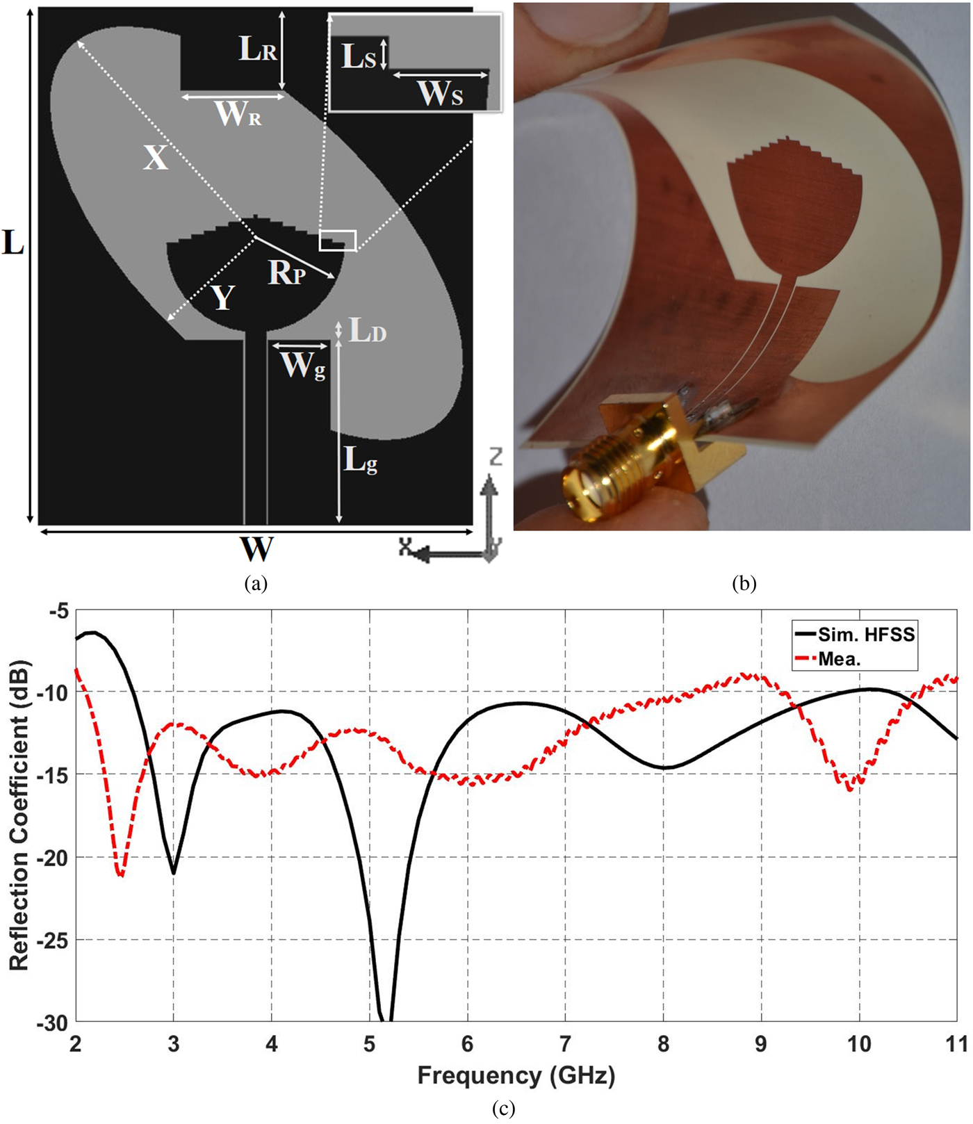
The used substrate for the proposed antenna was selected so that the antenna can perform effectively under extreme bending. Hence, Rogers Ultralam 3850 was selected as it consists of Liquid Crystalline Polymer (LCP) substrate with a thickness of 100 µm, loss tangent of 0.0025, dielectric constant of 3.14, and copper cladding with a thickness of 18 µm. Proposed antenna labeled layout geometry is shown in Fig. 1(a). The slot antenna is excited by a 2 mm-wide 50 Ω CPW transmission line. The main radiator is a pyramidal staircase on top of a semi-circle, it is located in the middle of an elliptical etched ground that surrounds the patch from all angles, the size of the antenna is 50 mm × 42 mm. With only one feeding port, CP radiation is generated by the assistance of 45° REG.

Fig. 1. Proposed CP flexible antenna. (a) Labeled geometry layout in mm (L = 50, W = 42, L g = 17.9, W g = 6, L R = 8, W R = 9.96, R P = 8.6, L S = 1.2, W S = 0.4, L D = 0.8, X = 25.5, Y = 12.24), (b) photograph of the fabricated bent antenna prototype, (c) simulated and measured reflection coefficient.
The fabrication of the antenna was performed using photolithography process followed by sensitive chemical etching treatment. The fabricated bent antenna is photographed in Fig. 1(b). It is worth to comment that in order to conduct measurements, a SMA connector was adhered using a special type of conductive epoxy in order to ease connector placement at room temperature without any thermal intrusion.
The electromagnetic full-wave simulation of the CP antenna was executed using commercial ANSYS electronic desktop software. The reflection coefficient (S 11) of the fabricated antenna was measured using FieldFox N9918A Vector Network Analyzer. The simulated and measured reflection coefficients are illustrated in Fig. 1(c), where a good agreement, in terms of curve pattern, is confirmed. The simulated S 11 is below −10 dB from 2.6 to 10 GHz with resonance frequencies at 3 and 5.2 GHz. However, a noticeable shift in measured S 11 curve toward lower frequencies exists as a result of imperfect fabrication.
Far-field radiation properties
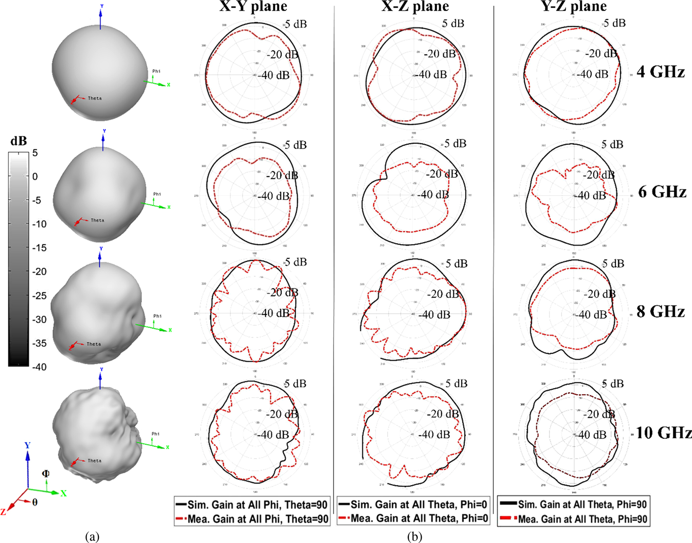
Within UWB allocated spectrum, the frequencies 4, 6, 8, and 10 GHz have been selected to investigate far-field results. The simulated three-dimensional polar gain patterns in dB at the selected frequencies are illustrated in Fig. 2(a). It is observed that a semi-omnidirectional radiation pattern at lower frequencies and a deformation is observed as frequency increases. These results confirm the suitability of the antenna for UWB indoor applications. It is noticeable that the maximum gain over most of the band is located at θ = 70° and Φ = 90° (this angle will be identified as boresight angle). The antenna radiation pattern measurement has been done using SATIMO Starlab anechoic chamber. A comparison between measured and simulated gain patterns in the principal plans is illustrated in Fig. 2(b). Both simulated and measured results show consistency in magnitude. The differences between them are due to non-avoidable manufacturing/measurement-related errors. The simulated antenna gain is plotted in Fig. 3(a), where it can be noticed that the average gain for lower frequencies (up to 9 GHz) is approximately 3 dB and it outreaches 6 dB at 10 GHz.
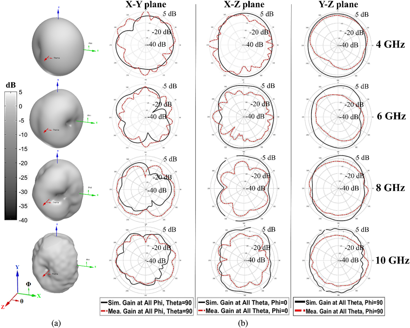
Fig. 2. Total gain in dB of the proposed antenna. (a) Simulated 3D polar gain, (b) simulated and measured 2D gain radiation pattern.
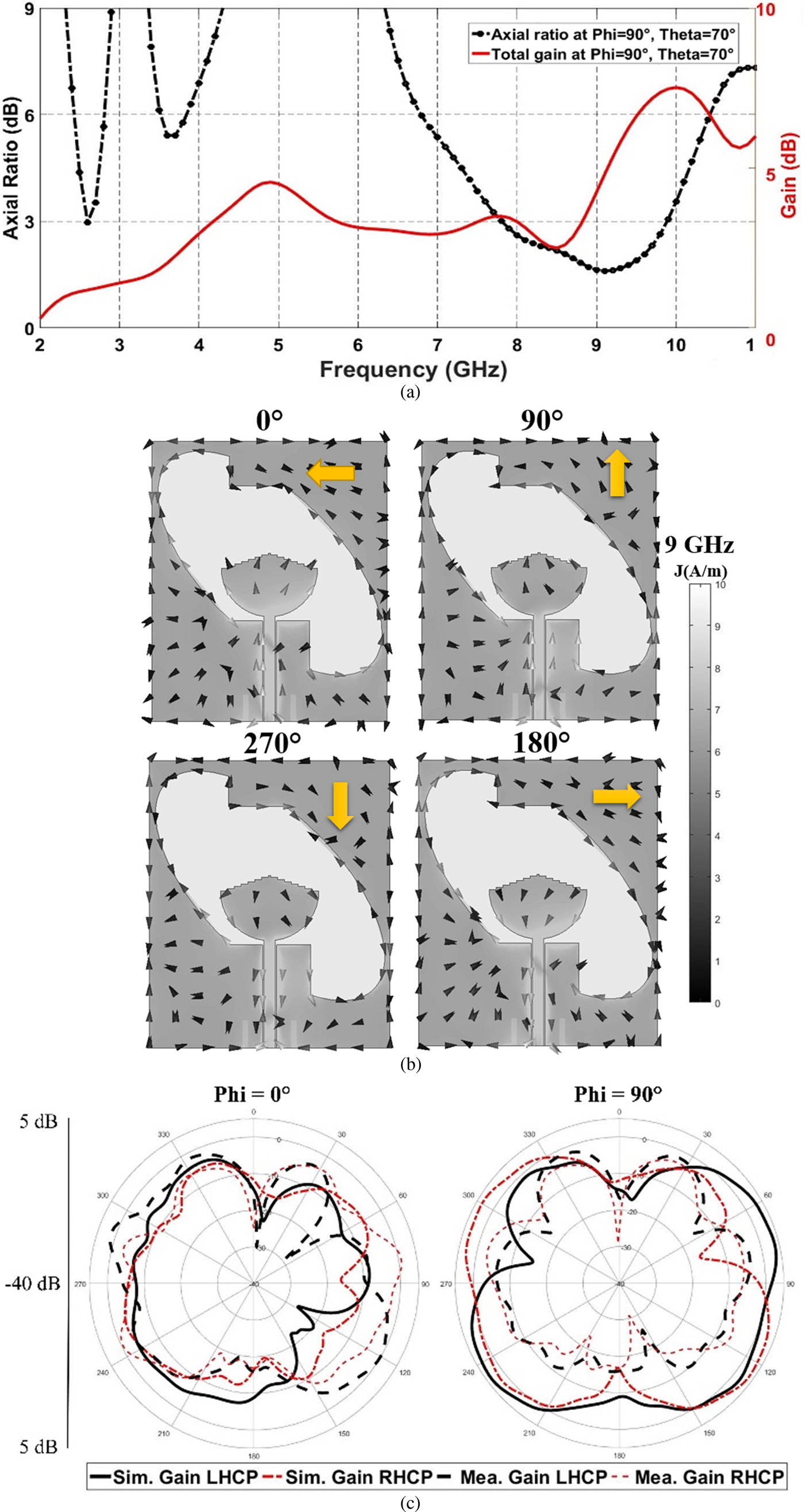
Fig. 3. Flexible CP antenna performance. (a) Simulated boresight total gain (right axis) and axial ratio (left axis), (b) the simulated surface current distribution vector/magnitude for different phases (ωt) at 9 GHz, (c) the simulated and measured radiation pattern of gain LHCP and RHCP for all θ where Φ = 0° and 90° (XZ and YZ planes) at 9 GHz.
Rotated elliptical ground effect on circular polarization
In this section, the CP properties and characteristics of the proposed antenna are emphasized. The simulated boresight axial ratio against frequency is plotted in Fig. 3(a). As it can be observed, the 3 dB axial ratio is intersecting with UWB allocated BW from 7.9 to 9.9 GHz range. In order to investigate CP generation, the distributions of surface current vector at different phases (ωt) of 9 GHz (selected between 7.9 and 9.9 GHz) are illustrated in Fig. 3(b). It is observed that the current vector circulates in clock wise direction as phase varies in the whole structure except for two areas: the radiator's right half and the REG's bottom right corner, where the rotation is in counter clock wise direction. The net result shows that clock wise rotation of current is more dominant than counter clock wise, this indicates a left-hand circular polarization (LHCP) is generated in +Y direction and right-hand circular polarization (RHCP) is generated in –Y direction. This conclusion can also be confirmed by investigating the simulated 2D radiation pattern of LHCP and RHCP gain in dB at Φ = 0 and 90° for all θ at 9 GHz as represented in Fig. 3(c). The figure confirms that at Φ = 90°, LHCP is dominant from θ = 0 to 90° direction and RHCP is dominant in θ = −90 to 0° direction at 9 GHz.
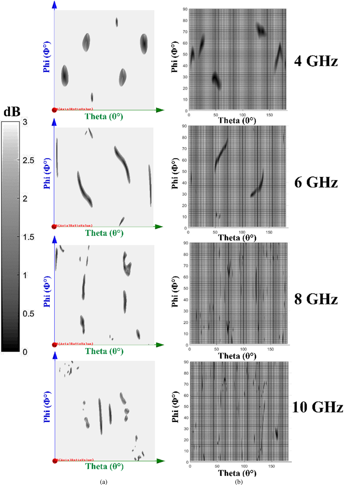
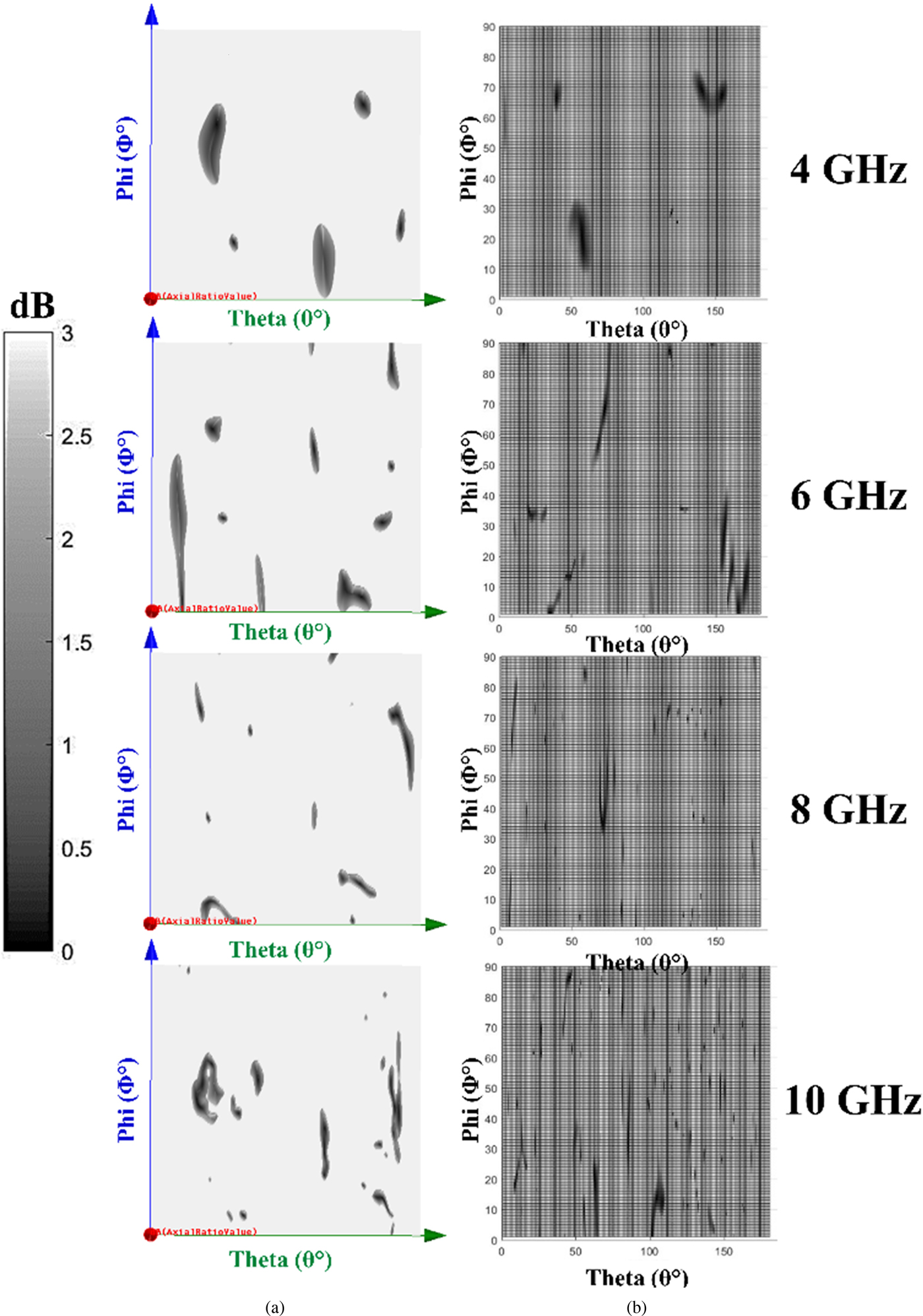
To facilitate polarization investigation, Fig. 4, illustrates the simulated and measured rectangular axial ratio against Φ and θ (maximized to 3 dB: useful in indicating the exact angles at which axial ratio is lower than 3 dB). It can be observed that not only CP is generated within 7.9–9.9 GHz range, but also CP is achieved over the whole spectrum of operation indicated at various angles other than the boresight due to the presence of the REG. This feature is suitable for IoT's indoor (line of site independent multi-reflections environment) wearable applications. To achieve an optimum antenna design and investigate the effect of the REP on the antenna's matching, gain, and AR, before achieving the final design. Series of simulation-based parametrical studies of the elliptical ground were conducted.

Fig. 4. Three-dimensional rectangular axial ratio in dB at different frequencies. (a) Simulation, (b) measurement.
Ground ellipse eccentricity effect
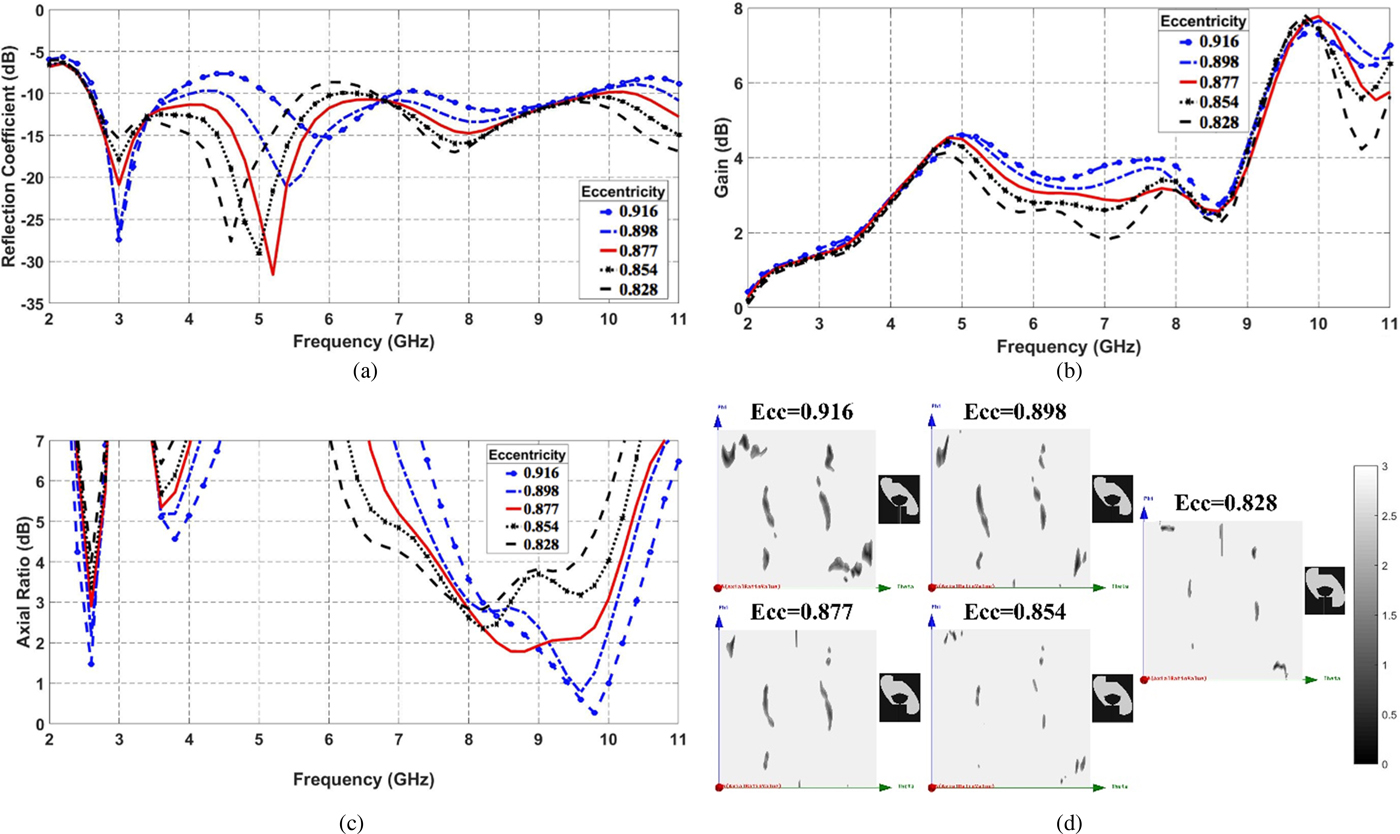
The ground ellipse was designed based on the eccentricity (Ecc) equation in (1), where X and Y are the dimensions labeled in Fig. 1(a). As shown in Fig. 5(a), a shift in antenna's reflection coefficient curve toward high frequency as eccentricity increases. Also, S 11 with higher than −10 dB is observed at the highest eccentricity. Next step is to investigate the far-field gain (boresight angle) as presented in Fig. 5(b), it can be claimed that gain is identical for all cases except for 4.5–8.5 GHz band in which it tends to increase to 4 dB as eccentricity increases. Finally, the axial ratio against frequency is plotted in Fig. 5(c), and the 3D rectangular axial ratio at 9 GHz is illustrated in Fig. 5(d). Both figures demonstrate that better results for AR (<3 dB) are achieved as eccentricity increases. As a result of trade-off between antenna matching, gain, and AR, a final design is achieved that has eccentricity 0.877 calculated by substituting X and Y from Fig. 1(a), in (1).
 $$Ecc = \sqrt {\displaystyle{{X^2-Y^2} \over {X^2}}}. $$
Fig. 5. Comparison between simulated designs with different values of elliptical ground eccentricity in terms of (a) reflection coefficient, (b) far-field boresight gain, (c) far-field boresight axial ratio, (d) 3D rectangular axial ratio in dB at 9 GHz.
Ground ellipse rotation angle effect
The ground ellipse rotation angle is identical to the azimuth angle (θ). In this parametrical analysis, different values were assigned to θ. In Fig. 6(a), stability in reflection coefficient at different values of θ is obvious. Figure 6(b) represents a tremendous variation in antenna's boresight gain, where it can be observed that at low frequencies, there is 1.5 dB difference for both 35 and 55° designs when compared with 45° design, and for higher frequencies, both of these structures outreach 7.5 dB of boresight gain. On the other hand, the −45° structure has almost 0.8 dB shift in gain when compared with −45° structure in the favor of the 45° structure.
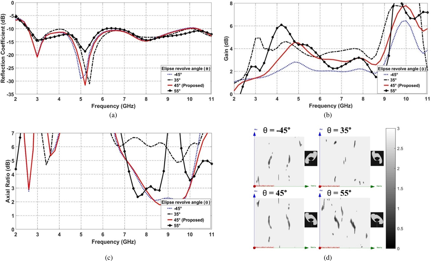
Fig. 6. Comparison between simulated designs with different values of ground ellipse rotation angle in terms of (a) reflection coefficient, (b) far-field boresight gain, (c) far-field boresight axial ratio, (d) 3D rectangular axial ratio in dB at 9 GHz.
Figure 6(c) shows the far-field boresight axial ratio for different values of rotation angle (θ). It can be observed that AR at θ = 35° is never lower than 3 dB, but on the other hand, 3 dB axial ratio is achieved for θ = 55° for a small band. Finally, Fig. 6(d) indicates that the highest number of <3 dB axial ratio angles occur at θ = 55° compared with the other cases. By trade off, the final θ value that was selected for the proposed antenna is 45° as it achieves reasonable axial ratio values over wide angles and the highest gain compared with 55 and 35° cases.
Bent antenna results
In this section, a study of the antenna's bending feature is presented. The simulation results are obtained when the antenna is bent over an imaginary cylinder having radius denoted by R x, where R x is set to be 25 mm as shown in Fig. 7(a). As illustrated in Fig. 7(b), the actual antenna is bent and fixed upon a semi-cylinder made of non-absorptive Styrofoam material (ε r = 1.03). The impact of bending the proposed antenna is investigated by inspecting far-field gain and axial ratio.
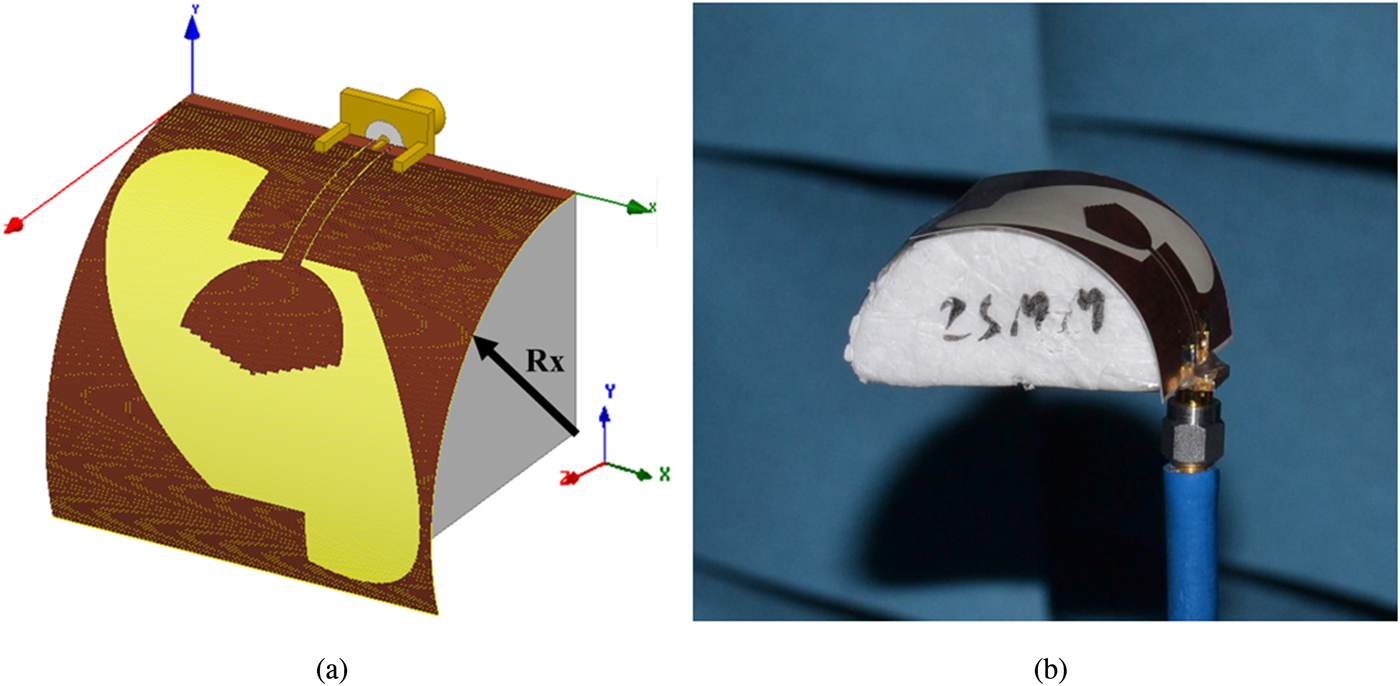
Fig. 7. Bent antenna setup. (a) Simulation: bent over an imaginary semi-cylinder with radius R x = 25 mm, (b) prototype: measurement inside anechoic chamber bent over styrofoam semi-cylinder with radius 25 mm.
Figure 8(a) demonstrates the simulated 3D gain pattern produced from bent antenna setup. As it can be observed that boresight angle of maximum gain shifted to coincide with Z-axis, which is almost 70° shift in elevation indicating that there is a direct relation between the boresight angle and the value of R x, noting that this level of bending is not critical enough to damage or deform the substrate. The measured output is included within the comparison presented in Fig. 8(b). As presented, the measured and simulated gain results agree in magnitude with some variations in pattern shape in some cases specially, at high frequencies but the overall results are ensuring that the antenna can still operate efficiently while being bent.

Fig. 8. Total gain in dB of the bent antenna setup. (a) Simulated 3D polar gain, (b) simulated and measured 2D gain radiation pattern.
As an impact of bending the antenna, the surface current is redistributed over the structure leading to reformation of the angles where 3 dB axial ratio is produced. As shown in Fig. 9, both the simulated and measured axial ratio rectangular plots indicate that the angles at which CP is produced were redistributed. This opens the door for mechanical variation detection applications that require very narrow response time in environments where only wireless signals can be detected.

Fig. 9. Three-dimensional rectangular axial ratio in dB of the bent configuration at different frequencies. (a) Simulation, (b) measurement.
Time domain analysis
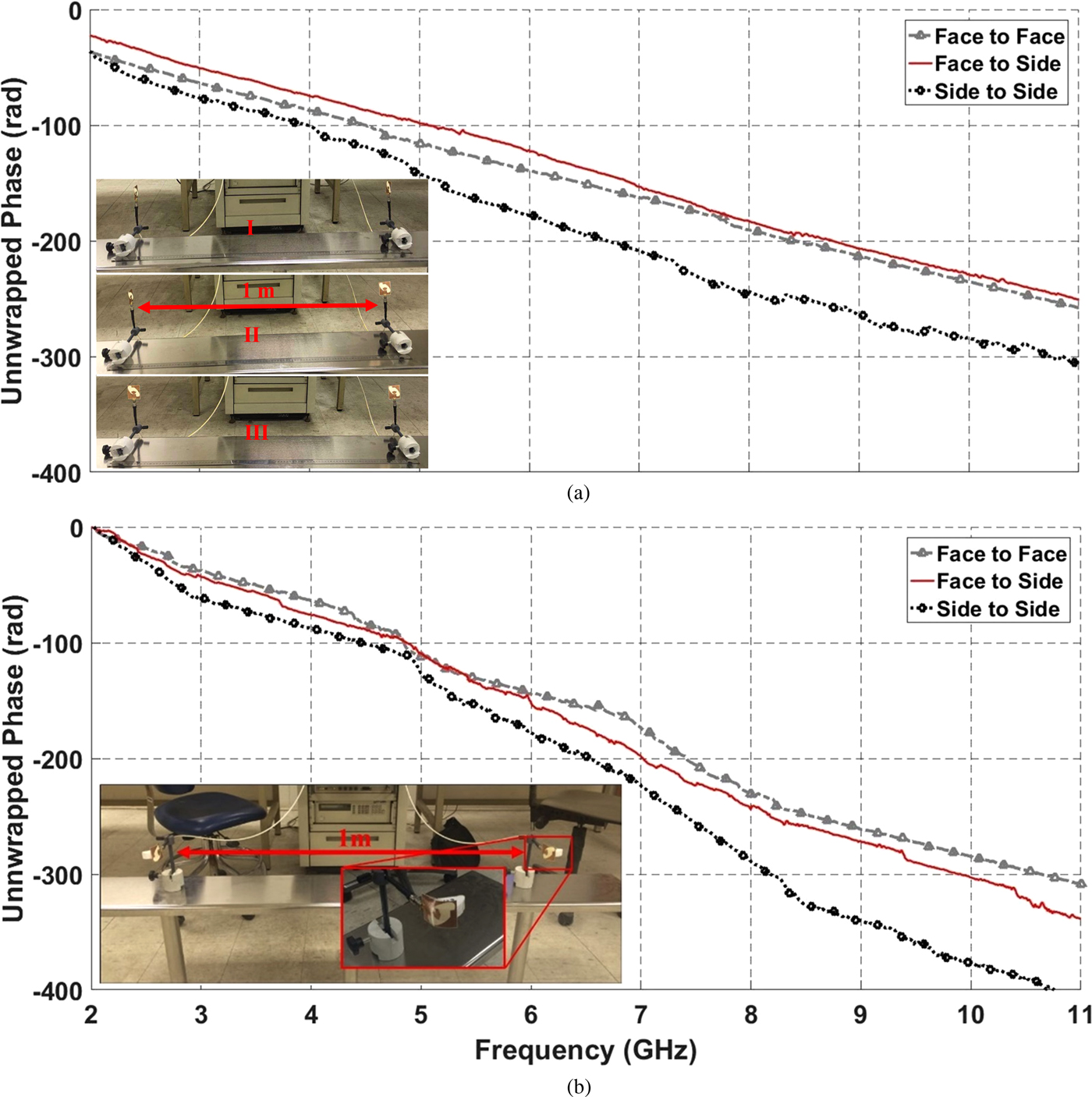
The IR in time domain for straight and bent antenna setup scenarios are presented in this section. The transmission coefficient S 21 between two identical CP antennas connected to VNA ports, separated by 1 m (>far-field barrier) is extracted for three different configuration setups of both antennas. These configurations are face-to-face, face-to-side, and side-to-side as depicted in the subfigures of Figs 10(a) and 10(b). These setups were intentionally constructed in such multi-reflections environment in order to imitate a real operational situation in which an indoor wearable antenna would operate in, as adopted in [Reference Nikolaou, Ponchak, Papapolymerou and Tentzeris4, Reference Gao, Hu and Zhang29]. The system's IR is calculated using (2) as in [Reference Abdelraheem and Abdalla28–Reference Zahran, Abdalla and Budimir31], where the input signal is a first-order Rayleigh pulse with characteristic time (a = 50 ps).
 $$IR(t) = IFFT\lpar {FFT\lpar {{\rm sin}\lpar {2\pi f_\circ t} \rpar .e^{- t-1^2/a}} \rpar .\; S_{21}\lpar \omega \rpar } \rpar .$$
Fig. 10. Measured S 21 for phase for different antenna setups ((I) face-to-face, (II) face-to-side, (III) side-to-side). (a) Straight antennas setup, (b) bent face-to-face antennas setup.
The measured phase of the system's transfer function (transmission coefficient or S 21) is depicted in Fig. (10), for both straight and bent antenna setup scenarios. As quoted from [Reference Abdelraheem and Abdalla28]: “The phase response of the system is to be investigated, as its nonlinearity is greatly responsible for the distortion of the pulse in the time domain”. Figures 10(a) and 10(b) represent linearity in unwrapped phase for both straight and bent scenarios. As observed in Fig. 10(a), face-to-face and face-to-side scenarios coincide in phase, while side-to-side setup's phase shows minor increase in its slope for frequencies higher than 5 GHz. This is due to the deformation in gain at side views (X-axis) for these frequencies as depicted in Fig. 2(a). Figure 10(b) shows agreement in phase for all three setup scenarios at frequencies <7 GHz where afterwards side-to-side setup curve starts to deviate with higher slope for the same reason stated in the previous case of straight antenna setup scenarios (revise Fig. 8(a)). The linearity in measured S 21’s phases indicates that system offers a good IM.
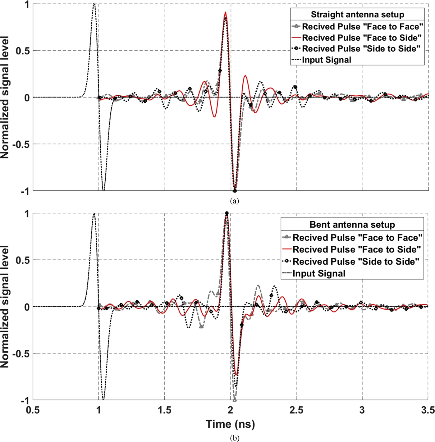
By substituting the previously measured transmission coefficients (S 21) and the Rayleigh input signal in (2), an R x signal for each setup scenario can be obtained. Figures 11(a) and 11(b) represent the input signal in addition to the calculated received pulses for all three setup scenarios of straight and bent antennas, respectively. Note that the received pulses are delayed by 1 ns in order to illustrate any distortions. It is observed that received signals are highly correlated to the input signal except for minor distorted ripples and side ringing patterns, these ripples are <20% in signal level compared with the main pulse for all measured cases. Table 2 indicates excellent matching in cross-correlation between input signal and all received pulses for both straight and bent antenna scenarios.

Fig. 11. Normalized input and received (delayed by 1 ns) pulses. (a) Straight antenna setup, (b) bent antenna setup.
Table 2. Received and input pulses cross-correlation

Conclusion
A novel wideband flexible single fed slot antenna is proposed. It is fabricated using flexible LCP material, has a compact volume of 50 mm × 42 mm × 0.1 mm and 100% impedance matching with FCC's UWB spectrum. The average gain is 4 dB at boresight and the produced pattern is semi-omnidirectional which makes it suitable for wearable indoor wideband applications. A new 45° REP structure was introduced and investigated for generating CP with 3 dB ARBW from 7.9 to 9.9 GHz at boresight where LHCP is dominant. Parametrical analysis targeting the REG structure resulted with design eccentricity of 0.877 and rotation angle of +45°. CP production is confirmed while the antenna was bent in simulation and measurement where a variation in its far-field radiation properties was detected opening the door for potential future applications. Time domain characteristics were confirmed by achieving IRs >91% in cross-correlation between received and input pulses for both straight and bent antenna scenarios.
Author ORCIDs
Sherif R. Zahran, 0000-0003-1245-9524; Mahmoud A. Abdalla, 0000-0001-6759-7268.
 Sherif R. Zahran (M'14) was born in 1991. He received the B.Sc. and M.Sc. degrees, with grade of excellent, from the Arab Academy for Science and Technology department of electrical and communication engineering, Cairo Egypt in 2013 and 2017 respectively. He is currently with Ericsson, Smart Village, Cairo, since 2018, as 2G, 3G, and 4G wireless configuration engineer at radio network operation center. Sherif has published more than seven peer-reviewed journal and conference papers. His research interests include the design and analysis of flexible/wearable wideband antennas, and their application in indoor WBAN systems. He is currently a reviewer in IEEE Transaction on Antenna and propagation.
 Mahmoud A. Abdalla (M 09, SM'15) was born in 1973. He received the B.Sc. degree, with grade of excellent with honors, in electrical engineering from the Electrical Engineering Department, Military Technical College, Cairo, Egypt in 1995. He was awarded the M.Sc. degree in electrical engineering from Military Technical College in 2000, and the Ph.D. degree from microwave and communication group, School of Electrical Engineering, Manchester University, UK, in 2009. He has been with Military Technical College since 1996 where he is an Associated Professor and head of electromagnetic waves group in Electronic Engineering Department. He is a Visiting Professor in the Department of Computer and Electrical Engineering, University of Waterloo, Canada since 2017. Dr. Mahmoud was the recipient of Egyptian encouragement state prize for engineering sciences in 2014. He has published more than 180 peer-reviewed journal and conference papers. His research has focused on miniaturized multiband antennas/wideband microwave/millimeter components and antennas with great attention to employ metamaterial/EBG, structures. Also his research includes electromagnetic MIMO antennas, energy harvesting systems, smart antennas, frequency-selective surfaces, radar absorber, and electromagnetic launchers. Dr. Mahmoud Abdalla is a senior member of the IEEE and the European Microwave Association EuMA. He is currently a reviewer in many electromagnetic journals such as Scientific Reports, IEEE Transaction on Antenna and propagation, IEEE Antennas and Wireless Propagation Letters, IEEE in Microwave and Theory Techniques, IEEE Microwave Wireless Components, IEEE Transaction in Magnetics, IEEE Transaction on Plasma Science, IET Microwave, Antenna and Propagation, IET Electronics Letters, IET Communications, IET Circuits Letters International Journal of Microwave and Wireless Technologies, Personal Wireless Communication, European Physical Journal – Applied Physics, Journal of Applied Computational Electromagnetic Society, Advanced Electromagnetic and some others.
 Abdelhamid A. Gaafar He received his B.Sc. from the Electrical Engineering Department, Military Technical College, Cairo, Egypt in 1977. M.Sc. from Al-Azhar University in 1983. Ph.D. from George Washington University in 1989. Currently Professor in Electronics and Communication Department, Arab Academy for Science, Technology and Maritime Transport.