


I. INTRODUCTION
Geostationary satellites are widely used for several different applications where their fixed position with respect to the Earth surface is a benefit, such as for example broadcasting, telecommunication relaying, and meteorological services. Actually, it is well known that geostationary satellites are not really fixed but, instead, they show a small movement around their nominal position due to trajectory imperfections. For this reason, the reflector antenna usually adopted to control geostationary satellites is often equipped with a tracking system, unless the beamwidth generated by the antenna itself is broad enough to cover the motion of the satellite with the required gain. In addition, a common schema to operate geostationary satellites dictates that each ground station is used to control one satellite at time. Of course, this means that if more than one satellite must be operated, more than one ground station must be deployed or, conversely, the same ground station is time shared among different satellites.
In the next years, multi-satellite missions, such as the METEOSAT Third Generation (MTG) constellation, may require a different approach. MTG is currently under development by the European Organization for the Exploitation of Meteorological Satellites (EUMETSAT) jointly with the European Space Agency (ESA) and it will be devoted to provide weather and climate-related data [1]. In 2015, MTG will start to gradually substitute the current METEOSAT Second Generation constellation and it will be composed by a set of geostationary satellites providing mission data on a permanent basis in real time (therefore, this excludes the possibility to use a single ground station time shared among satellites). The number of operative satellites to be controlled is three but, in order to guarantee the continuity of the program over many years, a fourth satellite must be considered. These satellites will provide different scientific data including a wide rage of images generating huge amount of information to be transferred. For this reason, the working frequencies are from 26.2 to 27 GHz in order to provide the required bandwidth.
Two major points impose a general re-assessment of the architecture usually adopted to design the ground station devoted to support the MTG mission. First, the combination of high working frequencies and required minimum antenna G/T prevent the antenna beam from covering the entire motion of an MTG satellite without tracking it, as it will be demonstrated in this paper. At the same time, any tracking system, electrical or mechanical, must be avoided because of design constraints. Therefore, this means that a standard reflector antenna is not able to support even a single MTG satellite. Second, the four MTG satellites will fly unusually close to each other and they will be operated as a unique entity. They will be launched in such a way that they will all stay within a common portion of the sky, called control box. Therefore, each satellite can occupy any point of the control box at any given time without restrictions. Therefore, this means that the ground station must be able to uniformly cover the entire control box with the required minimum antenna gain.
This paper shows the analysis and design of a ground station architecture based on a no-tracking multi-reflector system. This solution provides a set of interleaved beams, which generate an almost uniform coverage of the control box, with no theoretical limit to the number of satellites that can be supported and to the minimum separation between adjacent satellites. The most relevant antenna parameters, such as the reflector diameter and the number of interleaved beams, are optimized according to the required antenna gain. Then, the analytical results are presented and compared with simulation results based on a commercial tool.
II. GROUND STATION REQUIREMENTS
The MTG satellites are designed to download relevant scientific data from 26.2 to 27 GHz and each satellite data streaming is recognized by means of frequency diversity and/or polarization diversity. Previous METEOSAT generations are based on lower frequencies (S and L bands) [1] but the need for larger bandwidth drove the choice of this new frequency band. The higher carrier generates a higher antenna noise temperature, mainly due to the oxygen absorption. The ground station will be installed at European latitudes, i.e. around 50° and, therefore, it will be approximately pointed to around 40° in elevation (conventionally assuming zenith as 90° in elevation). The antenna receiving chain will be based on a state-of-the-art non-cryo low-noise amplifier (LNA). Thus, in the frequency band of interest the noise temperature collected by the ground station can be estimated to be about 21 dBK for a cumulative distribution of 0.25 [Reference Othoshi2]. The minimum G/T required to support the MTG satellites is estimated to be from 31 to 35 dB/K. This means that the minimum antenna gain is from 52 to 56 dBi.
Each of the four MTG satellites will exhibit a motion that can be inscribed by an imaginary control box. This control box is estimated to show an extension of around ±0.1° in longitude and ±0.5° in latitude. From basic antenna theory it can be demonstrated that a fixed standard reflector antenna cannot meet the required gain over the entire control box [Reference Balanis3]. The antenna gain can be calculated as
where G is the antenna gain, K the radiation intensity, η is the antenna efficiency, and P the total radiated power, which can be calculated as
where θ and ϕ are the usual polar coordinates. Let us consider the theoretical case of an ideal antenna (with η = 1) uniformly illuminating a portion of the sky, without any radiation outside that portion. This case represents the extreme limit to calculate the compromise between gain and extension of the area covered by that gain. The total radiated power becomes
where K max is the constant radiation intensity illuminating the angular portion of sky (solid angle Δ). Then, the final equation for the gain of the ideal antenna becomes
This equation is graphically depicted in Fig. 1. If the rectangular shape of the specified control box was illuminated by the ground station, the achieved gain would be around 53 dBi, a value not meeting the higher end of the required gain range (52–56 dBi). Moreover, such a rectangular illumination of the sky is not achievable with a standard circular reflector antenna, which must be used because of design constraints. In that case, a circular spot must be considered and it is evident that a uniform illumination over a diameter of 1° returns a gain of around 48 dBi, well below the required minimum gain. Therefore, it is demonstrated that a fixed standard reflector antenna cannot meet the requirements. Since a movable antenna with tracking capabilities (one for each MTG satellite) is not an option because of design constraints, other solutions must be investigated.
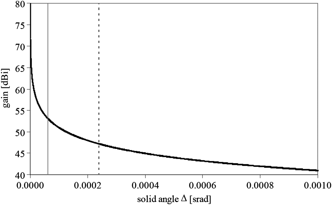
Fig. 1. Gain achievable over a given solid angle for an ideal antenna described by equation (4). Rectangular footprint as large as MTG control box (vertical solid line); circular footprint inscribing the MTG control box (vertical dashed line).
III. ONE-REFLECTOR ARCHITECTURE
A possible solution to cover the entire control box with the required antenna gain is based on a multi-beam architecture. In this scenario, one reflector is illuminated by a number of feeds generating different beams. This solution is well known since many years from broadcasting satellites (e.g. [Reference Doro, Cucci, Di Fausto and Roederer4, Reference Crone and Roederer5]) and it makes use of a cluster of feed placed in the focus of a reflector antenna, as depicted in Fig. 2. In addition, approaches of this type have been already used in a number of ground stations, as pioneered by torus antennas [Reference Hyde, Kreutel and Smith6] and more recent custom-shaped Cassegrain antennas [Reference Hay, Barker, Granet, Forsyth, Bird, Sprey and Greene7]. However, these types of systems provide several different beams with a minimum finite separation between adjacent beams (i.e. between adjacent satellites), which results into a non-uniform G/T coverage. Therefore, they would not meet the specifications required for the MTG satellites, where the G/T coverage must be as uniform as possible because each satellite can be at any position within the control box and with an arbitrarily small separation from adjacent satellites. Nevertheless, this type of architecture is further investigated in this paper to evaluate its potential as possible candidate for the MTG satellites, aiming to obtain the required uniform coverage while taking into account the imposed mechanical constraints previously discussed (i.e. standard circular reflectors and no mechanical or electrical beam steering).

Fig. 2. Schematic of the one-reflector multi-beam antenna architecture (drawing not to scale).
In order to study, analytically, the architecture depicted in Fig. 2 a numerical tool has been developed on the basis of well-known equations [3]. First, the illumination provided by each feed is considered, assuming that this illumination is independent from the position of the feed that generated the illumination itself. Although this hypothesis introduces an approximation and does not take into account the physical dimension imposed by a real feed, it allows for a fast analytical evaluation of the system behavior, leaving to further analyses the antenna refinement. Without losing generality, it is possible to assume that the illumination is linearly polarized along a certain direction, for example, the Y-axis in Fig. 2. Then, the x-component of the vector potential L (all other components are zero) is calculated:
where E y(x, y) is the y-component of the electric field along an imaginary plane in front of the reflector (i.e. the illumination), k is the wave number, u = sin θ cos ϕ and v = sin θ sin ϕ. The radiation intensity can then be derived as
where η is the vacuum impedance and λ is the working wavelength. Once the radiation intensity is known, the antenna gain for all sky directions is obtained by using equations (1) and (2). Then, a numerical routine based on simple geometrical rules makes use of the antenna gain to calculate the number of beams required to cover the control box with the specified gain.
From approaches already widely adopted for broadcasting satellites [Reference Doro, Cucci, Di Fausto and Roederer4, Reference Crone and Roederer5], it is well known that it may be possible to achieve an almost uniform coverage of the required control box with an illumination that can be conveniently described by a quasi-parabolic curve with a specific edge taper ρ, as depicted in Fig. 3. In particular, this type of illumination guarantees an extremely high value of illumination efficiency at the cost of low spillover efficiency. Despite this drawback, this kind of illumination yields an almost uniform coverage of the control box because it can be realized by small-aperture feeds that can be closely packed to each other [Reference Doro, Cucci, Di Fausto and Roederer4, Reference Crone and Roederer5]. Since the analytical model adopted to investigate this architecture can be implemented in a very fast numerical tool, it is possible to calculate the number of beams (i.e. the number of feeds) required to cover the control box for several different antenna diameters, minimum G/T over the control box and illumination edge taper ρ. Figure 4 shows the outcome of this analysis for a specific edge taper ρ = −2.5 dB, this value being the best option in terms of coverage uniformity; the results for other values are omitted for brevity.

Fig. 3. Schematic of the illumination provided by each feed of the one-reflector multi-beam antenna architecture.

Fig. 4. Number of beams required to cover the specified control box versus diameter of the main reflector for a given G/T. Illumination of the main reflector as in Fig. 3, edge taper ρ = −2.5 dB.
From Fig. 4, it is evident that a minimum number of feeds exist for a given G/T. This can be explained because of the basic properties of the radiation pattern generated by the main reflector. If the reflector diameter is too small, the gain provided by the antenna is not large enough to meet the required gain. For this reason, a threshold for the minimum diameter can be determined. Conversely, if the antenna diameter is too large, the beamwidth is so small that the antenna gain rapidly drops below the required gain, thus requiring a large number of beams to cover the entire control box. For example, if G/T = 33 dB/K is considered, the control box can be covered by an antenna with diameter D = 4 m and 12 feeds. The equivalent coverage is shown in Fig. 5, where the iso-curves of the G/T generated by each feed are shown.

Fig. 5. Theoretical coverage of the control box (dashed black rectangle) with a minimum G/T of 33 dB/K obtained with an antenna diameter of 4 m and 12 feeds. In all, 37 dB/K (solid light gray), 35 dB/K (solid medium gray), and 33 dB/K (solid dark gray) iso-curves are shown.
Once the optimum compromise between antenna diameter, number of feeds, and illumination edge taper is determined, the results obtained from the numerical tool based on the analytical model described in this paper are verified with a more accurate and time-consuming commercial numerical tool based on physical optics [8]. To this aim, 12 feeds are modeled as standard corrugated horns with an aperture of one wavelength (1.1 cm at 27 GHz) placed close to each other in the primary focus of a standard parabolic reflector antenna with a ratio between focus distance and diameter f/D = 0.75. This model guarantees that the illumination generated by the reflector antenna is practically equal to the illumination shown in Fig. 3, used for the analytical model. The results from the simulation for the case previously described (i.e. antenna diameter D = 4 m and 12 feeds) are shown in Fig. 6. The coverage in Fig. 6 can be considered in good agreement with the analytical coverage shown in Fig. 5. A small discrepancy of around 2 dB is noted (the minimum G/T obtained by the physical-optics-based tool is around 31 dB/K instead of the required 33 dB/K), but this is not considered a major problem at this stage since it could be partially recovered by further optimizations. Please also note that for completeness Fig. 6 is given in terms of u − v coordinates instead of latitude − longitude coordinates as in the case of Fig. 5. Of course, both representations can be adopted practically without distinction because, for the small angles of the control box (0.2 × 1.0° around equal to 0.0035 × 0.0175 rad), the sine of the angles can be considered equal to the angles themselves.

Fig. 6. Simulated coverage of the control box (dashed black rectangle) obtained with an antenna diameter of 4 m and 12 feeds. In all, 33 dB/K (solid light gray), 32 dB/K (solid medium gray), and 31 dB/K (solid dark gray) iso-curves are shown.
Although this solution demonstrates that it is possible to uniformly cover the control box, it cannot be considered fully satisfactory for the design constraints imposed by the MTG architecture. In fact, it is based on an illumination generating a significant amount of spillover, which means an increase in the noise temperature collected by the antenna. If for broadcasting satellites transmitting toward the Earth this issue can be ignored, for a receiving ground station pointing toward the sky it can be a critical point because the spillover from the main reflector directly collects noise from the Earth. Therefore, the noise temperature T = 21 dBK assumed for all these calculations (as reported in the previous section) would require further assessments and, probably, the installation of a more complicated receiving chain (i.e. a cryo-cooled LNA) to maintain the specified noise temperature. Since the use of a non-cryo LNA is considered mandatory, this potential solution is discarded.
IV. MULTI-REFLECTOR ARCHITECTURE
Reducing the illumination spillover, the noise temperature collected by the antenna can be maintained at the required level with the use of a non-cryo LNA. A more tapered illumination can be adopted by larger feed horns, placed close to each other in the focus of a parabolic reflector. However, it is well known that as soon as the feed horns are too large, the beams generated by each feed are separated by a significant angular distance and a uniform coverage of the control box cannot be obtained. Solutions already adopted for broadcasting satellites since many years still paved the road for a different approach [Reference Rao9]. In fact, if the different beams are generated by different reflectors, it will be possible to overcome the main restriction given by the physical dimension of the feed horns, which prevents a single reflector from generating a uniform coverage. In particular, the beams required to cover the control box are generated in such a way that each beam created by a certain reflector is interleaved with another beam created by another reflector, as illustrated schematically in Fig. 7 in the case of three reflectors.

Fig. 7. Schematic drawing of the multi-reflector multi-beam antenna architecture (drawing not to scale).
According to this approach, a new illumination can be used for the analytical analysis of the compromise between antenna diameter, required minimum G/T, and illumination law. In particular, the illumination adopted is illustrated in Fig. 8. Since now the major aim of the illumination is to provide good spillover efficiency while maintaining good illumination efficiency, a standard law based on a raised-cosine curve is an optimum choice. The calculated results are shown in Fig. 9. Of course, also adopting this new type of illumination it is evident that a minimum number of feeds exist for a given G/T. Moreover, considering the same example, G/T = 33 dB/K, it is noted that the minimum occurs for an antenna diameter D = 4 m and six feeds. The equivalent coverage is shown in Fig. 10, where the iso-curves of the G/T generated by each feed are shown.

Fig. 8. Schematic of the illumination provided by each feed of the multi-reflector multi-beam antenna architecture.

Fig. 9. Number of beams required to cover the specified control box versus diameter of the main reflector for a given G/T. Illumination of the main reflector as in Fig. 8.

Fig. 10. Theoretical coverage of the control box (dashed black rectangle) with a minimum G/T of 33 dB/K obtained with an antenna diameter of 4 m and six feeds. In all, 37 dB/K (solid light gray), 35 dB/K (solid medium gray), and 33 dB/K (solid dark gray) iso-curves are shown.
Therefore, the new illumination is able to provide a uniform coverage of the control box by using half of the feeds determined for the previous case. As discussed previously, this illumination can be provided by larger feed horns which, if placed together close to each other in the focus of the same antenna, would generate beams too much separated from each other to obtain a quasi-uniform coverage of the control box.
Conversely, if the six feeds are divided among different antennas, the angular regions not properly illuminated by the beams given by a certain reflector can be covered by other beams from other reflectors, achieving the required minimum gain all over the control box. In particular, two cases are studied: two antennas with three feeds each and three antennas with two feeds each, the latter shown in Fig. 7.
Both cases have been modeled in the physical-optics-based commercial tool and it has been verified that the most promising solution is the architecture based on three antennas with two feeds each. For each antenna, these three feeds are modeled as standard corrugated horns with an aperture of three wavelength (3.3 cm at 27 GHz) placed close to each other in the primary focus of a standard parabolic reflector with a ratio between focus distance and diameter f/D = 0.75. The results from the simulation are shown in Fig. 11 and the agreement with the analytical coverage shown in Fig. 10 can be considered excellent. In fact, the minimum required G/T = 33 dB/K is met and the spillover as calculated by the commercial tool is practically negligible, enabling a receiving chain based on non-cryo LNAs. Therefore, this type of solution can be considered a good candidate for the ground station supporting the MTG satellites.

Fig. 11. Simulated coverage of the control box (dashed black rectangle) obtained with three 4-m antennas with two feeds each. In all, 33 dB/K (solid light gray), 32 dB/K (solid medium gray), and 31 dB/K (solid dark gray) iso-curves are shown.
V. CONCLUSION
This paper has described and analyzed an approach for ground stations serving geostationary multi-satellite missions, such as the next generation of METEOSAT satellites, called MTG. The specific constraints imposed by the MTG satellites, in particular the high working frequencies (around 26 GHz), the need to cover with a uniform G/T the portion of the sky (called control box) where the satellites will fly, and the use of fixed (i.e. without any mechanical or electric beam steering) circular parabolic reflector antennas, required the study of a new architecture for the ground station.
It has been demonstrated that a system composed by three reflectors, each with two feeds, can meet the requirements. In particular, the three reflectors generate interleaved beams, in such a way that the control box is almost uniformly covered with the required G/T. In this way, there is no theoretical limit to the number of satellites that can be simultaneously supported and to the minimum separation between adjacent satellites. The latter advantage overcome a major problem affecting the most advanced fixed multi-beam ground stations actually adopted to support geostationary satellites.
The architecture has been analyzed by means of analytical equation implemented in a numerical tool and, as verification, by means of a physical-optics-based commercial software. The analytical approach has allowed for rapidly evaluating the best compromise in terms of antenna diameter, number of feed, type of illumination, and required G/T. Then, the use of more advanced software permitted verification of the results obtained for the optimum solution, obtaining good agreement between both methods.
ACKNOWLEDGEMENTS
This work has been carried out in a frame of a contract with EUMETSAT. The authors would like to thank Joaquín González and César Carmona from EUMETSAT for all useful discussions and support.
 Marco Pasian was born in 1980. He received his M.S. degree “Cum Laude” in electronic engineering and his Ph.D. in electronics and computer science from the University of Pavia, Pavia, Italy, in 2005 and 2009, respectively. He is currently a PostDoc of the Department of Electronics of the University of Pavia. His main research interests include periodic structures, antennas and microwave devices for space and defense applications. He spent a period at the European Space Agency, Darmstadt, Germany and at TNO, Defence, Security and Safety, The Hague, The Netherlands in 2004 and 2008, respectively. In 2005, he was with Carlo Gavazzi Space, Milano, Italy. He is member of the EuMA and of the IEEE. He serves as chair for the European Microwave Conferences and as reviewer for IEEE, EuMA and IET journals.
 Marta Cametti was born in Velletri, Italy, in 1983. She received her degree in telecommunications and electronic engineering in December 2004 and the M.S. degree in electronic engineering in October 2009 from the University of Pavia. She worked at her graduation thesis at the École Polytechnique of Montréal, Québec, Canada, for the “Design and testing of a radiometer system at 35 GHz.” In November 2009, she joined the Department of Electronics of the University of Pavia as a Ph.D. student in electronics. Her research activity is mainly focused on the study of reflector antennas for data communication with meteorological and deep-space satellites.
 Maurizio Bozzi was born in Voghera, Italy, in 1971. He received the “Laurea” degree in electronic engineering and the Ph.D. in electronics and computer science from the University of Pavia, Italy, in 1996 and 2000, respectively. In 2002, he joined the Department of Electronics, University of Pavia as an Assistant Professor in electromagnetics. He currently teaches the courses of “Numerical Techniques for Electromagnetics” and of “Computational Electromagnetics and Photonics.” He held research positions in various universities worldwide, including the Technical University of Darmstadt, Germany, the University of Valencia, Spain, the Polytechnic University of Montreal, Canada, and the Centre Tecnologic de Telecomunicacions de Catalunya (CTTC), Spain. His research activities concern the development of numerical methods for the electromagnetic modeling of microwave and millimeter-wave components. Prof. Bozzi received the Best Young Scientist Paper Award at the XXVII General Assembly of URSI in 2002, and the MECSA best paper award at the Italian Conference on Electromagnetics in 2000.
 Luca Perregrini received the “Laurea” degree in electronic engineering and Ph.D. in electronics and computer science from the University of Pavia, Italy, in 1989 and 1993, respectively. In 1992, he joined the Department of Electronics of the University of Pavia, where he is now an Associate Professor in electromagnetics. His main research interests include numerical methods for the analysis and optimization of waveguide circuits, frequency-selective surfaces, reflectarrays, and printed microwave circuits. He coauthored the textbook Fondamenti di Onde Elettromagnetiche (Milano, Italy, McGraw-Hill Italia, 2003). Prof. Perregrini was an Invited Professor at the Polytechnic University of Montreal, Montreal, Quebec, Canada in 2001, 2002, and 2004. He is a member of the General Assembly of the European Microwave Association for the period 2011–2013, of the Technical Program Committee of the European Microwave Conference since 2009 and of the Technical Program Committee of the IEEE International Microwave Symposium since 2003.
 Steve Rawson is the founder and director of Callisto, a small engineering company specialized in Ground Stations engineering and consultancy. Since founding Callisto in 1993 he has worked as a consultant to ESA and EUMETSAT on ground station project. He has also undertaken a number of study contracts for the Agency on cryogenic low-noise systems and noise temperature measurements. Prior to starting Callisto he worked in the UK for Serco in the role of consultant and project manager in a number of civil and military satellite communications projects. He started his career in 1981 as an engineer in the Grounds Stations division at ESOC, where he worked on a number of ESA projects including METEOSAT, Exosat and Giotto up to 1987.


