


Introduction
It is anticipated that future wireless systems will extensively utilize two main multi-antenna techniques, i.e. the multiple-input multiple-output (MIMO) and the beamforming [Reference Alexiou and Haardt1]. MIMO is commonly used to increase the capacity of a wireless channel by exploiting the spatial properties of a multipath environment; therefore, it is dedicated for non-line-of-sight (NLOS) conditions. In contrast, the beamforming is usually used to improve the gain in the line-of-sight (LOS) propagation. The beamforming can be realized with a phased antenna array (PAA) [Reference Mailloux2], a reconfigurable aperture [Reference Yashchyshyn, Derzakowski, Bogdan, Godziszewski, Nyzovets, Kim and Park3], or a digital signal processing. It can be also obtained with a time-modulated antenna array (TMAA) which is considered as an unconventional beamforming architecture [Reference Rocca, Oliveri, Mailloux and Massa4]. The TMAA concept was first proposed in 1959 [Reference Shanks and Bickmore5] as an alternative to the PAA because fast radio frequency (RF) switching allows similar weighting of RF signals and switches have several advantages over phase shifters [Reference Yashchyshyn, Godziszewski, Bogdan and Piasecki6]. However, in contrast to the PAA, output signal of the TMAA is spread into multiples of the modulation frequency around the center frequency. This phenomenon used to be considered as a disadvantage; therefore, many suppressing techniques have been proposed in the literature [Reference Drysdale, Allen and Okon7–Reference Yao, Wu and Fang9]. Nowadays, the peculiar properties of the sidebands are considered as useful in many applications, e.g. beam-steering [Reference Poli, Rocca, Oliveri and Massa10], spatial multiplexing [Reference Rocca, Zhu, Bekele, Yang and Massa11], direction finding [Reference He, Cao, Chen, Liang, Zhu, Geng and Jin12], MIMO radar [Reference Ni, Yang, Chen and Guo13], or MIMO communication [Reference Rocca, Poli, Bekele and Massa14]. In addition, the sidebands inherently generated by the TMAA can be utilized as virtual transmission channels in multipath scenarios [Reference Maneiro-Catoira, Brégains, García-Naya and Castedo15]. This approach was employed to devise a maximum ratio combiner [Reference Maneiro-Catoira, Brégains, García-Naya, Castedo, Rocca and Poli16], a compact single-RF MIMO receiver [Reference Gwak, Sohn and Lee17], and the beam-steering time-modulated MIMO (BS-TM-MIMO) receiver [Reference Bogdan, Godziszewski, Yashchyshyn and Kozłowski18]. Implementation of a wideband BS-TM-MIMO receiver, which supports processing of wideband signals up to 50 MHz, was presented in [Reference Bogdan, Godziszewski and Yashchyshyn19]. In this paper, which is a follow-up of [Reference Bogdan, Godziszewski, Yashchyshyn and Kozłowski18] and [Reference Bogdan, Godziszewski and Yashchyshyn19], we present an extended experimental investigation of the BS-TM-MIMO receiver operating indoor in a multipath propagation environment.
Time-modulated antenna array
Theoretical fundamentals
TMAAs are commonly referred to as 4D arrays, because time is utilized as an additional degree of freedom for beamforming. The time modulation is typically based on fast and periodic ON/OFF keying. In result, the beamforming and beam-steering, which have been traditionally related to PAAs, can be realized without phase-shifters. Various types of TMAAs were extensively elaborated in many scientific publications [Reference Rocca, Oliveri, Mailloux and Massa4–Reference Chen, Zhang, Wu and Fang28]; therefore, only a brief introduction to this topic will be provided in this paper. Properties of the TMAA will be described in the receiving mode without losing the generality. Figure 1 shows a typical configuration of a linear TMAA with a uniform spacing between elements distributed along the x-axis and SPST (single-pole single-throw) RF switches incorporated into a feed network. Figure 2 illustrates corresponding modulating functions, which are also referred to as switching sequences.
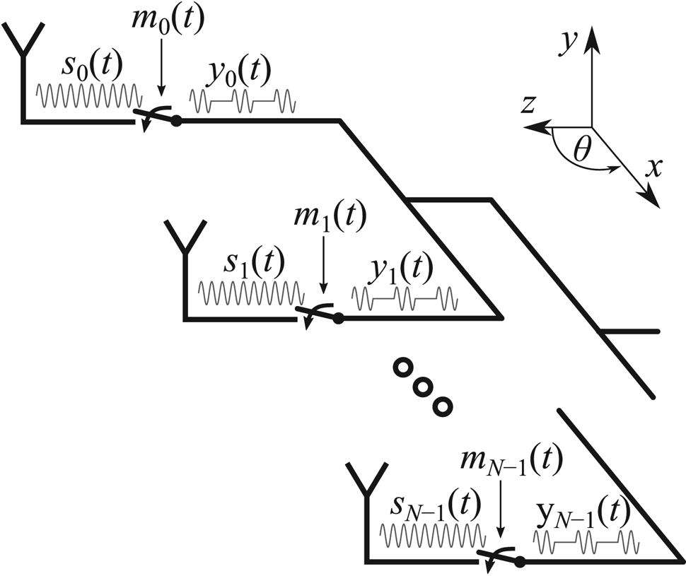
Fig. 1. Diagram of a linear TMAA with SPST switches.

Fig. 2. Unipolar switching sequences.
RF switches modulate (by means of a periodic ON/OFF keying) signals sn(t) delivered from each antenna, where n = 0…N–1 is the index of the antenna and N is the total number of antennas in the array. Operation of each switch can be expressed as a modulation of sn(t) by function mn(t), which is periodic and associate value of “0” for OFF and “1” for ON. All modulating functions share the same modulation frequency f 0 = 1/T 0, where T 0 is the period of modulation. Two constrains must be satisfied [Reference Maneiro-Catoira, Brégains, García-Naya and Castedo20]:
(1) the modulation frequency must be much smaller than the carrier frequency of an RF signal (f 0 << fc),
(2) the modulation frequency must be greater than the bandwidth of an RF signal (f 0 > B).
The TMAA array factor can be formulated as [Reference Rocca, Oliveri, Mailloux and Massa4]:

where Sn represents the complex excitation, d is the distance between antenna elements in the array, θ is the angle, and k = 2π/λ is the wave number. Due to its periodicity, mn(t) can be expressed in terms of a sum of complex Fourier series coefficient $M_n^{\lpar q \rpar }$ :
:


where ω 0 = 2π/T 0 and q ∈ (-∞, ∞). After substituting (2) into (1), the time-dependency is converted to the frequency-dependency and the array factor can be formulated as follows:

According to (4), the time-modulated signal is composed of a central component (q = 0) and sideband components (q ɛ ℤ, q ≠ 0). The latter are placed on multiplies of modulation frequency around the center frequency. Figure 3 presents an example of a bandpass signal's spectrum before (Fig. 3(a)) and after (Fig. 3(b)) time modulation. It shows that the sidebands are in fact spectral replicas of the original signal; however, they demonstrate different spatial properties because each sideband carries information received at frequency fc from a different angle [Reference Rocca, Zhu, Bekele, Yang and Massa11]. Therefore, sidebands can be utilized as diverse transmission channels [Reference Rocca, Poli, Bekele and Massa14–Reference Bogdan, Godziszewski and Yashchyshyn19].

Fig. 3. Spectrum of the signal (a) impinging upon TMAA; (b) at the output of TMAA.
Values of complex Fourier coefficients $M_n^{\lpar q \rpar }$ in (4) can be modified by adjusting the ON and OFF times of modulating functions. The beam-steering is obtained when switches are turned ON and OFF sequentially with some fixed delay with respect to the preceding one [Reference Bogdan, Bajurko and Yashchyshyn21]. Hence, operation of the n-th switch is related to the operation of the first switch in the following way:

where Δt is the delay progression. According to the time-shift property of the Fourier transform, the delay progression alters the phase of the Fourier coefficients as follows:

hence enables beamforming similarly to PAAs.
Design
The very first prototype of the TMAA was presented in 1963 [Reference Kummer, Villeneuve, Fong and Terrio22]. It was based on p-i-n diodes used as switches and demonstrated 10 kHz of the maximum signal bandwidth. Since then, over the last 50 years of progress in electronics and semiconductor technology, advanced switching devices with cutting edge performance have become available off-the-shelf. Moreover, more functional TMAA architectures with improved efficiency were proposed. For instance, the TMAA in [Reference Yao, Wu and Fang9] uses the I/Q channel modulator which is composed of two Wilkinson power dividers, two RF switches, two 0/π phase shifters in RF channels, and one π/2 fixed-phase shifter in the control circuit to realize a single-sideband time-modulated phase-only weighting. In [Reference Bogdan, Yashchyshyn and Jarzynka23], a less complex TMAA was presented because the 0/π phase shifters were avoided. Instead, a linear antenna array was complemented by identical, however, oppositely oriented antenna array and single-pole double-throw (SPDT) switches were used to alternate signals between elements of these two arrays as illustrated in Fig. 4. Such a design can be considered as a special case of the TMAA with bipolar squared periodic sequences [Reference Maneiro-Catoira, Brégains, García-Naya and Castedo24].

Fig. 4. Diagram of TMAA with SPDT switches connected to oppositely oriented antennas.
Each n-th pair of the oppositely oriented antennas can be treated as a single element of the linear array. Therefore, its radiation pattern in xz-plane can be calculated with equation (4). However, the Fourier coefficients $M_n^{\lpar q \rpar }$ have to be computed for the bipolar switching sequences presented in Fig. 5.

Fig. 5. Bipolar switching sequences.
The design of the TMAA used in the experiments is presented in Fig. 6. Details on the design and specification can be found in [Reference Bogdan, Godziszewski, Yashchyshyn, Kim and Hyun25]. The TMAA is composed of two layers: a superstrate with the permittivity of 2.2 (RT/duroid588) and a substrate with the permittivity of 3.66 (RO4003C). A single element of the array is composed of two oppositely oriented series-fed double-patch antennas. The elements are electromagnetically coupled with microstrip lines, which are connected to the throws of SPDT switches. The elements are designed for the center frequency of 5.6 GHz. Four elements are arranged in the form of a linear array.

Fig. 6. Design of the TMAA.
The RF switches ADRF5020 [26] are incorporated into the feed network. This particular model was selected because of its ultrashort switching time of 2 ns and a very good microwave performance at 5.6 GHz. The switching is periodic with repetition frequency f 0 = 50 MHz, or equivalently the repetition period of 20 ns. It is also uniform, i.e. each antenna in pair is active for 0.5T 0. The digital delay lines 3D3438 [27] are used to introduce delays between switching sequences. A step of the delay applied to switching sequences equals 60 ps which corresponds to 0.003T 0.
The total efficiency of the TMAA (ηT) can be estimated by taking into account the radiation efficiency (ηR), the switching efficiency (ηS), and the harmonic efficiency (ηH) [Reference Chen, Zhang, Wu and Fang28]. The radiation efficiency was estimated at 0.6 by considering the radiation efficiency of the antenna structure computed with an electromagnetic simulator and the insertion loss of the switch. The switching efficiency can be estimated at 1, because the SPDT switches always connect an element of the array to the feed network. Hence, the power of an RF signal is not dissipated in the matched load during the OFF state. The harmonic efficiency depends on the switching sequence and corresponding magnitudes of harmonics, according to:

Magnitudes of the harmonics are obtained after expressing the switching sequence in terms of the Fourier series. For example, magnitudes of the central component and the first negative harmonic for unipolar switching sequences presented in Fig. 2 equal |Mn (0)| = 0.5 and |Mn (−1)| = 0.3183, respectively. In our case, the TMAA is controlled by bipolar switching sequences presented in Fig. 5; hence the opposite antennas are excited with symmetrical unipolar RF pulses. Therefore, the harmonic efficiency obtained from (7) should be multiplied by two. This yields the harmonic efficiency of ηH (0) = 0.5 and ηH (−1) = 0.2 for the central component and the first negative harmonic, respectively. If the RF system is capable of processing multiple spectral components, then the harmonic efficiency is a sum of efficiencies calculated for each. For example, if both the central component and the first negative sideband component are processed, then the harmonic efficiency $\eta _H = \eta _H^{\lpar {-1} \rpar } + \eta _H^{\lpar 0 \rpar } = 0.7$ . Therefore, the total efficiency of the TMAA for MIMO can be estimated at η T = η Rη sη H = 0.42.
Figures 7(a)–7(c) show partial antenna patterns simulated for the first negative sideband (q = –1) and different values of the delay progression Δt. The beam-steering is performed in xz-plane. Figure 7(d) shows the antenna pattern at the central component (q = 0). It is divided by a deep broadside null into two beams, which are directed toward −24° and +24° in yz-plane. Comparing Figs 7(a)–7(d) one can observe that the antenna patterns simulated over the first negative sideband and the central component are complementary.

Fig. 7. Antenna patterns of TMAA simulated for (a) q = −1 and Δt = 0, (b) q = −1 and Δt = 0.15T 0, (c) q = −1 and Δt = 0.28T 0, (d) q = 0.
Concept and properties of BS-TM-MIMO
System design
Diagram of the 2 × 2 BS-TM-MIMO concept is presented in Fig. 8. The transmitting part resembles a regular 2 × 2 MIMO transmitter, i.e. two streams of symbols x1 and x2 are up-converted and sent from transmitting RF chains (Tx1 and Tx2) via omnidirectional dipole antennas. Waves transmitted from omnidirectional antennas propagate inside a multipath environment. The receiving part is modified with respect to a conventional 2 × 2 MIMO receiver in two ways. Firstly, only one receiving RF chain is used instead of two. Secondly, a single TMAA with the beam-steering is used instead of two separate antennas. This modification leads to a more compact and less power consuming design; however, a wider frequency band must be processed in the receiving RF chain. These modifications are possible, because TMAA converts spatial diversity into frequency diversity, i.e. combinations of waves approaching from different directions are available on different frequencies. For instance, waves approaching from xz-plane are available on odd sidebands (q = ±1, ±3, ±5, …) and waves approaching from yz-plane (excluding the broadside direction) are available at the center frequency (q = 0). Sidebands are demultiplexed in the baseband for further processing as diverse transmission channels.
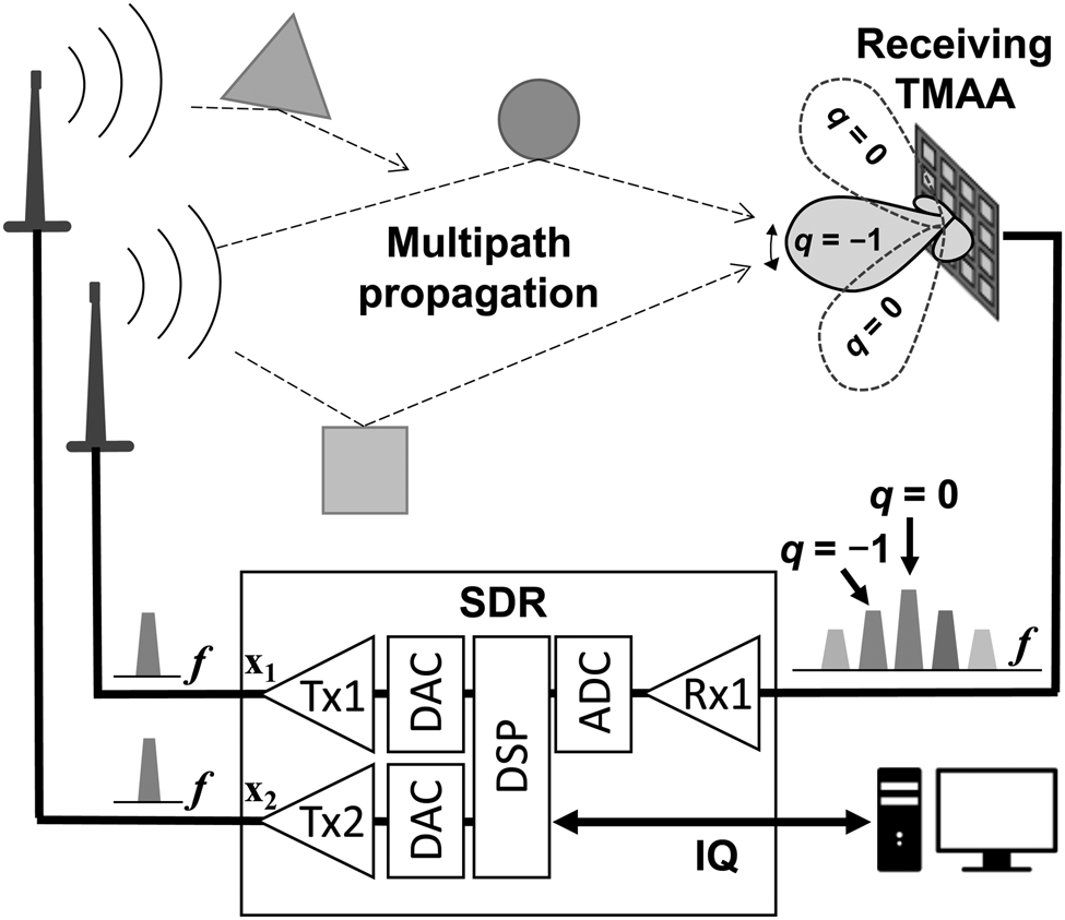
Fig. 8. Diagram of the BS-TM-MIMO.
Antenna pattern impact on MIMO performance
Two main requirements should be satisfied for an effective MIMO transmission. Firstly, a level of the signal to noise ratio (SNR) must be sufficiently high to correctly demodulate received symbols. Secondly, received signals should not be correlated. A level of the SNR can be increased by using directional antennas which provide higher gain than omnidirectional antennas, therefore can compensate for the path loss of a radio channel. Nevertheless, directional antennas reduce the angular spread of the channel, thus decrease the MIMO performance. Another solution is an adaptive antenna with a controllable pattern. Its beam can be focused toward a direction which provides a signal with high SNR and satisfactory multipath richness.
The requirement of a low correlation between spatial streams can be satisfied to some degree when antennas are dislocated on more than a quarter of the wavelength [Reference Foschini and Gans29]. Otherwise, the performance of MIMO may be significantly limited. The necessary diversity can be produced with distinct antenna patterns, i.e. highly orthogonal patterns create a low correlation, hence capacity gains are possible [Reference Jensen and Wallace30, Reference Saunders and Aragón-Zavala31]. Correlation between two antenna patterns can be expressed with an envelope correlation coefficient (ECC) [Reference Votis, Tatsis and Kostarakis32]

where $\overrightarrow {F_i} \lpar {\theta \comma \;\varphi } \rpar$ is the pattern of the i-th antenna. Value of the ECC ranges from <0.1 for low correlation to ~0.5 for the nominal, and >0.9 for the high correlation [Reference Foegelle33]. Figure 9 shows the ECC calculated for different pairs of TMAA antenna patterns. As given in Table 1, the patterns indicated with roman numbers from I to VII were simulated for the first negative sideband component (q = –1) and different Δt. Pattern VIII was simulated for the central component (q = 0). The lowest values of the ECC are obtained when pattern VIII is combined with any other, because of its divergent shape. In many applications, pattern VIII could be recognized as disadvantageous; however, in MIMO system, it can provide better diversity.

Fig. 9. ECC calculated for different pairs of TMAA antenna patterns.
Table 1. Direction of the main beam in terms of the elevation (θ) and azimuthal angles (φ) obtained for different TMAA configurations.

The ECC is a popular metric indicating the effectiveness of MIMO antennas; however, it does not consider the characteristic of a multipath environment. In practical cases, a condition number (κ) of the channel matrix is a more reliable indicator of the correlation between spatial streams. The condition number is calculated from the instantaneous channel matrix H without the need for stochastic averaging [34] according to:

where ${\hat{\bf H}}$ is an estimate of the channel matrix. A well-conditioned channel matrix indicates a low correlation between received signals and yields a low value of the condition number, which facilitates MIMO communication in the high SNR regime [Reference Tse and Viswanath35]. Such a condition is usually obtained in NLOS propagation when the LOS wave is significantly attenuated.
Experimental investigation
The experimental 2 × 2 spatial multiplexing MIMO setup is presented in Fig. 10. A software-defined radio (SDR) with two full-duplex wideband transceivers was used as the RF front-end. Both transceivers cover frequencies from 10 MHz to 6 GHz with 160 MHz of analogue bandwidth. In addition, they are coherent and phase-aligned which facilitate the development of MIMO applications [36]. Two transmitting RF chains of the SDR were configured to upconvert and transmit the quadrature phase shift keying symbols at 5.6 GHz via two dipole antennas. A single receiving RF chain of the SDR was configured to downconvert and sample a wideband signal from the TMAA in a frequency range 5.5–5.7 GHz. This band included the first negative sideband component at 5.55 GHz, the central component 5.6 GHz, and the first positive sideband component at 5.65 GHz. The central component (q = 0) and the first negative sideband component (q = –1) were selected for further processing because, according to Fig. 9, antenna patterns related to these components give the lowest ECC. More details about the setup can be found in [Reference Bogdan, Godziszewski and Yashchyshyn19].

Fig. 10. Experimental setup composed of two dipole antennas, SDR, and the TMAA.
The primary purpose of the experimental investigation was to make a qualitative evaluation of the BS-TM-MIMO receiver operating in a typical indoor environment. Performance of the receiving system was assessed by calculating two fundamental metrics: the bit error rate (BER) and the condition number of the channel matrix. The experiments were conducted inside a room with tables, chairs, and desktop computers located next to the walls. The plan of the room is presented in Fig. 11. Two transmitting dipole antennas were located 0.6 m above the floor and 1.2 m beside the wall. The distance between dipole antennas was 22 cm ≈ 4λ. The experiments were conducted in various locations, although in this paper, we only discuss the results of the two most representative cases which are designated in Fig. 11 as Scenario 1 and Scenario 2. In both scenarios, the MIMO transmission was assessed in 101 different configurations. In all of the configurations, the central component pattern was fixed; although different antenna patterns were configured over the first negative sideband (q = –1), i.e. the main beam was steered from −50° to +50°. In addition, each configuration was tested 100 times in order to obtain statistically reliable data. Experiments were conducted in a non-isolated environment, hence the transmission was subject to spontaneous interferences from wireless local area networks (e.g. IEEE 802.11n/ac) operating in 5 GHz band. Therefore, in order to remove corrupted data, the frames of which the BER was 10 times higher than the minimum value obtained in a given configuration were removed.

Fig. 11. Experimental scenarios.
Figure 12(a) shows the minimum, the median, and the minimum to maximum range of the BER measured in Scenario 1 for different configurations of the TMAA (−0.468T 0 < Δt < 0.468T 0). Figure 12(b) presents the condition number calculated in each configuration. Annotations of Figs 12(a)–12(d) designate four representative cases. The antenna patterns and the in-phase and quadrature (IQ) samples for these cases are presented in Figs 13 and 14, respectively. If Δt is negative, then the main beam is directed away from the transmitting dipoles as presented in Fig. 11.

Fig. 12. Scenario 1 (a) BER; (b) condition number.

Fig. 13. Antenna patterns at the first negative sideband (q = –1) for selected TMAA configurations.

Fig. 14. IQ samples obtained from the first negative sideband (q = –1) for (a) Δt = –0.36T 0; (b) Δt = –0.117T 0; (c) Δt = 0.189T 0; (d) Δt = 0.369T 0.
Hence, the LOS component is significantly attenuated, and the received signal is mainly a combination of waves reflected from objects and walls of the room. Despite the fact that the signal power level is relatively low, the BER remains stable on a low level around 3 × 10⁻⁴ for Δt < −0.261T 0. This indicates good performance of MIMO and low correlation of streams, which is also confirmed by a low value of the condition number κ = 4.5 dB in configuration A. In case B (Δt = −0.117T 0), the main beam is directed toward a corner of the room behind a pillar which is hardly reachable by reflections. According to Fig. 14(b), the amplitude of symbols is smaller compared to Fig. 14(a) which indicates lower power of the received signal and leads to degradation of the BER. High value of the condition number (κ > 15 dB) indicates that the channel matrix is ill-conditioned, i.e. LOS component is dominating, although weak because it is received by a sidelobe. The median of the BER recovers for Δt = 0.036T 0. It remains stable around 5 × 10⁻⁴, however the minimum to maximum range is extended. In case C (Δt = 0.189T 0), the main beam is directed toward 20°. Hence, the received signal is mainly composed of strong reflections from oppositely located objects and the wall. The power of received signal increases for Δt > 0.189T 0 because the main beam is moving toward the direction of transmitting dipoles. Nevertheless, in case D (Δt = 0.369T 0), when the main beam is directed toward 40°, despite the high signal level (Fig. 14(d)), both the BER and the condition number increase noticeably. This effect is most probably a consequence of a more significant role of the LOS component against NLOS multipaths.
In Scenario 2, the TMAA was placed on the opposite side of the room as shown in Fig. 11. Obtained values of the BER and condition number are presented in Fig. 15. The results correspond to observations and conclusion drawn for Scenario 1.

Fig. 15. Scenario 2 (a) BER; (b) condition number.
Conclusion
Experimental results presented in this paper show the performance of the 2 × 2 MIMO receiver based on the TMAA and a single RF chain. Two spectral replicas generated inherently by the TMAA were effectively used instead of two conventional antennas with separate RF chains. Diversity of the spectral replicas was obtained by the spatial orthogonality of the antenna patterns. The beam-steering functionality of the TMAA was used to adapt to a multipath environment. Results of the conducted experiments show that the TMAA can be used to decrease the condition number of a channel matrix, hence, to reduce the number of transmission errors which leads to an improved performance of a 2 × 2 MIMO system.
Acknowledgement
This work was supported by the Faculty of Electronics and Information Technology, Warsaw University of Technology under grant number IRiTM/2018/9.
 Grzegorz Bogdan received his M.Sc. and Ph.D. degrees in telecommunications from the Warsaw University of Technology (WUT), Poland in 2013 and 2019, respectively. Since 2019 he is an Assistant Professor at WUT in the Institute of Radioelectronics and Multimedia Technology of the Faculty of Electronics and Information Technology. His main research interests are the design and optimization of adaptive antenna arrays and wireless communication systems.
 Konrad Godziszewski received his Ph.D. degree in telecommunications from the Warsaw University of Technology (WUT), Poland in 2018. He joined the Institute of Radioelectronics and Multimedia Technology, WUT, in 2013 where he is currently an Assistant Professor. His current research interests include antennas, material characterization in sub-terahertz frequency range, and ferroelectric materials.
 Yevhen Yashchyshyn received the M.E. degree from Lviv Polytechnic National University, Lviv, Ukraine, in 1979, the Ph.D. degree from Moscow Institute of Electronics and Mathematics (MIEM), Moscow, Russia, in 1986, and the D.Sc. (Habilitation) degree from Warsaw University of Technology (WUT), Warsaw, Poland, in 2006. In 2016, he was promoted to a Professor Title. Since 1999 he has been with the Institute of Radioelectronics and Multimedia Technology, WUT, where he is currently a Professor. He has authored over 250 technical papers, authored or co-authored five books, and holds a few patents. His current research interests include antenna theory and techniques, smart beamforming, reconfigurable antennas, radio over fiber techniques, and materials characterization, including ferroelectric ceramic-polymers composites investigation up to subterahertz frequency. In 2008, Professor Yashchyshyn was the recipient of the First Prize of EuMA at the 11th European Microwave Week, Amsterdam, the Netherlands, for his new concept of the reconfigurable antenna.


