Introduction
The improved spectral efficiency is one of the major goals/requirements for next generation wireless networks (5 G) to achieve higher data rates or throughputs. The in-band full duplex (IBFD) also termed as single channel full duplex transceivers based on monostatic antenna architecture (same antenna for transmit-Tx and receive-Rx operation) has the potential of theoretically doubling the spectral efficiency compared to conventional time and frequency duplexing schemes [Reference Sabharwal, Schniter, Guo, Bliss, Rangarajan and Wichman1–Reference Li, Masmoudi and Ngoc6]. Furthermore, the simultaneous transmit and receive (STAR) operation in the same range of frequencies can resolve several issues effectively in conventional wireless communication networks and commercial of the shelf multi-in multi-out (MIMO) transceivers can be used for the implementation of STAR transceivers [Reference Liao, Song and Han7, Reference Choi, Jain, Srinivasan, Levis and Katti8].
In conventional frequency division duplexing systems based on single antenna architecture, a duplexer is employed in order to separate Tx and Rx signals. However, the conventional duplexers cannot be used for IBFD operation as the interport isolation of such duplexer is severely degraded when transmission and reception is accomplished at the same frequencies as indicated in Fig. 1. The resulting very large amount of self-interference (SI) from transmitter (Tx) to its own receiver (Rx) is the major issue which hinders the practical realization of IBFD wireless communication [Reference Sabharwal, Schniter, Guo, Bliss, Rangarajan and Wichman1–Reference Maraševic, Zhou, Krishnaswamy, Zhong and Zussman3]. The high power SI signal overpowers the very weak received signal of interest (SOI) and results in severe degradation in signal to noise ratio (SNR) for intended wireless link [Reference Korpi, Riihonen, Syrjälä, Anttila, Valkama and Wichman9]. These high power SI signals are comprised of both linear and non-linear components resulting from direct coupling between Tx and Rx chains in addition to SI generated from environmental reflections or nearby objects [Reference Anttila, Korpi, Syrjälä and Valkama10].
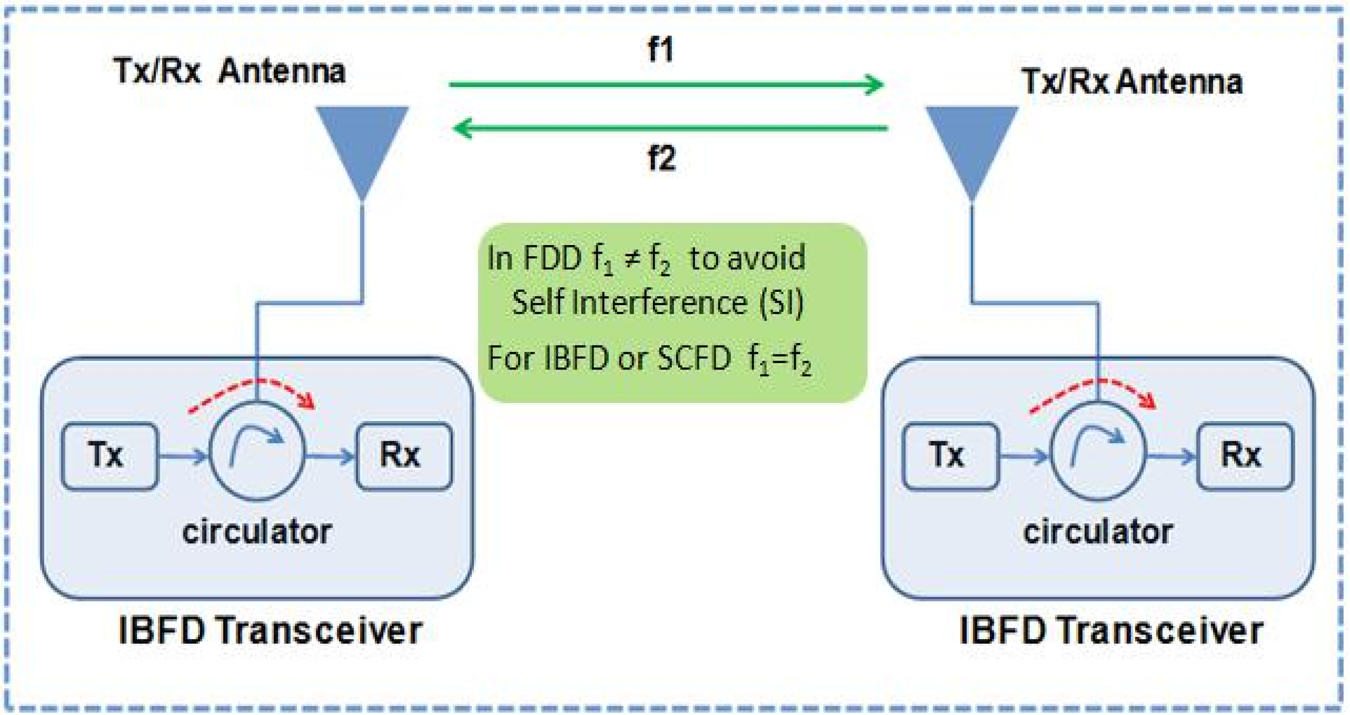
Fig. 1. IBFD wireless communication through STAR operation at the same frequency by using a monostatic antenna configuration.
An effective mechanism to suppress the SI which is usually termed as self-interference cancellation (SIC) is required on Rx side to retrieve the SOI for successful IBFD communication [Reference Korpi, Riihonen, Syrjälä, Anttila, Valkama and Wichman9, Reference Anttila, Korpi, Syrjälä and Valkama10]. Normally a large amount of SIC is required to suppress the SI to receiver's noise floor. These intended SIC levels are defined by radiated power (transmit power), noise figure (NF), and bandwidth of IBFD transceiver [Reference Korpi, Riihonen, Syrjälä, Anttila, Valkama and Wichman9]. For example, as computed below, >110 dB SIC is required for a radio transceiver transmitting +20 dBm power (P T), 20 MHz bandwidth (B.W), and NF of 11 dB for such transceiver [Reference Korpi, Riihonen, Syrjälä, Anttila, Valkama and Wichman9]:
 $$\eqalign{{\rm Noise\;floor\;}\lpar P_{\rm N}\rpar = & -174\,{\rm dBm} + 10{\rm log}\lpar {{\rm B}.{\rm W}} \rpar + {\rm NF} \cr = & -174\,{\rm dBm} + 73 + 11 ={-}90\,{\rm dBm}} $$
 $${\rm Required\;SIC\;Levels} = P_{\rm T}-P_{{\rm \;N}} = 20 + 90 = 110\,{\rm dB\;}$$
The SIC levels stated in (2) are intended to fully suppress the SI to the receiver's noise floor (−90 dBm for this example as illustrated in Fig. 2). As clear from (2), required SIC levels are directly related to Tx power i.e. high Tx power levels require more SIC to realize IBFD operation. Conversely, a low Tx power can relax the required amount of SIC, however, the reduced Tx power will decrease the range or coverage of wireless transmitter.
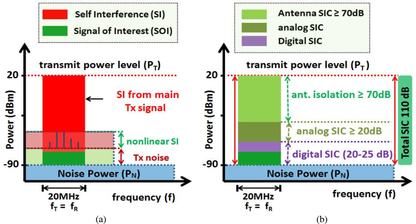
Fig. 2. (a) SI components (b) around 110 dB SIC for the monostatic antenna based transceiver when antenna interport isolation ≥70 dB within 20 MHz bandwidth.
These high levels of required isolation can be accomplished through multiple SIC topologies which can be deployed at various stages across the IBFD transceiver [Reference Hong, Brand, Choi, Jain, Mehlman, Katti and Levis11]. Normally, theses topologies utilize SIC at an antenna stage and techniques based on SIC in an analog/radio frequency (RF) and digital baseband domain [Reference Nawaz and Tekin12] as illustrated in Fig. 2. Moreover, a comparatively high amount of SIC is required at receiver's front end to prevent the saturation of the receive chain from very strong SI signals [Reference Anttila, Korpi, Syrjälä and Valkama10, Reference van den Broek, Klumperink and Nauta13]. In addition, a monostatic antenna with high interport isolation plays a critical role in achieving required SIC levels for the realization of a compact transceiver as it alleviates the SIC requirements at subsequent stages. In general, time or frequency based digital domain SIC techniques offer 20–25 dB SIC levels [Reference Amjad, Nawaz, Özsoy, Gürbüz and Tekin14, Reference Nawaz and Tekin15]. Moreover, a single-tap, signal inversion based analog/RF domain can achieve >20 dB isolation within 20 MHz bandwidth for the monostatic antenna configuration. Thus, exploiting a monostatic antenna capable of providing 65–70 dB interport isolation plays a vital role in achieving required SIC levels of 110–115 dB for the IBFD transceiver based on monostatic antenna architecture as illustrated in Fig. 2. Moreover, such a high interport isolation antenna at transceiver's front end can provide flexibility of deploying additional SIC stages for improved Tx –Rx isolation, especially, for high Tx power cases where more SIC levels are required as obvious from (2). Furthermore, the use of a monostatic IBFD antenna array provides improved gain to extend the coverage and reliability of communication link for specified receiver's sensitivity under given SNR values without additional SIC requirements at the Rx side of the IBFD transceiver.
Although, the bistatic antenna configuration (separate antenna elements for Tx and Rx operation) can be deployed with the IBFD transceiver where the inter-antenna spacing (spatial isolation) achieves the reduced coupling between Tx and Rx channels. In addition, the Tx and Rx operation can be performed with orthogonal polarization to achieve improved propagation domain isolation through the polarization diversity mechanism. However, deploying separate antenna elements for Tx and Rx operation weakens the real motive of IBFD topology as the bistatic antenna configuration itself can improve the throughput of conventional half duplex MIMO (multi-input multi-output) systems [Reference Knox16]. Furthermore, the bistatic antenna configuration requires more spacing (especially for improved Tx–Rx isolation) which impedes the realization of compact transceiver modules. Conversely, the IBFD transceiver based on monostatic antenna architecture (shared radiator for Tx and Rx operation) can be realized with a small form-factor (reduced size) to achieve all the potential gains of IBFD communication [Reference Knox16]. However, such a monostatic IBFD antenna system should provide high Tx–Rx interport isolation through SIC at the RF front end to prevent the saturation of analog to digital converter in the Rx chain from very strong RF signals of the co-located transmitter [Reference Korpi, Riihonen, Syrjälä, Anttila, Valkama and Wichman9, Reference Duarte, Dick and Sabharwal17].
Various techniques have been exploited previously in order to improve the interport isolation of monostatic antennas for IBFD applications. These techniques include polarization diversity [Reference Wu, Cheng and Fan18–Reference Zhou, Huang, Chio, Yang and Wei22] and hybrid techniques based on utilizing different modes and polarizations [Reference Etellisi, Elmansouri and Filipovic23]. The techniques based on polarization diversity in conjunction with additional SIC approaches have attracted much attention in recent days to realize IBFD antennas with relatively compact dimensions (small form factors). Such monostatic antennas have dual polarized characteristics where horizontal and vertical polarizations (TM01 and TM10 modes) are excited through perpendicularly placed feeds. This basic configuration of this sort of polarization diversity provides ~35–40 dB isolation between Tx and Rx ports. The additional SIC approaches are be utilized with such dual polarized antennas for improved isolation. For instance, ~20 dB additional isolation has been achieved through a defected ground structure for the work reported in [Reference Younkyu, Seong-Sik, Ahn, Jae-Ick and Itoh24]. Moreover, multilayered printed patch antennas with hybrid feeding structures can provide 15–20 dB improvement in Tx–Rx isolation for IBFD applications [Reference Nawaz and Tekin15, Reference Deng, Li, Zhang and Feng25, Reference Rikuta and Arai26]. In addition, differential feeding is one of the prominent SIC technique to achieve very nice interport isolation for dual polarized monostatic antennas [Reference Nawaz and Tekin27–Reference Nawaz and Tekin29]. The well-known signal inversion based analog/RF domain SIC techniques are also used with dual polarized antennas for isolation improvements [Reference Kolodziej, McMichael and Perry30–Reference Khaledian, Farzami, Smida and Erricolo33]. For example, an RF-SIC circuit plus a circulator has been used in [Reference Khaledian, Farzami, Smida and Erricolo33] to obtain >40 dB SIC for 65 MHz bandwidth.
In this paper, a dual-polarized 1 × 2 monostatic antenna array has been studied for 2.4 GHz applications where high Tx–Rx isolation has been achieved through well balanced differential feeding network at the Rx port. The proposed differential feeding at the Rx port effectively suppresses the RF leakage from the Tx port to present high interport isolation. A very simple 3 dB/180° ring hybrid coupler having nice amplitude and phase balance characteristics has been used for required differential feeding at the Rx port. The proposed differential feeding based SIC scheme has been mathematically described which achieves high Tx–Rx isolation without affecting the radiation characteristics of the presented antenna array. The effect of magnitude and phase imbalances of differential circuit on SIC levels is also illustrated analytically. A prototype of a compact 1 × 2 antenna array has been realized by implementing a dual polarized 1 × 2 antenna array with an integrated differential feeding network on a single layered printed circuit board (PCB). The implemented compact antenna array has been experimentally characterized. The measurement results demonstrate >30–35 dB additional isolation on the top of ~35 dB intrinsic isolation of polarization diversity for the dual polarized antenna array. The measured interport isolation for the implemented antenna array is >65 dB within a 10 dB return-loss impedance bandwidth of 50 MHz. In addition, the differential feeding at the Rx port suppresses the inter-element or mutual coupling to reduce side lobe levels (SLL).
The rest of this paper is organized as follows. Section “Differential feeding based SIC scheme for 1 × 2 IBFD antenna array” describes the array antenna architecture and describes the differential feeding based SIC topology for the proposed 1 × 2 array antenna. The proposed differential fed SIC scheme is also mathematically described in this section and dependence of SIC levels on characteristics of differential circuit is also illustrated. The design and simulation results for the compact differential fed array antenna are presented and discussed in section “Design and simulation results for compact differential fed 1 × 2 antenna array”. The section “Measurement results for compact differential fed 1 × 2 IBFD antenna array” presents the test and measurement results for implemented prototype of the antenna array, followed by conclusions in section “Conclusion”.
Differential feeding based SIC scheme for 1 × 2 IBFD antenna array
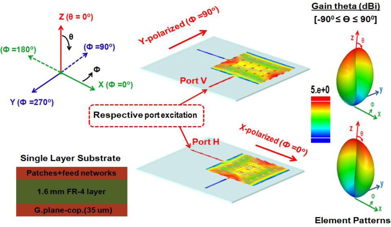
The proposed 2.4 GHz antenna array is shown in Fig. 3 which is comprised of two radiating patches with inter-element spacing of λ o/4 = 31.25 mm where λ o corresponds to the free space wavelength for 2.4 GHz frequency. The squared-shaped radiating elements characterize the same resonant frequencies of 2.4 GHz for Tx and Rx ports for intended IBFD operation. The proposed antenna array has been designed on a single layer, 1.6 mm thick FR-4 substrate (ɛ r = 4.4, tanδ = 0.02) as illustrated in Fig. 3. The optimized dimensions for the proposed array are also shown in Fig. 3. The symmetrically placed Rx ports with respect to the Tx port (through 3 dB/0o power divider) produce the same amount of SI from the Tx port to both Rx ports.
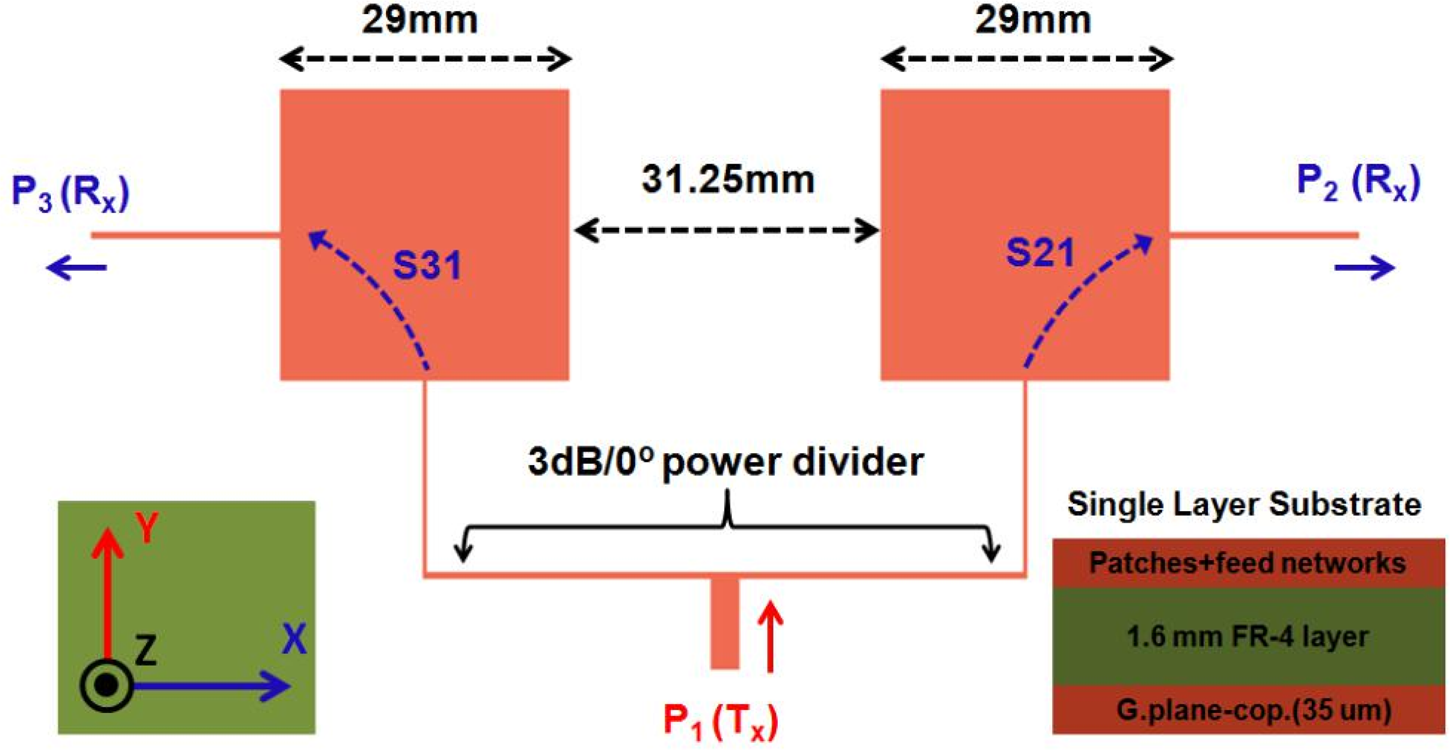
Fig. 3. The proposed 2.4 GHz dual polarized antenna array of two radiating patches with inter-element spacing of λ o/4 = 31.25 mm (λ o is the free space wavelength for 2.4 GHz frequency).
As clear from the structure of the proposed antenna array in Fig. 3, each radiating patch of array is excited from two orthogonally placed thin quarter-wave feeds which are connected at the center of the respective edge of the square-shaped patch. Consequently, each element will radiate with dual polarized characteristics when excited from respective Tx and Rx ports. This sort of feeding achieves the maximum Tx–Rx isolation at a required frequency through polarization diversity. This fact is illustrated and endorsed with simulated element gain patterns and surface current distributions for respective Tx/Rx port excitations as shown in Fig. 4.

Fig. 4. The gain patterns and surface current distributions for dual polarized, single element (patch) of the proposed 1 × 2 antenna array (designed on a 1.6 mm thick FR-4 substrate).
Our proposed SIC scheme is based on employing a differential feeding through both Rx ports (P 2 and P 3) of the proposed dual polarized, 1 × 2 antenna array (which has been shown in Fig. 3) for effective suppression of SI resulted from the Tx port (P 1). The presented proposed SIC scheme achieves high Tx–Rx interport isolation without affecting the radiation characteristics (gain performance etc) of the antenna array as clear from following analysis. The phasor-form representation of linear polarized electric field vectors (E) for Tx and Rx ports of the proposed dual polarized 1 × 2 antenna array (as presented in Fig. 3) can be expressed as:
 $${\bi E}_{Tx} = {\bi E}_{\bi m}{\rm \;}\lpar {\hat{{\bi y}}} \rpar \quad {\rm and}\quad {\bi E}_{Rx2} = {\bi E}_{\bi m}{\rm \;}\lpar {\hat{{\bi x}}} \rpar {\rm \comma \;}{\bi \;}{\bi E}_{Rx3} = {\bi E}_{\bi m}{\rm \;}\lpar {-\hat{{\bi x}}} \rpar $$
As stated earlier, our proposed SIC scheme is based on differential excitation of both Rx ports (P 2 and P 3) of the proposed dual polarized 1 × 2 antenna array, in that case, the electric field vector (E) for the differential fed Rx mode can be expressed as:
 $${\bi E}_{R_x} = {\bi \;}{\bi E}_{Rx2} + {\rm e}^{\,j{180}^\circ }{\bi E}_{Rx3}{\rm \;} = {\bi E}_{\bi m}\lpar {\hat{{\bi x}}} \rpar -{\bi E}_{\bi m}{\rm \;}\lpar {-\hat{{\bi x}}} \rpar = 2 \times {\bi E}_{\bi m}{\rm \;}\lpar {\hat{{\bi x}}} \rpar $$
where  $\hat{{\bi x}}$ and
  $\hat{\bi {y}}$ are unit vectors along x and y respectively and Em is the amplitude of E field.
As clear from (4), the fields radiated by both elements of the array antenna are combined in phase when differential feeding through both Rx ports of the proposed antenna array is employed. Consequently, the presented 1 × 2 antenna array with differential Rx mode will transmit and receive with vertical and horizontal polarizations respectively as clear from (3) and (4).
The SIC capabilities of the proposed scheme for the dual polarized 1 × 2 antenna array can be described through very simple mathematical analysis as follows. We assume that ITx, IRx 2, and IRx 3 denote the currents for respective Tx and Rx ports as indicated in Fig. 3, then:
 $${\bi \;}I_{Rx2} = {\bi \;}I_{T_x}\;S_{21}\quad {\rm and}\quad I_{Rx3} = {\bi \;}I_{T_x}\;S_{31}$$
For differential excitation, the total current IRx flowing out from the differential Rx port is:
 $$I_{Rx} = {\rm \;}\displaystyle{1 \over {\sqrt 2 }}\lpar {{\rm}e^{\,j{180}^{\rm o}}I_{Rx2{\rm \;}} + I_{Rx3}} \rpar = \displaystyle{{{\bi \;}I_{Tx}} \over {\sqrt 2 }}\lpar {{\rm \;}S_{31{\rm \;}}-S_{21}} \rpar $$
The Tx–Rx interport current isolation (inverted current coupling ratio) is given as:
 $$\displaystyle{{{\bi \;}I_{Tx}} \over {{\bi \;}I_{Rx}}} = \displaystyle{1 \over {\lpar S_{31}-S_{21}\rpar }}$$
As stated earlier and clear from Fig. 3, the same levels of RF coupling (SI) is resulted from the Tx port to both Rx ports due to symmetry of the proposed structure for the dual polarized antenna array. In other words S 21 = S 31 to offer infinite Tx–Rx interport isolation theoretically based on mathematically established SIC condition in (7). However, for practical differential fed, dual polarized antenna array S 21 ≈ S 31 (due to the non-ideal layout and imperfect excitations) and high levels of SIC can be achieved when a differential circuit having nice amplitude and phase balance characteristics are employed with the proposed dual polarized antenna array. In addition, the differential feeding suppresses the mutual coupling between antenna elements which improves antenna gain and polarization purity through reduced SLL levels [Reference Liang, Zhong and Wang34].
The achievable SIC levels and Tx–Rx isolation bandwidth are highly dependent on characteristics of the employed differential feeding network (circuit). This dependence can be quantitatively analyzed for SIC levels for two equal-magnitudes out of phase sinusoidal signals. Figure 5 presents the computed SIC levels under various magnitude and phase errors between two signals. The achieved levels of SIC are greatly influenced by both magnitude and phase errors between two signals which corresponds to magnitude and phase imbalances of the differential feeding network. For instance, as illustrated in Fig. 5, the SIC levels are reduced from 45 to 30 dB when phase error is varied from 0 to ±2° for 0.1 dB magnitude error curve. Similarly, if magnitude error is increased from 0.1 to 0.3 dB, the corresponding SIC levels are reduced from 45 to 35 dB with zero phase error in both cases. We have used a 3 dB/180° ring hybrid coupler as a differential circuit with nice amplitude and phase balance characteristics to achieve improved SIC levels for the proposed differential fed antenna array.
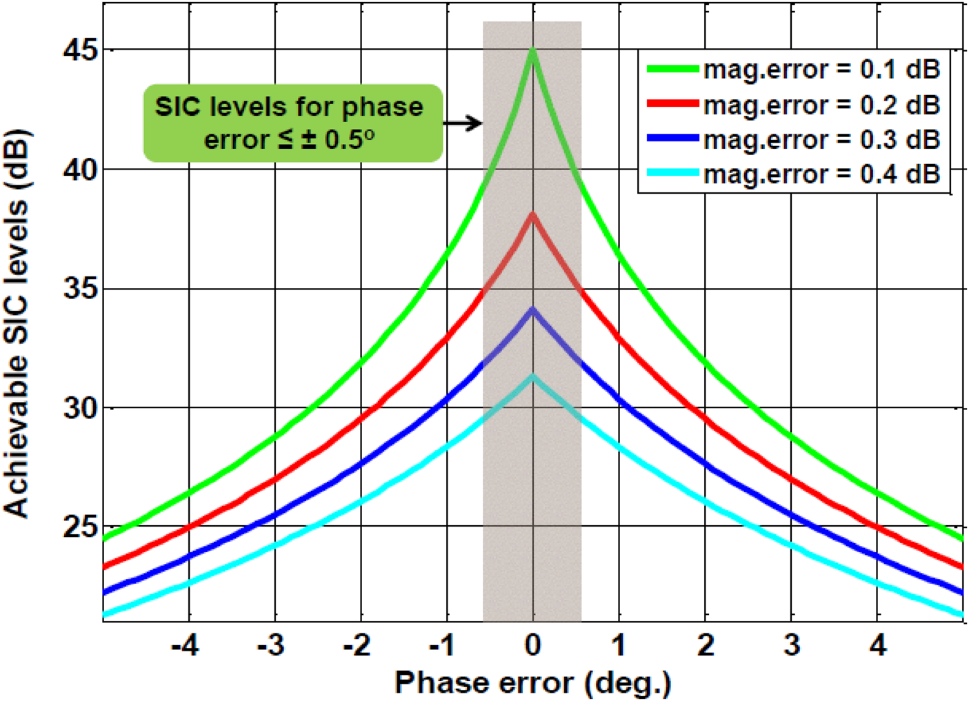
Fig. 5. The computed SIC levels under various magnitude & phase errors between two signals.
Design and simulation results for compact differential fed 1 × 2 antenna array
The simulated return-loss (S 11, S 22, and S 33) and interport isolation results (S 21, S 31, and S 31–S 21) for the 1 × 2 antenna array are presented in Fig. 6. As stated earlier and clear from simulation results in Fig. 6, the polarization diversity provides ~35 dB interport isolation (S 21, S 31) for the presented antenna array. The differential feeding through both Rx ports can provide additional isolation as clear from (S 31–S 21) results in Fig. 6. The ideal differential feeding network (having zero magnitude and phase errors) can demonstrate peak Tx–Rx interport isolation >120 dB and around 90 dB isolation in 60 MHz. However, better than 80 dB isolation in 60 MHz is achieved with our proposed hybrid coupler as a differential circuit as clear from Fig. 6.
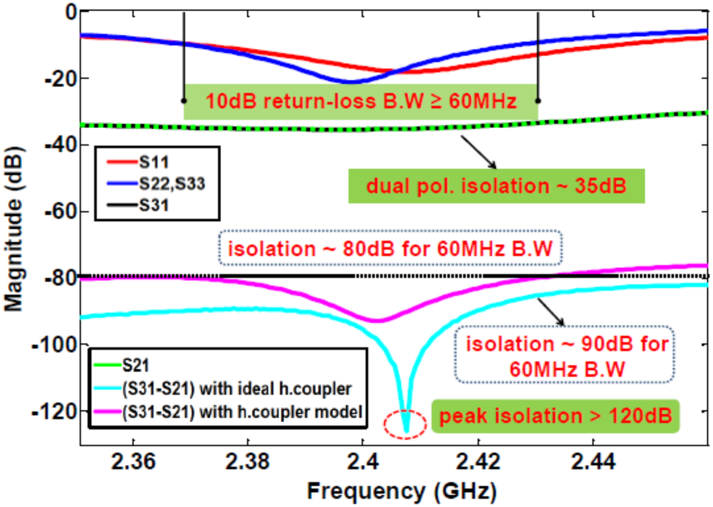
Fig. 6. The simulated return loss (S 11, S 22, and S 33) and interport isolation (S 21, S 31, and S 31–S 21) results for the proposed 1 × 2 dual polarized 2.4 GHz antenna array.
The intended differential Rx mode operation has been realized by using a 2.4 GHz, 3 dB/180° ring hybrid coupler. The ring hybrid coupler performs as a 3 dB out of phase power combiner for required SIC operation when it is connected with the proposed array where a difference port (Δ port) designated as P 2 of the hybrid coupler is used for the Rx port as indicated in Fig. 7.
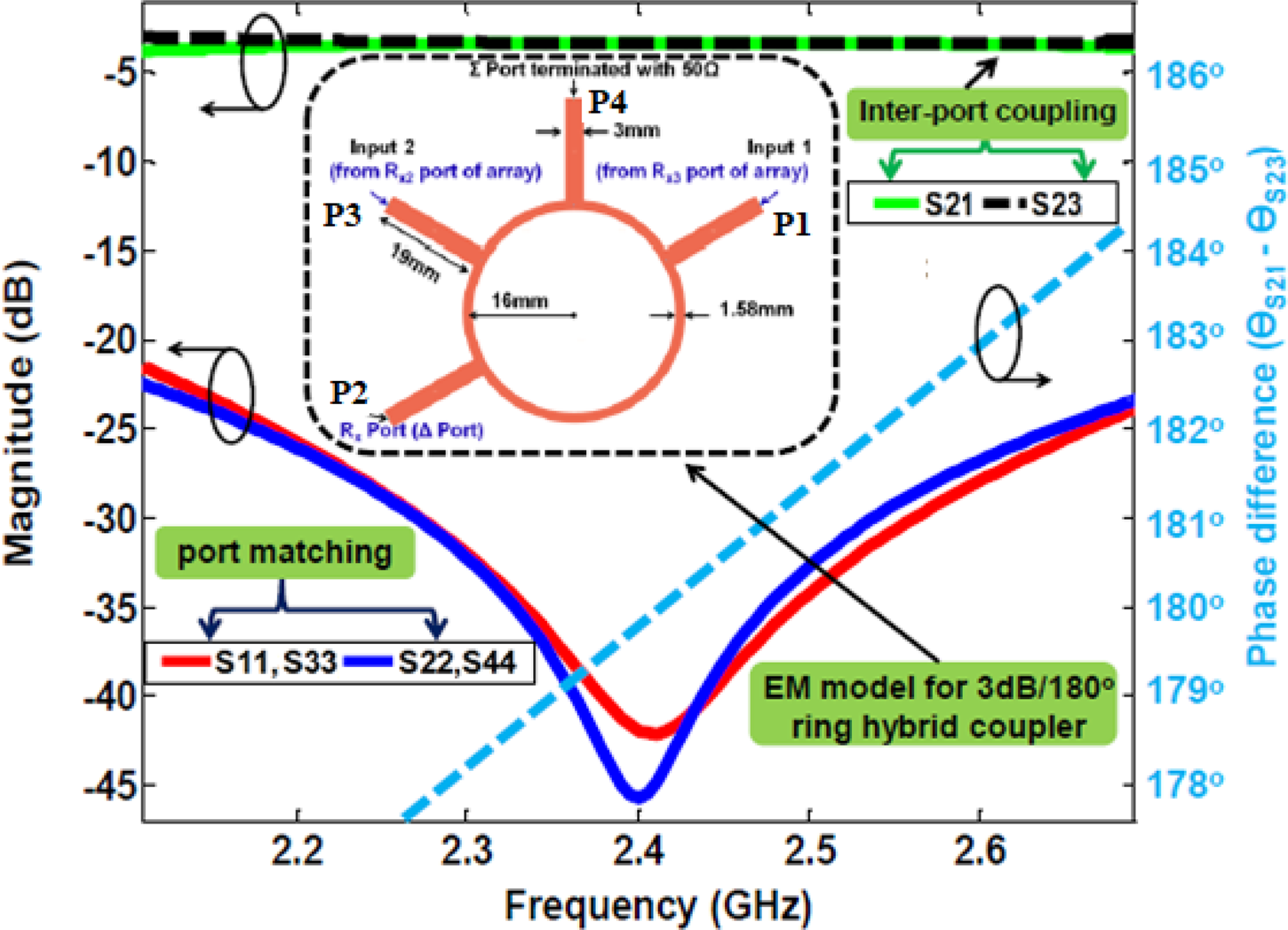
Fig. 7. EM model and simulation results for the 3 dB/180° ring hybrid coupler (SIC circuit). The coupler has been designed on a 1.6 mm thick FR-4 substrate (ɛ r = 4.4 & tanδ = 0.02).
A 2.4 GHz, 3 dB/180° ring hybrid coupler has been designed on a 1.6 mm thick general purpose FR-4 substrate (ɛr = 4.4, tanδ = 0.02) and optimized design parameters for the 2.4 GHz 3 dB/180° ring hybrid coupler are shown in Fig. 7. The simulation results for the 2.4 GHz, 3 dB/180° ring hybrid coupler are also shown in Fig. 7. The proposed 2.4 GHz 3 dB/180° ring hybrid coupler provides very nice port matching and amplitude balance characteristics as clear from Fig. 7. The simulated return-loss for each port >20 dB over the frequency range of 2.1 to 2.7 GHz. Moreover, the simulation results indicate <0.1 dB amplitude imbalance and < ± 1° phase difference for the frequency range of 2.35 to 2.45 GHz (100 MHz bandwidth). As stated earlier and shown in Fig. 5, a differential network (circuit) with these values of amplitude and phase errors will offer >35 dB SIC over 100 MHz on the top of 30–35 dB isolation (polarization diversity isolation). Hence, the total interport isolation should fall in the range of 65–70 dB over a SIC bandwidth of 100 MHz. However, the SIC levels will improve when the SIC bandwidth is reduced because of comparatively small amplitude and phase errors. Moreover we need to perform SIC in 60 MHz bandwidth only as our proposed antenna array has 10 dB return-loss bandwidth of 60 MHz (as clear from Fig. 6).
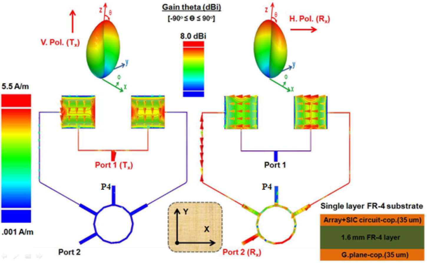
As presented in Fig. 8, the three port antenna array and 3 dB/180° power combiner are integrated to realize a compact antenna structure for a single-input single-output IBFD transceiver. This design has been realized on a single-layered 1.6 mm thick general purpose FR-4 substrate (ɛr = 4.4, tanδ = 0.02). The radiating structure (antenna elements) and differential feeding network are placed on top of the FR-4 substrate whereas the copper layer on the bottom side of the substrate will form a ground plane for the presented patch antenna array as indicated in Fig. 8. The microstrip transmission lines have been used for intended interconnections. As shown in Fig. 8 through full-wave simulated surface currents for individual excitation of Tx and Rx ports, the presented differential fed patch antenna array is linearly vertically and horizontal polarized for excitation from respective Tx and Rx ports. As clear from Fig. 8, the difference port (Δ port) of the integrated 2.4 GH, 3 dB/180° ring hybrid coupler has been used as the Rx port of the compact, dual polarized IBFD antenna array for effective SIC operation which is based on differential feeding at the Rx port as detailed earlier in section “Differential feeding based SIC scheme for 1 × 2 IBFD antenna array”.

Fig. 8. The simulated surface current distributions at 2.4 GHz frequency for the compact, differential fed, dual polarized 1 × 2 IBFD antenna array.
Measurement results for compact differential fed 1 × 2 IBFD antenna array
The proposed dual polarized, differential fed, 1 × 2 antenna array was implemented and measured in order to verify the differential feeding based SIC concept. A single-layered FR-4 substrate (ɛr = 4.4, tanδ = 0.02) having with a thickness of 1.6 mm was used for the implementation of the prototype of the proposed array. The implemented validation model for the compact (array and feeding networks on the same PCB), dual port, dual polarized, differential fed IBFD antenna array is shown in Fig. 9. The designated Tx and Rx ports and detailed dimensions for the implemented prototype of the antenna array are also shown in Fig. 9. Three SMA connectors (two for Tx and Rx ports and one for 50 Ω termination at Σ port of the ring hybrid coupler) were soldered on the back side of the PCB and connected to respective ports as shown in Fig. 9.
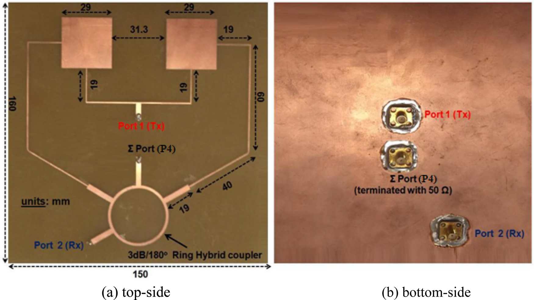
Fig. 9. The implemented prototype of the compact, dual port, dual polarized, differential fed 1 × 2 array antenna for 2.4 GHz full duplex wireless applications.
The implemented antenna array has been characterized by measuring the input reflection coefficients (S 11, S 22) and interport coupling (negative isolation). Figure 10 plots the measured and simulated impedance matching (S 11, S 22) and Tx–Rx coupling (S 21) performance results for the implemented validation model of the differential fed, dual polarized, 1 × 2 IBFD antenna array. The measured impedance bandwidth (referring to return loss ≥10 dB) for port 1 (Tx port) ≥50 MHz (from 2.39 to over 2.44 GHz) and >45 MHz (from 2.39 to 2.435 GHz) for port 2 (Rx port). Meanwhile, very high Tx–Rx isolation levels have been observed where the measured peak Tx–Rx isolation levels ~85 dB as illustrated in Fig. 10. Moreover, the measured isolation (in chamber) is over 65 dB within 50 MHz (2.39 to 2.44 GHz) and better than 75 dB in 20 MHz (2.4 to 2.42 GHz). The interport measurement results reflect a nice SIC performance through differential feeding at the Rx port.
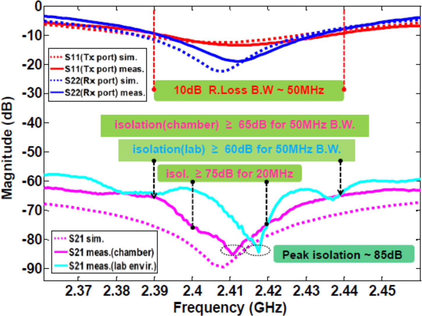
Fig. 10. The simulated and measured S-parameters (S 11, S 22, and S 21) result for the implemented prototype of the dual port, dual polarized, and differential fed IBFD antenna array.
As discussed earlier, the dual polarization provides 35–40 dB isolation between Tx and Rx signals and our proposed SIC scheme based on differential Rx operation has achieved 30–35 dB additional isolation on top of polarization diversity isolation. As clear from Fig. 10, there is nice agreement between the simulation and measurement results performed in an anechoic chamber. However, the measured isolation results show some degradations compared to simulated one, which can be attributed to fabrication accuracy. The measured isolation in a lab environment (in the presence of reflections) is >65 dB for 50 MHz bandwidth.
The measured E-plane far-field, two-dimensional (2-D) radiation patterns at 2.4 GHz frequency for the implemented prototype of the dual port, differential fed array antenna are depicted in Fig. 11. The implemented validation model of the dual polarized array characterizes >7 and >7.5 dBi gains for linear dual polarized radiations under port 1 (Tx port) and port 2 (Rx port) excitations respectively. The simulated radiation efficiency (not presented here for brevity) is around 50% only for each port excitation and gain/efficiency for the array can be improved by using low loss substrate instead of the general purpose FR-4 substrate (with tanδ = 0.02). Moreover, the measured cross-polarization levels at the boresight are lower than −35 dB (Tx port) and −45 dB (Rx port) from respective co-polarized levels as illustrated in Fig. 11. These measurement results reflect nice polarization purity characteristics for the implemented array.
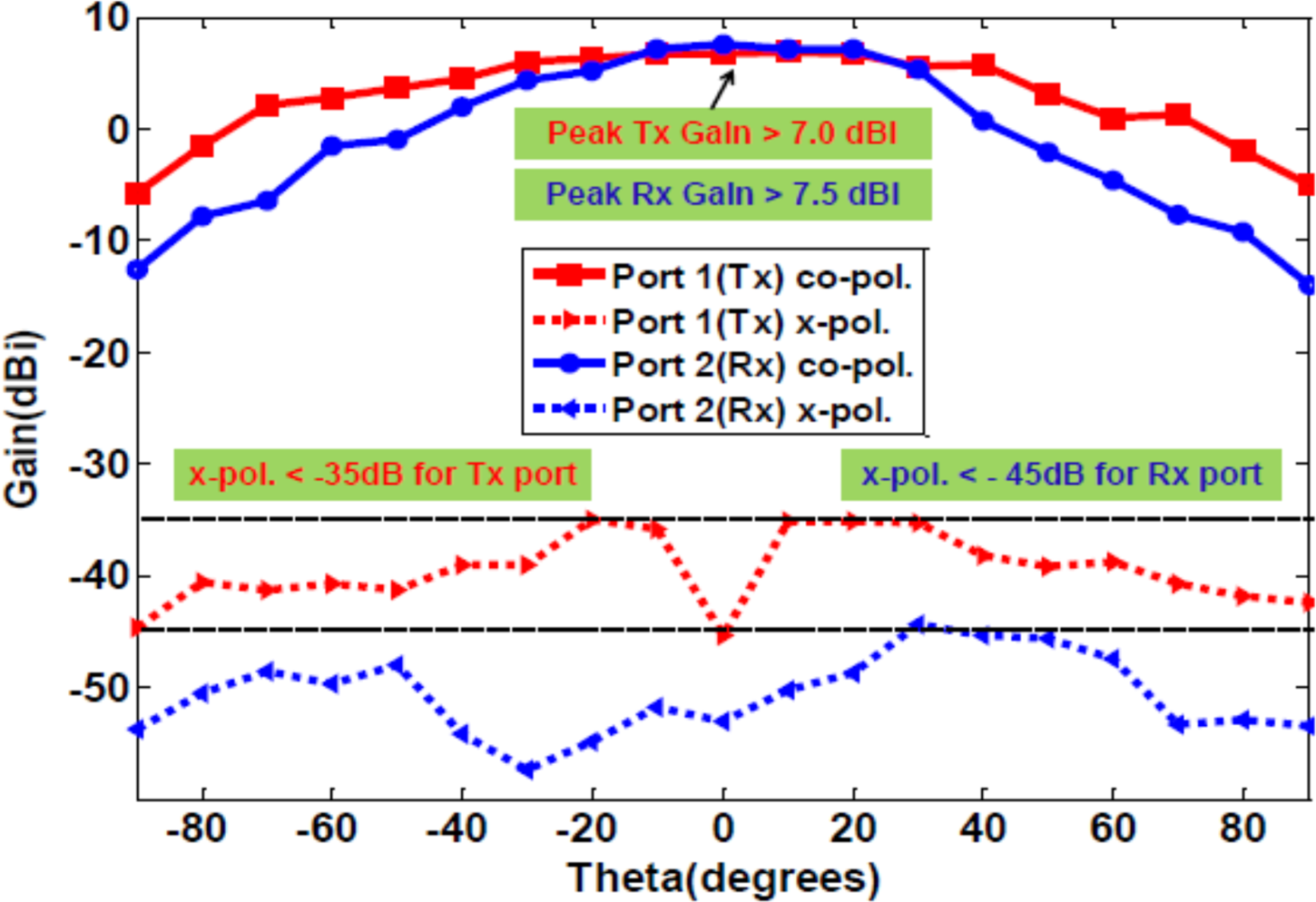
Fig. 11. The measured E-plane, 2-D far-field radiation patterns at 2.4 GHz frequency for the implemented prototype of the dual polarized, differential fed antenna array.
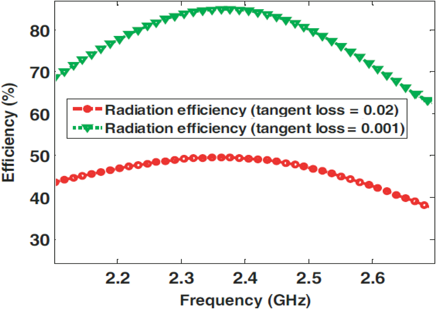
The radiation efficiency of the presented antenna is low due to high loss (loss tangent) of FR-4 dielectric used for array antenna implementation. The radiation efficiency and consequently the gain of the presented antenna array can be improved significantly by using a low loss substrate for antenna implementation. This can be endorsed through antenna array simulations with reduced value loss tangent (tanδ). For example, as reported in [Reference Nawaz and Basit35] and clear from simulation results in Fig. 12, the radiation efficiency of the antenna will be increased to more than 87% at 2.4 GHz frequency when tanδ is reduced from 0.02 to 0.001. Consequently the gain of the antenna will be doubled (3 dB additional gain in this case).

Fig. 12. The simulated radiation efficiencies of the presented antenna for tan δ = 0.02 & tan δ = 0.001 when the Rx port of the proposed antenna array is excited.
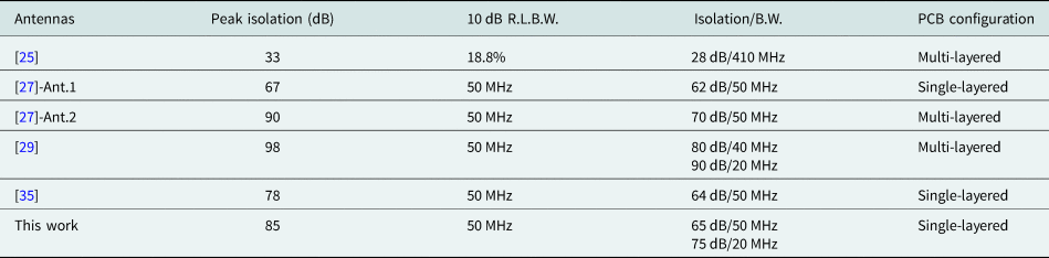
The measured results for the implemented prototype of the proposed array (especially interport isolation results) demonstrate improved performance compared to previously published works on such antennas [Reference Deng, Li, Zhang and Feng25, Reference Nawaz and Tekin27, Reference Nawaz and Tekin29, Reference Nawaz and Basit35]. These performance improvements are attributed to effective cancellation of mutual coupling and SI through a well-balanced differential feeding mechanism. The comparison of the presented antenna with previously reported 2.4 GHz antennas is detailed in Table 1. As listed in Table 1, the reported antenna array in [Reference Deng, Li, Zhang and Feng25] provides a wider bandwidth of 18.8% but the interport isolation is limited to around 28 dB for this topology. Moreover, it employs the multi-layered PCB configuration. Our previously reported antennas in [Reference Nawaz and Tekin27, Reference Nawaz and Tekin29, Reference Nawaz and Basit35] are based on differential feeding through similar ring hybrid couplers. However, these antennas are based on single radiating element where mutual coupling is not an issue and differential feeding is only intended for improved interport isolation. Moreover, the second antenna in [Reference Nawaz and Tekin27] and double differential antenna reported in [Reference Nawaz and Tekin29] require multi-layered PCB structures. Compared to previously reported antennas, the novelty of the presented antenna is single-layered antenna array architecture (reduced implementation complexity) and very high interport isolation through effective reduction and cancellation of inter-element coupling (mutual coupling) and Tx leakage at the Rx port. Compared to the single element based antenna, the array antenna configuration with comparable interport isolation performance is more useful for full duplex wireless applications as it provides more gain to extend the range or coverage for specified Tx power. However, the mutual coupling degrades the radiation performance and interport isolation of the IBFD antenna array. The presented antenna configuration resolves this issue through a well-balanced differential Rx mode operation.
Table 1. Performance comparison of the implemented antenna array with previously published works [Reference Deng, Li, Zhang and Feng25, Reference Nawaz and Tekin27, Reference Nawaz and Tekin29, Reference Nawaz and Basit35]
Conclusion
In this work, a differential fed 1 × 2 dual-polarized antenna array has been presented for 2.4 GHz IBFD applications. The differential feeding mechanism at the Rx port has been realized through a very simple 3 dB/180° ring hybrid coupler having nice amplitude and phase balance characteristics. The proposed SIC topology achieves high interport isolation through the combination of polarization diversity and differential feeding mechanism at the Rx port of the proposed antenna array. The differential mechanism also improves the antenna radiation performance with reduced SLL through reduction in mutual coupling between antenna elements for Rx operational mode. The measurement results indicate very high SIC levels for implemented prototype of the monostatic antenna array. The measured interport isolation performance ensures that the implemented prototype of the monostatic antenna array can be effectively used for 2.4 GHz IBFD wireless applications where the independence of the Tx and Rx channels corresponds to the high interport isolation. For instance, the proposed antenna array can be used for simultaneous wireless power transfer and data reception from wireless sensor devices through two independent wireless channels working at the same frequency band.
 Haq Nawaz received the B.Sc. degree in Electrical Engineering and the Master's degree in Telecommunication Engineering from the University of Engineering and Technology (UET), Taxila, Pakistan, in 2005 and 2012, respectively. He received the Ph.D. degree in Electronic Engineering from Sabanci University, Istanbul, Turkey. From January, 2017 to June, 2018, he has worked as a post-doc research fellow with Faculty of Engineering and Natural Sciences (FENS), Sabanci University, Turkey. During 2006–2009, he was with SUPARCO Pakistan as a RF Design Engineer. He served UET Taxila, Sub-campus Chakwal, Pakistan, as a Lecturer in Electronics Engineering from 2010 to 2012.
Currently, he is working as an Assistant Professor at department of Electronics Engineering, UET Taxila, Sub-campus Chakwal, Pakistan. His research interests include full duplex antenna design, RF circuits design and measurements for Radar and Satellite systems, beam-switched and phased scanning array antennas design, and indoor positioning systems design.
 Ahmad Umar Niazi received the B.Sc. degree in Electrical Engineering with specialization in Communication & Electronics from the University of Engineering & Technology (UET), Lahore, Pakistan and the Master's degree in Electrical Engineering from the University of Engineering and Technology (UET), Taxila, Pakistan, in 2001 and 2012, respectively. He is now pursuing his Ph.D. degree in Electrical Engineering from UET Taxila, Pakistan. He served at private and public sector industries/organizations from 2001 to 2006. He joined UET Taxila, Sub-campus Chakwal, Pakistan, and served as a Lecturer in Electronics Engineering from 2007 to 2012.
Since 2012, he is working as an Assistant Professor at department of Electronics Engineering, UET Taxila, Sub-campus Chakwal, Pakistan. His research interests include microwave antenna design, antennas for 5 G applications, full duplex antenna design, RF circuits design, beam-switched and phased scanning array antennas, and multi-band jamming techniques.
 Muhammad Abdul Basit received the B.S. degree in telecommunication engineering from FAST NUCES Islamabad, the M.S. degree in electrical engineering from UET Taxila, and the Ph.D. degree in communication and information engineering from the University of Electronic Science and Technology of China (UESTC), in 2016.
He has been an Assistant Professor with the Department of Electronics Engineering, UET Taxila, Sub-Campus Chakwal, since 2007. His area of specialization in the Ph.D. was antenna design. His research interests include flush mounted antenna design, dual polarized antenna design, and phased scanning array antennas.
 Furqan Shaukat is currently working as an Assistant Professor in Department of Electronics Engineering UET Taxila Sub Campus Chakwal. He completed his BSc in Electrical Engineering from UET Lahore in 2007. He received his M.Sc. and Ph.D. degrees from UET Taxila in 2011 and 2018 respectively. He has also worked as a Research Associate in University of Sheffield UK during his Ph.D. His research interests include computer vision and full duplex wireless communication.
 Muhammad Usman received the B.Sc. and M.Sc. degrees in Electrical Engineering from University of Engineering and Technology Taxila (UET Taxila) Pakistan in 2005 and 2012 respectively. He worked in Attock Refinery Ltd. (ARL) as a trainee engineer from January 2007 to January 2008. He then joined Pakistan Telecommunication Company Limited (PTCL) in March 2008 and served as a Senior Engineer till April 2013. In April 2013, he joined Department of Electronics Engineering in UET Taxila, sub-campus Chakwal as an Assistant Professor and is associated with teaching and research activities. His current research interests include Optical Communications and Optical Networks and Antenna System Design. Muhammad Usman is a member of Pakistan Engineering Council (PEC).