I. INTRODUCTION
The reconfigurable antenna has attracted much attention of both the researchers and the engineers owing to the advantages, including the frequency reuse [Reference Kim, Pan, Nikolaou, Kim, Papapolymerou and Tentzeris1], mitigating fade loss in rich multipath environment [Reference Valenzuela-Valdés, García-Fernández, Martínez-González and Sánchez-Hernández2], saving energy, and avoiding the noisy effect [Reference Chen, Row and Wong3, Reference Sulakshana and Anjaneyulu4] in the wireless communication system. The reconfigured characteristics of the antenna include the resonance frequency, the radiation pattern, and the polarization. The reconfigurable antenna was always applied in the cases where, more than one polarized modes are required. The presented reconfigurable antennas were primarily based on two electrical methods. One approach is to employ the pin diodes or the MEMS as the RF switch to regulate the radiating structure [Reference Lee and Sung5–Reference Sharma and Tripathi8], and another way is to design the reconfigurable feed structure [Reference Sulakshana and Anjaneyulu9–Reference Khidre, Lee, Yang and Elsherbeni11]. The disadvantage for both of these methods is that the antenna's structure becomes more complicated, the fabrication cost is increased for the additional direct-current (DC) bias circuit. Even in some reports such as in [Reference Soltani, Lotfi and Murch12], the lines providing the DC bias for the pin diode switches make a great impact on the radiation performance of the antenna, especially when the antenna resonates in a high frequency. The mechanical reconfiguration can be considered to be a novel approach to regulate the characteristics of the antenna [Reference Zhu, Cheung, Liu and Yuk13]. Generally, the actuator used to make the mechanical control is sophisticated and will lead to a bulky and expensive structure. But in this design, there is no additional structure, and the breach-truncated circular radiator can be naturally axial rotated. The reconfigurable antenna is capable to operate in a certain polarization mode and resonates at a frequency as the radiator taking a turn.
In this study, a novel frequency and polarization reconfigurable dual-layered microstrip antenna through mechanical axial rotating the breach-truncated metal radiator is presented. The metal radiator as well as the circular substrate is arranged closely on the top side of the square down substrate, and both symmetric breaches are cut in the metal radiator in order to make an asymmetric structure for circular polarization. Y-shaped coupling microstrip feedline with arced branch arms is placed between the substrates. The polarization and resonance frequency can be reconfigured by mechanically revolving the metal radiator along with circular substrate relative to the coupling feedline. This antenna can be operated in three different polarization modes and resonated in the frequency range from 4.70 to 5.03 GHz. In the following, the reconfigurable antenna in four different states will be investigated in detail. The proposed antenna is suitable to be applied in the mobile wireless communication system for the tri-polarization modes and frequency reconfigurable capacity, the resonance frequency of the antenna is regulated easily to the required frequency by shrinking or enlarging the size of the proposed antenna.
II. RECONFIGURABLE ANTENNA DESIGN
The three-dimensional (3D) fabrication and the optimized geometrical parameters of the proposed reconfigurable antenna are shown in Fig. 1. The entire antenna is comprised a breach-truncated circular metal radiator, a Y-shaped feedline with dual arced branch lines and ground printed on the bottom surface of the square substrate. The primary metal circular radiator etched on the top side of the circular FR4 substrate with the radius of 10 mm and the Y-shaped feedline is printed on the top surface of the square FR4 substrate with the size of 30 × 30 mm2. The thickness of both substrates is 1.6 mm. The permittivity and the loss tangent of dielectric used in this design is 4.4 and 0.02, respectively. The circular and the square substrates are closed to each other without any airspace. The top substrate was designed to be the circular for the sake of axial rotation convenience. The coupling feed structure is designed not only to enhance the impedance bandwidth, but also to take a convenient rotation.
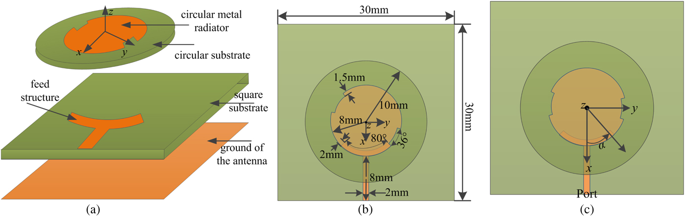
Fig. 1. (a) 3D structure. (b) The geometrical parameters. (c) Polarization/frequency reconfigurable mechanism of the proposed antenna.
III. RECONFIGURATION AND PRINCIPLE ANALYSIS
A) Reconfiguration analysis
It is assumed that the antenna is arranged on the xoy-plane in Cartesian coordinate system shown as Fig. 1(c), and the z-axis is the rotation axis for the circular upper substrate along with breach-truncated metal radiator (CSR). The CSR can be taken sequential axial rotation relative to the square substrate, arced Y-shaped feedline and the ground (SFG). The polarization and resonance frequency of the proposed antenna could be reconfigured as the SFG is taken a counterclockwise axial rotation. The axial rotation angle for the CSR relative to the SFG is denoted as α. If α is assigned to 0°, the antenna exhibits an electrical symmetrical structure shown in Fig. 1(c), and the proposed antenna operates in the linear polarization (LP) mode, the resonance frequency is 4.70 GHz. The value of α varies from 0° to 180°, and the antenna is recognized as four states as following: state one stands for 0° ≤ α ≤ 25°; state two for 25° ≤ α ≤ 50°; state three for 50° ≤ α ≤ 130° and state four for 130° ≤ α ≤ 155°. The resonance frequency and polarization mode of the proposed antenna are listed in Table 1, the simulated S 11 and axis ratio is shown in Fig. 2 when α is assigned to the different values in the different states. The antenna in last state (155° ≤ α ≤ 180°) has the symmetrical structure to that in state one, the characteristic of the antenna is also identical.

Fig. 2. Simulated S 11 and axis ratio of the proposed antenna in different states. (a) State one, (b) state three, (c) state two, (d) state two.
Table 1. Performance of the proposed antenna in different states.
Based on discussion above, it can be summarized that the antenna's polarization can be reconfigured among the LP, right-handed circular polarization (RHCP), and left-handed circular polarization (LHCP) modes in the states one, two, and four, respectively. The central operating frequency of the proposed antenna is capable to shift from 4.70 to 5.03 GHz as the state one turns to the state three. It is concluded that the both the polarization and frequency reconfigurable antenna are attained though mechanically revolving the CSR relative to the SFG. The performance of the antennas (α = 0, 40, 75, 140°) will be investigated subsequently in detail and the fabricated antennas are shown in Fig. 3.
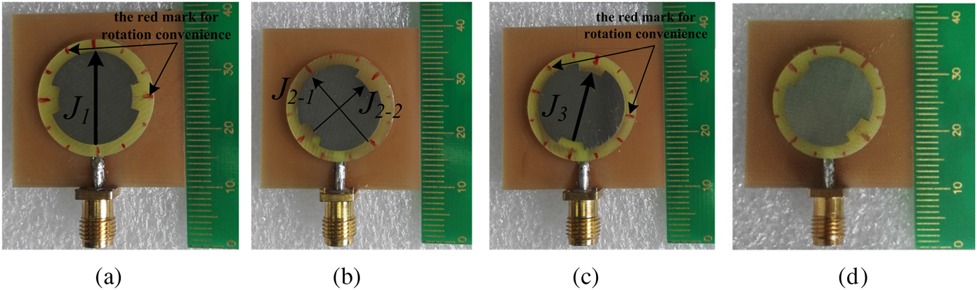
Fig. 3. Fabricated reconfigurable antenna with different values of α. (a) α = 0°, (b) α = 40°, (c) α = 75°, and (d) α = 140°.
For the rotation mechanism of the CSR relative to the SFG, a cylindroid hole with the height of 1.50 mm is fabricated at the center of the circular substrate and a column with the same height and radius to the hole can be fabricated at the center of the lower square substrate. The CSR and the SFG can be assembled together, and the column is taken as the rotation shaft for the CSR. Generally some controlling and regulating equipment is required, but in some practice the gravity can be implemented when the antenna is mounted vertically. In this design, the mechanical equipment is not supplied for the sake of the time and limited experimental environment.
B) Principle analysis
The LP polarization of this design could be explained by means of the surface current on the circular radiator. When α is equal to 0 or 75°, the structure of the antenna is symmetrical or approximate symmetrical shown in Figs 3(a) and 3(c); therefore the antenna radiates the same LP wave. The effective length of the current J 1 is L e1 = 2 × 8 mm2, but the length of J 3 is L e3 = 2 × 6.5 mm2; therefore the resonance frequency f 3 from the J 3 is higher than the frequency f 1 from J 1, which is coincident with the simulated results shown in Figs 2(a) and 2(b).
The intact circular microstrip antenna operates in the TM11 mode, generally the dual orthogonal LP degenerate modes are easily excited and they are in phase. When α is equal to 40° or 140°, the structures of antenna are asymmetrical shown in Figs 3(b) and 3(d). Dual symmetrical arced-gaps are fabricated at the edge of the circular metal patch to separate the modes and introduce a phase difference of 90° between two orthogonal linear polarized modes. It is equivalent to that dual orthogonal surface current J 2−1 and J 2−2 are excited, and they have same amplitude but a phase difference of 90° shown in Fig. 3(b).
IV. RESULTS AND DISCUSSION
The presented reconfigurable antenna has been simulated, optimized by the full-wave simulation software HFSS 13.0 and tested by Agilent PNA Series Network Analyzer E8363B and in the anechoic chamber. In the following, the performance of the proposed reconfigurable antenna at α = 0°, 40°, 75°, and 140° will be investigated in detail. In fact, the antenna with four different values of α can be considered as four different antennas, although some properties of the antennas are alike or identical.
A) S-parameters
The simulated and measured S 11 of the optimized proposed antenna at α = 0°, 40°, 75°, and 140° is depicted in the Fig. 4 and listed in Table 2. Little deviation of the central frequency between the simulated and measured results at α = 75° is from the rotation angle error of the breach-truncated metal radiator, it is a little difficult to ensure the accurate value of rotation angle α. The S 11 of the antenna at α = 40 and α = 140° is shown in Fig. 4(b). Since the structures of the antenna at α = 40 and α = 140° are mirror image of each other; therefore the S 11 is identical. The tested impedance bandwidth expands a little to the higher frequency compared with the simulated result perhaps due to the center of the upper metal radiator is deviated from the center of the square substrate when testing, and the tested port matching also becomes better. For the polarization reconfigurable antenna, the antenna is required to be operated in the same frequency band when the polarization mode is tuned. Table 2 shows that the antenna is capable to be reconfigured among the LP, RHCP, and LHCP modes in the overlapped band from 4.58 to 4.82 GHz (5.10%). It can be observed in Fig. 4(a) that the antenna is operated in the same polarization mode but the different resonance frequencies when the value of α is 0° and 75°. The antenna can be considered as the frequency reconfigurable antenna and the central frequency is tuned between 4.70 GHz (5.10%) and 5.01 GHz (5.17%).
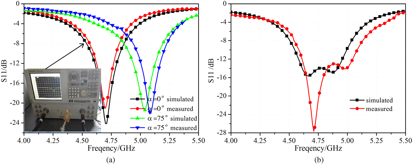
Fig. 4. S 11 of the proposed reconfigurable antenna at α = 0°, 40°, 75°, and 140°. (a) α = 0° and 75°. (b) α = 40° and 140°.
Table 2. Performance of the proposed antenna at different value of α.
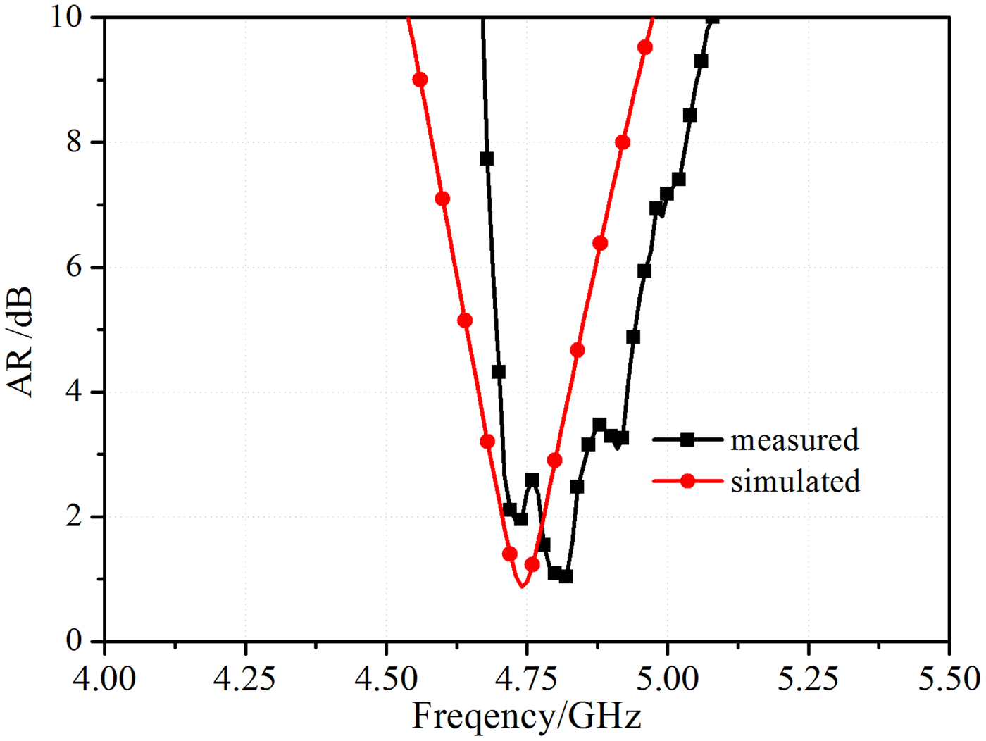
B) Axial ratio
The presented reconfigurable antenna at α = 40 and 140° is operated in the RHCP and LHCP, respectively, and the antenna depicts the identical axial ratio and most other characteristics except for the RHCP and LHCP gain in a certain plane. The axial ratio is shown in Fig. 5 and the simulated 3-dB axial ratio bandwidth is 0.12 GHz (2.53%) from 4.68 to 4.80 GHz, which is mainly agreed with the tested result. The little difference is from the fabrication tolerance, such as the air between the substrates and the rotation angle α deviates from 40° or 140°. The axial ratio of the antenna at α = 0 and 75° is unnecessary since the AR is bigger than 3 dB in the total frequency domain. In order to further illustrate the polarization mode of the antenna distinctly, the surface current distribution in different phases is offered in Figs 6 and 7 and it is clear that the antenna at α = 40° is operated in the RHCP mode and at α = 140° is in the LHCP mode. The axial ratio bandwidth of the antenna is totally covered by the overlapped impedance bandwidth discussed above, and it can be concluded that the polarization mode of the proposed antenna can be reconfigured among the LP, RHCP, and LHCP in the operating band from 4.68 to 4.80 GHz (2.53%).

Fig. 5. Axial ratio for the antenna at α = 40° and 140°.
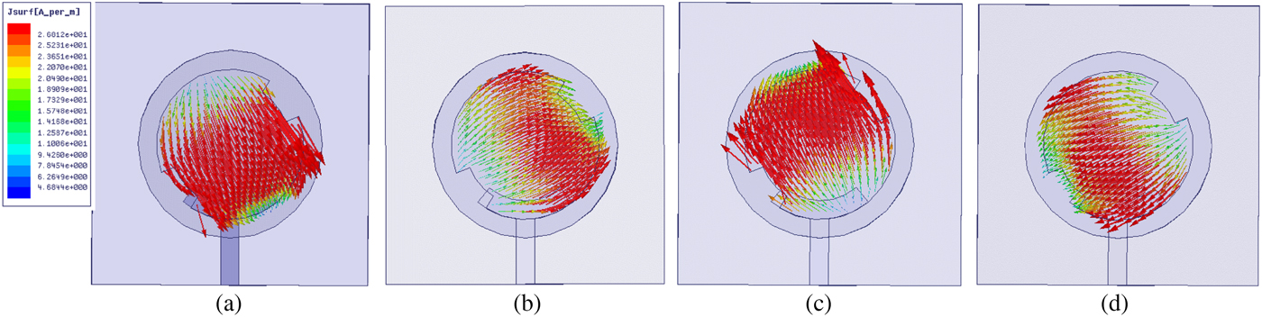
Fig. 6. Surface current distribution on the radiator at α = 40° in different phase. (a) 0°. (b) 90°. (c) 180°. (d) 270°.
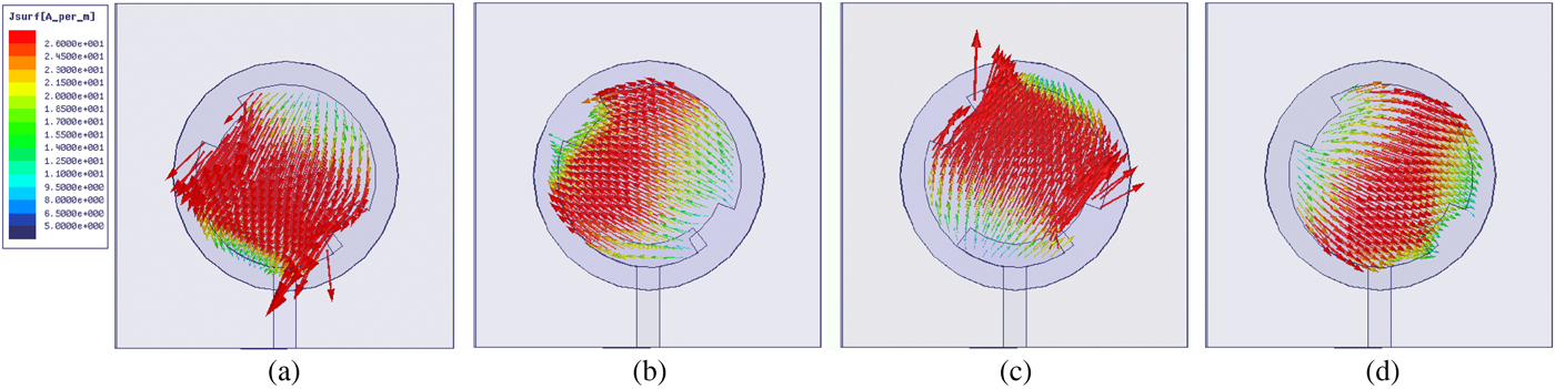
Fig. 7. Surface current distribution on the radiator at α = 140° in different phase. (a) 0°. (b) 90°. (c) 180°. (d) 270°.
C) Radiation pattern
The simulated and measured radiation patterns of the reconfigurable antenna in xoz- and yoz-planes are depicted in Fig. 8 when the α is assigned to four different values. The radiation pattern has been normalized to the same maximum value and generally the simulated and measured results agreed well with each other, little deviation is possibly from the measurement environment and fabrication tolerance. Figures 8(a) and 8(b) show radiation pattern of the antenna at α = 0° and at the frequency of 4.70 GHz, It can be seen that the antenna has a good cross-polarization isolation ratio, since the truncated mirror breaches can weaken the cross-polarization radiation. The antenna at α = 40° is operating in the RHCP mode, while the antenna at α = 140° is in the LHCP mode; furthermore their structure is mirror image. The radiation pattern shown in Figs 8(c) and 8(d) is identical with that in Figs 8(g) and 8(h), the unique difference is an exchange of the RHCP and LHCP modes. Both of them are operating in frequency of 4.75 GHz. The α turns to 75° and the radiation pattern of the antenna shows in Figs 8(e) and 8(f) at 5.03 GHz. A truncated breach is etched near the arced arm Y-shaped feed structure, and another breach is in other side of the radiator, both breaches have great impact to the cross polarization ratio. Therefore the cross-polarization radiation becomes worse compared with the antenna at α = 0° and the cross-polarization radiation gain becomes stronger.

Fig. 8. Simulated and measured radiation pattern of the proposed reconfigurable antenna at α = 0°, 40°, 75°, and 140°. (a) xoz-plane at α = 0°, f o = 4.70 GHz. (b) yoz-plane at α = 0°, f o = 4.70 GHz. (c) xoz-plane at α = 40°, f o = 4.75 GHz. (d) yoz-plane at α = 40°, f o = 4.75 GHz. (e) xoz-plane at α = 75°, f o = 5.03 GHz. (f) yoz-plane at α = 75°, f o = 5.03 GHz. (g) xoz-plane at α = 140°, f o = 4.75 GHz. (h) yoz-plane at α = 140°, f o = 4.75 GHz.
D) Gain and radiation efficiency
The measured gain and radiation efficiency of the proposed reconfigurable antenna at α = 0°, 40°, 75°, and 140° is plotted in Fig. 9, which are tested in the anechoic chamber. The proposed antenna is composed of the dual-layered substrates, which leads the more energy can be radiated. The radiation efficiency is larger than 80.6% in the overlapped band from 4.68 to 4.80 GHz (2.53%) for the polarization reconfigurable antenna. It is >80.4% in the dual bands for the frequency reconfigurable antenna. The measured gain is bigger than 2.70 dB in the overlapped band for the LP, RHCP, and LHCP modes and larger than 2.73 dB over dual bandwidth.

Fig. 9. (a) Measured gain. (b) Radiation efficiency of the proposed antenna at α = 0°, 40°, 75°, and 140°.
V. CONCLUSION
A novel frequency and polarization reconfigurable dual-layered microstrip antenna based on mechanical axial rotating the breach-truncated metal radiator is presented. The metal radiator as well as the circular substrate is closely arranged on the top side of the square substrate, and double symmetric breaches are cut in the metal radiator in order to operate in circular polarization mode. Y-shaped coupling feedline with arced branch arms is placed between the substrates and which structure is designed for the convenient rotation and bandwidth enhancement. The polarization and resonance frequency can be reconfigured respectively by mechanical revolving the radiator and circular substrates relative to the coupling feedline. The polarization of the antenna can be tuned among the LP, RHCP, and LHCP modes as α = 0°, 40°, and 140° respectively in the overlapped band from 4.68 to 4.80 GHz (2.53%), likewise, the resonance frequency of the antenna can be reconfigured between 4.70 GHz (5.10%) and 5.03 GHz (5.17%) in the same LP mode. This antenna can be considered as a novel mechanical method to realize the reconfigurable antenna with the simple structure.
 Haixiong Li was born in Shannxi Province, China, in 1982. IEEE Student Member, CIE Student Member. He received the B.Sc. degree from the School of Electrical Information Science and Engineering, Lanzhou University in Lanzhou city, China, in 2006. He received the M.Sc. degree from School of Information Science and Technology, Xiamen University in Xiamen city, China in 2013. He is presently working on his doctoral degree in School of Electronics and Information, Northwestern Polytechnical University in Xi'an city, China. His research interests include Electromagnetic Metamaterials and MIMO antenna design.
 Yunlong Gong was born in Shanxi Province, China, in 1991. He received the B.S. degree in Electrical Engineering from Xidian University in Xi'an city, China, in 2014. He works for M.S. degree in Northwestern Polytechnical University. His research interests includes reconfigurable antenna and matesurface.
 Jiakai Zhang was born in Shannxi Province, China, in 1990. He received the master degree from the School of Electronics and Information, Northwestern Polytechnical University in Xi'an city, China, in 2015. He works for doctor degree in Northwestern Polytechnical University. His research interests include: matematerials, RCS reduction of the antenna.
 Jun Ding was born in Shannxi Province, China, in 1964. She received the M.Sc. B.Sc., and Ph.D. degrees from the School of Electronics and Information, Northwestern Polytechnical University in Xi'an city, China, in 1986, 1989, and 2005, respectively. She is a Professor in the School of Electronics and Information NWPU. She has published more than 100 research papers. Her research interests include Electromagnetic Metamaterials, the Antenna theory and design, and the Microwave circuit design.
 Chenjiang Guo was born in Shannxi Province, China, in 1963. CIE Senior Member, Antenna Society Committee Member. He received the M.Sc. B.Sc., and Ph.D. degrees from the School of Electronics and Information, Northwestern Polytechnical University in Xi'an city, China, in 1984, 1987, and 2007, respectively. He is a Professor in the School of Electronics and Information NWPU. He has published more than 140 research papers. He research interests includes EMI/EMC, the antenna theory and design, and the microwave circuit design.