


I. INTRODUCTION
Multiple-input multiple-output (MIMO) antenna arrays are employed in the new generation communication systems, radars, and remote-sensing devices due to their specifications and advantages, such as reducing multipath fading, increasing transmission capacity, light weight, and ease of realization [Reference Nayan, Jamlos and Jamlos1–Reference Ko, Han and Myung5]. In the wireless telecommunication, multipath fading is an important problem when the signals with various phases and amplitudes are composed subversively in the receiver. This problem can be settled by MIMO technology. MIMO antenna arrays can be utilized to enhance the transmission capacity and reliability without an exceeding power consumption and bandwidth [Reference Li, Chu and Huang6, Reference Bhatti, Choi and Park7]. One of the significant purposes in MIMO antennas is achieving circular polarization (CP) characteristics. CP attributes provide a more flexible bilateral orientation due to independence of angle adjustment among multiple transmitters and receivers. However, CP-MIMO antenna suffers from a narrow bandwidth, relatively low gain, and loss. An array layout is utilized to improve the problems of gain and loss. The type of polarization in the element design (e.g., linear, circular, or elliptical) has a major role in the CP characteristic of MIMO antenna array [Reference Jamali, Sadeghzadeh and Naser-Moghadasi8–Reference Nasimuddin and Chen10]. It has been shown that polarization mismatch will cause to signal strength loss in some applications of MIMO antennas [Reference Zheng, Zhang, Li, Zhou and Rong11, Reference Sim12]. In the design of antenna elements, two orthogonal modes with a phase difference of 90° are excited to generate CP property. The structure is usually followed by these methods: (I) Utilization of an arc-shaped grounded metallic strip [Reference Ling and Li13]. (II) Employment of a spiral slit in the ground plane. Several techniques have been recommended for feeding a network of MIMO arrays mentioned as series [Reference Jamali, Sadeghzadeh and Naser-Moghadasi8], parallel, and corporate feeds. An SR technique has been recommended to improve radiation characteristics and CP purity [Reference Antonino-Daviu, Cabedo-Fabrés, Ferrando-Bataller and Salonen14]. In [Reference Li, Zhai, Ma, Liang, Yu and Liu15], a corporate-feeding network made of CP elements has been represented to improve 3 dB axial ratio bandwidth (ARBW), but this technique has led to the degradation of radiation characteristics. To overcome this shortcoming, an SR feeding network was utilized to enhance impedance and ARBW bandwidth over a broad frequency band. CP-MIMO antennas have attracted lots of attentions because of providing cognitive radios and next generation wireless communications, which use broadband sensing and pre-filtering at the transmitter and receiver [Reference Li, Zhang, Deng, Feng and Iskander16]. MIMO specification helps to control antenna attributes such as impedance, radiation performance, and 3 dB AR bandwidth without any significant physical changes in the scheme. It also steers left-handed circular polarization (LHCP) and right-handed circular polarization (RHCP) diversities at two ports. Antenna arrays have a low gain and poor radiation efficiency, so that different schemes have been introduced to solve these shortcomings. Unwanted surface current distributions are one of the ruinous effects on the printed circuit board (PCB) that causes excitation of unwanted modes and decline of the array performance. The techniques such as, thick low permittivity, thin high permittivity substrates, and stacked configuration ferrite composition have been introduced to defeat this imperfection [Reference Nigam and Kumar17]. Another effective approach is the defected microstrip-line structure (DMS). This structure prohibits the surface wave propagation at the specified frequency range recognized as stop-band. DMS also permits additional steering of the behaviors of electromagnetic waves at the filtering and traditional guiding structures [Reference Nigam and Kumar17]. Different layouts of DMS focused on single microstrip elements have been studied in [Reference Kazerooni and Aghalari18]. Also, it has been illustrated that when a compact DMS is utilized in a microstrip array, the array performance and impedance matching are improved. They have many applications in microwave and low millimeter wave regions, such as high-precision GPS, Bluetooth, low loss-coplanar lines, and integrated filters [Reference Kazerooni and Aghalari18].
In this paper, a precious wide-band MIMO circularly polarized antenna array for WiMAX together with C-band applications was proposed. The presented MIMO array was made of Tai Chi-shaped elements, a 2 × 4 CPMIMO-SR feed network, electromagnetic slots and slits, and microstrip structures (see Fig. 1). The Tai Chi's element was made of a pair of feeding networks and a pair of eyebrow-shaped patches (sub-elements). These sub-elements had an important role in decreasing the high cross-polarization level (HCPL) and improving gain and CP attributes. To have an extra decreasing of HCPL, a MIMO-SR feed network was employed. The spacing between the Tai Chi elements was 0.4 λ, where λ is a free-space wavelength. In the proposed CP-MIMO antenna array, two pairs of hybrid and rat-race couplers were employed at the feed network to feed four Tai Chi sub-elements in a way that each of them excited the input ports approximately 90° at the (clockwise and counterclockwise) phase difference. Based on the MIMO input performance, there were two input ports, each of which defined 1 state (state 1 for port 1 & state 2 for port 2). These states could separately control RHCP (state 1) and LHCP (state 2). A pair of vias was inserted on both sides of each Tai Chi element to improve the substrate inductance property. Also, the slot and slit structures were etched on the CP-MIMO feeding network microstrip. These structures prepared the band-reject district at the operating band of CP-MIMO antenna, thus leading to a reduced destructive mutual coupling effect. Ultimately, a prototype of CP-MIMO-SR array antenna was realized and measured to validate the design procedure and simulation results. The operating frequency band for a return loss of −10 dB was 3.5–8.2 GHz at port 1 and 3.3–8.3 GHz at port 2 that were greatly improved compared with other previous published designs [Reference Nayan, Jamlos and Jamlos1–Reference Ko, Han and Myung5] and [Reference Li, Zhai, Ma, Liang, Yu and Liu15–Reference Kazerooni and Aghalari18].
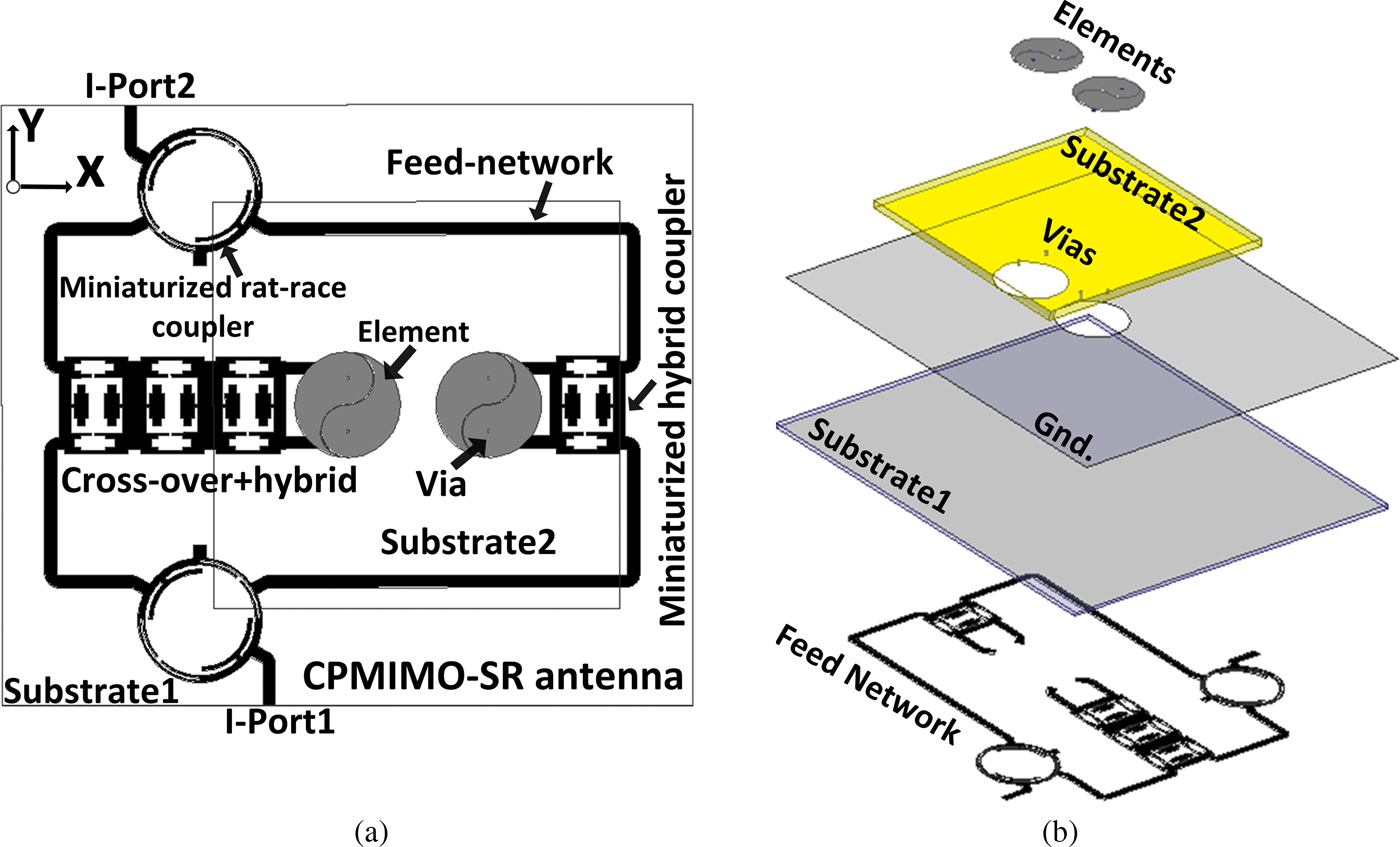
Fig. 1. (a) Configuration of presented ultimate CPMIMO-SR antenna array; (b) 3D view of prototype antenna array.
II. ANTENNA CONFIGURATION
A) Tai Chi design sub-element
The geometry of a single-array circularly polarized eyebrow-shaped sub-element is depicted in Fig. 2. As it is clear, the proposed Tai Chi's main element is made of two sub-elements. The main patch of Tai Chi element consists of two separated symmetric mirrored eyebrow-shaped patches with different feeding points to excite the resonance modes. Utilization of mirrored eyebrow-shaped patches in Tai Chi's main element causes the antenna impedance bandwidth improvement. The rectangular ground plane size was 11 × 22 mm2. The CP attribute of the sub-element was generally related to the eyebrow shapes etched on the patches. The sizes and positions of these sub-elements had important roles in steering and increasing the 3 dB ARBW. In addition, the polarization purity could be controlled by changing the distance between the feeding points and the positions of the attached strips. The proposed Tai Chi elements were fabricated on a commercially available FR4 dielectric substrate with a tiny size of 11 × 22 × 0.8 mm3, while tan δ = 0.024 and ε r = 4.4. The gap between the two separated symmetric mirrored eyebrow-shaped sub-elements was 0.2 mm. The feeding point cylinder diameter was set at 0.2 mm with an impedance characteristic of 50 Ω. The optimized dimensions of the sub-elements were R 1 = 3 mm and R 2 = 7 mm. Figure 3 shows the effect of changing the gap between the eyebrow shaped on the reflection coefficient of the element. The larger values for gap, degrades the impedance bandwidth of the element. Beside that the lower value of the gap leads to same results. Also isolation result for gap = 0.2 mm is shown in this figure.
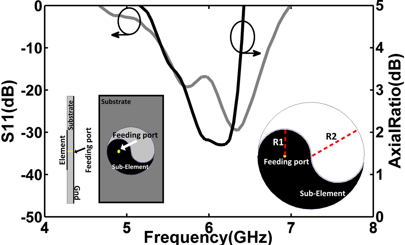
Fig. 2. Geometry of sub-element and elements with axial-ratio and impedance bandwidths

Fig. 3. Scattering parameters of the elements for different values of gap
B) CPMIMO sequentially rotated (SR) feed network scheme
The CPMIMO-SR antenna feed network was made of a pair of broadband rat-race couplers of 180°, a pair of broadband hybrid branch–line couplers, and one microwave broadband cross-over. They were linked together to form a network with four output and two inputs ports (see Fig. 4). In the proposed scheme, all the lines were designed with a characteristic impedance of 50 Ω. The antenna CP attribute was improved by CPMIMO-SR feeding network. In the following, the steps to configure the CPMIMO feeding network design are introduced:
-
Step (I): At the input ports (I-port 1, I-port 2), a broadband rat-race is used to produce two separate signals with a phase difference of 180° from the input signal.
-
Step (II): The signals received as the inputs of each broadband hybrid coupler are split into signals with equal amplitudes and a 90° phase difference.
-
Step (III): At the outputs of the broadband hybrid couplers, a broadband cross-over is applied to control the output ports and isolate the remaining feed network. By properly exciting the operational states in each input port (Fig. 4), the RHCP and LHCP orientations are obtained. RHCP is obtained in state 1 (port 1) and LHCP is acquired in state 2 (port 2).
With this configuration of microstrip components, all the MIMO-SR antenna array elements were excited with equal amplitudes and a 90° phase difference with respect to each other. This technique led to the 3 dB AR enhancement. The RHCP and LHCP steering was investigated at two states:
-
(a) State 1 (input excitation at port 1): All the elements were excited with a clockwise 90° phase difference caused RHCP generation.
-
(b) State 2 (input excitation at port 2): All the elements were fed with a counterclockwise 90° phase difference caused LHCP obtainment.

Fig. 4. Geometry of introduced CPMIMO-SR Feeding network
Moreover, 2 pairs of vias were inculcated to the sub-element patches at CPMIMO-SR feeding network for the effective transmission of signals. The dimensions of the realized prototype CPMIMO-SR feed network are shown in millimeter in Fig. 4: L 1 = 15, L 2 = 10, L 3 = 44, L 4 = 7, W 1 = 1.5, W g = 73, and L g = 85.
C) Quasi self-complementary defected microstrip structure (DMS) design
Overlapping of near-fields and the presence of surface waves in the radiating elements caused to an increase in the mutual coupling that notably reduced the antenna performance. A quasi-self-complementary DMS was presented to provide a solution to the leaky waves and surface obstacles since they had outstanding specifications, such as band rejection for surface waves and reflection coefficients for mutual incident waves [Reference Nigam and Kumar17]. A quasi-self-complementary DMS can improve antenna characteristics such as, gain and far-field radiation patterns and reduce the back lobe levels. Quasi-self-complementary DMS layouts also allow extra steering operation of incident waves in a different technique from filtering method [Reference Kazerooni and Aghalari18]. To evaluate its specification and define the band-gap regions, its layouts were inserted and etched on the CPMIMO-SR feeding network (see Fig. 4). The quasi-self-complementary DMS was realized on FR4 epoxy substrate with a thickness of 0.8 mm. The existence of the quasi-self-complementary DMS among CPMIMO-SR caused a decreased magnitude of S 21 at a range of 4.5–7 GHz and propagation cancelation of surface waves. Its unit-cell dimensions are shown in millimeter in Fig. 4: L 5 = 5, L 6 = 2, and L 7 = 10. The scattering parameters of feed network with DMS and without DMS are plotted in Fig. 5. It is deduced from this figure DMS has major role in feed network scattering parameters enhancement.

Fig. 5. Scattering parameters of feed network with DMS and without DMS
The four phases to achieve a 2 × 4CPMIMO-SR antenna array with a quasi-self-complementary DMS attribute are as follows:
-
1. Designing the CP eyebrow-shaped sub-element;
-
2. Executing the CPMIMO-SR feeding network for controlling RHCP and LHCP without a major modification of the physical design of the array;
-
3. Designing and optimizing the quasi-self-complementary DMS and its characteristics in the array;
-
4. Composing the schemes in the integrated circuit to figure the final unique CPMIMO-SR antenna array.
III. MEASURED RESULTS
The proposed CPMIMO-SR antenna array was fabricated and measured to approve the design procedure. The measured results were performed for two CPMIMO-SR antennas (Ant. 1: CPMIMO-SR antenna array without quasi-self-complementary DMS; Ant. 2: antenna array with quasi-self-complementary DMS). The measured S-parameters were accomplished by Agilent™ vector Network Analyzer 8722ES. The extracted impedance bandwidths for both arrays at the two input ports are demonstrated in Figs 6 and 7. Figure 6 shows the impedance bandwidth for the input of port 1. It is depicted that the operating bandwidths for antennas 1 and 2 range from 3.1 to 7.9 GHz and 3.5 to 8.2 GHz, respectively. At port 2, the inputs for antennas 1 and 2 are 4.1–8 GHz and 3.5–8.3 GHz, respectively (Fig. 7). It is clear that the operating bandwidth of Ant. 2 completely covers WiMAX (IEEE 802.16) and C-band, which are broader than AR and the impedance bandwidths reported in [Reference Nayan, Jamlos and Jamlos1–Reference Ko, Han and Myung5]. The measured results of ARBWs for Ant. 1 and Ant. 2 at the two input ports (1 & 2) are displayed in Figs 8 and 9. Figure 8 indicates the ARBWs at the input of port 1. It describes that the 3 dB ARBWs for antennas 1 and 2 are from 4.9 to 7.3 GHz and 4.6 to 7.6 GHz, respectively. Figure 9 depicts ARBWs for the inputs of port 2, which range from 5 to 7.3 GHz and 4.6 to 7.5 GHz for Ant. 1 and 2, respectively. The minimum point of AR curve happens at 6.7 GHz with amplitude of 0.5 dB. It can be understood that ARBW for port 2 is narrower than for port 1. This is due to the clockwise rotation of sub-elements in the ultimate antenna design. A relatively good agreement was achieved between the measurement and simulation results for both CPMIMO-SR antenna arrays. The discordances in the results were related to the non-ideal SMA connection for both input ports and the substrate dispersion loss. It is comprehended from these figures that quasi-self-complementary DMS has a major role in the antenna characteristics. To clarify the behavior of the CP characteristics from the surface current, the current vectors on the sub-element rotate counter-clockwise and clockwise with four different phases in RHCP and LHCP respectively as seen in Fig. 10. The simulated and measured gain curves for Ant. 1 and 2 for the input ports are exhibited in Figs 11 and 12. The measured peak gains of Ant. 1 are 8.2 dBi (input port 1) and 7 dBi (input port 2). The peak gains of Ant. 2 are 10 dBi (input port 1) and 9.8 dBi (input port 2). Also, the images of the fabricated CPMIMO-SR antenna array are shown in these figures. Figure 13 illustrates radiation efficiency of the MIMO antenna. It is observed that the radiation efficiency for antenna is relatively high in C band. Figure 14 shows the simulated and measured S 21 of Ant. 2. It is observed that a good isolation has been achieved between the two ports of the antenna, especially at C band. The simulated and measured normalized radiation patterns at 6 GHz for Ant. 2 are shown in Fig. 15. LHCP and RHCP were obtained at φ = 0° and 90°. Figures 15(a) and 15(b) demonstrate the normalized radiation patterns for port 1 and Figs 15(c) and 15 (d) depict the radiation patterns for port 2. The antenna has a size of 85 × 73 × 0.8 mm3. The proposed array presents a remarkable improvement in terms of 3 dB AR and impedance bandwidths. By utilizing the polarization diversity, a high isolation of 28 dB was experimentally achieved at 5.5 GHz (see Fig. 14). The envelop correlation coefficient [Reference Mao and Chu2] is calculated by the following formula:
 $$\rho = \displaystyle{{ \vert S_{11}^* S_{21} + S_{12}^* S_{22} \vert ^2} \over {(1 - \vert S_{11} \vert ^2 - \vert S_{21} \vert ^2)(1 - \vert S_{22} \vert ^2 - \vert S_{12} \vert ^2)}}.$$

Fig. 6. Simulated and measured results of return loss for antennas at I-port1.

Fig. 7. Simulated and measured results of return loss for antennas at I-port2

Fig. 8. Simulated and measured results of axial ratio for port1.

Fig. 9. Simulated and measured results of axial ratio for port2.

Fig. 10. Distribution of the vector surface current on the proposed sub-element at 5.5 GHz in: (a) RHCP 0°, 90°, 180°, 270° phase; (b) LHCP0°, 90°, 180°, 270° phase
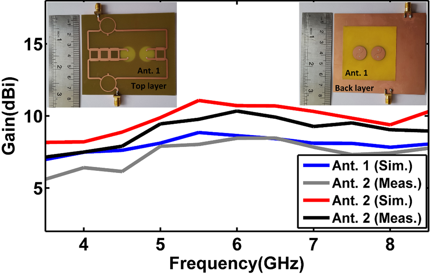
Fig. 11. Measured gains of both antennas as versus of frequency for port1.

Fig. 12. Measured gains of both antennas as versus of frequency for port2.

Fig. 13. Radiation efficiency of the MIMO antenna

Fig. 14. Simulated and measured S 21 parameter of Ant. 2

Fig. 15. Extracted far field results at 6 GHz for Ant. 2: (a, b) RHCP (I-port1) and (c,d) LHCP (I-port2).
At 5.5 GHz, the envelope correlation was computed from the measured scattering parameters to be 0.00061. Since this quantity was minor, it was verified that the proposed array was suitable for a MIMO wireless communication application. The diversity gains and correlation coefficients were nearly correlated as shown by equation (2). The lower the correlation value was, the better the diversity gain, G app was achieved [Reference Nayan, Jamlos and Jamlos1].
 $$G_{app} = 10 \times \sqrt {1 - \vert \rho \vert \;}. $$
Correlation coefficient of ultimate CPMIMO-SR antenna is illustrated in Fig. 16 and The diversity gain of the proposed array could be stated as the best quality result as depicted in Fig. 17. It was obvious that for the two uncorrelated arrays and accepted bit error of 1%, the diversity gain was 9.8 dB. A comparison between the proposed antenna array and the antenna arrays presented in previous researches has been shown in Table 1. It is observed that the proposed antenna array has a good performance and radiation characteristics.

Fig. 16. Correlation coefficient of ultimate CPMIMO-SR antenna

Fig. 17. Diversity gain of ultimate CPMIMO-SR antenna.
Table 1. Comparison of the performances and characteristics between the proposed antenna array and antenna arrays in the previous works.

IV. CONCLUSION
A broad-band CP-MIMO antenna array with an improved CP purity, impedance matching bandwidth, and radiation performance was proposed. Using proper MIMO sequential rotation techniques, axial ratio, and impedance tuning bandwidths were efficiently enhanced. Specific forms of slots were utilized in the array layout to reduce the mutual coupling between the elements and surface wave destructive effects. A high isolation between two elements and ports were obtained by defecting the network microstrip line and introducing broadband microwave components. It was understood that utilization of slot and stub structures on the feed network improved the overall characteristics of MIMO-SR antenna. The MIMO-SR antenna had two individual ports for two different operational CPs (RHCP & LHCP) that could be separately controlled based on each port excitation. The ultimate CPMIMO-SR antenna array had an impedance bandwidth ranging from 3.5 to 8.2 GHz at port 1 and 3.5 to 8.3 GHz at port 2 for S 11 ≤ −10 dB. Also, it had a 3 dB ARBW, which extended between 4.6 and 7.6 GHz. The measured maximum gain was 10 dBi at 6 GHz. Finally, the realized antenna proposed a number of outstanding specifications, including efficient polarization purity, broad impedance matching, less cross-polarization level, low undesirable radiation from the feeding points, comparatively good gain, and size reduction, which made it as the most advantageous choice for the new generation wideband wireless communications.
ACKNOWLEDGEMENT
The authors would like to thank Professor Bal Virdee and Dr. T. Sedghi for their valuable discussions and suggestions.
 Mahdi Jalali received the B.S. degree in Electronic Engineering from IAU, Urmia Branch, Urmia, Iran, in 2003. He received M.S. degree in Electrical Engineering in Islamic Azad University south Tehran Branch, Tehran, Iran, in 2006. Now he is a Ph.D. student in IAU Science Research Branch, Tehran, Iran. His research interests include antennas, circular polarization, radar application, and intelligent computing. He has published more than 30 papers in his referred international journal and national/international conferences.
 Mohammad Naser-Moghadasi was born in Saveh, Iran, in 1959. He received the B.Sc. degree in Communication Engineering in 1985 from the Leeds Metropolitan University (formerly Leeds Polytechnic), UK. Between 1985 and 1987 he worked as an RF design engineer for the Gigatech Company in Newcastle Upon Tyne, UK. From 1987 to 1989, he was awarded a full scholarship by the Leeds educational authority to pursue an M.Phil., studying in CAD of Microwave circuits. He received his Ph.D. in 1993, from the University of Bradford, UK. He was offered then a 2 years Post Doc. To pursue research on Microwave cooking of materials at the University of Nottingham, UK. From 1995, Dr. Naser-Moghadasi joined Islamic Azad University, Science & Research Branch, Iran, where currently he is an Associate Professor and head of postgraduate studies. His main areas of interest in research are Microstrip antenna, Microwave passive and active circuits, RF MEMS. Dr. Naser-Moghadasi is member of the Institution of Engineering and Technology, MIET and the Institute of Electronics, Information and Communication Engineers (IEICE). He is the member of editorial board at International Journal of RF and Microwave Computer-Aided Engineering John Wiley and Son's publication. He has so far published over 140 papers in different journals and conferences.
 Ramazan Ali Sadeghzadeh received the B.Sc. degree in Telecommunication Engineering from K. N. Toosi University of Technology, Tehran, Iran, in 1984; the M.Sc. degree in Digital Communication Engineering from the University of Bradford, Bradford, U.K., and the University of Manchester Institute of Science and Technology (UMIST), Manchester, U.K., as a joint program in 1987, and the Ph.D. degree in electromagnetic and antenna from the University of Bradford in 1991. During 1992 to 1997, he worked as a Postdoctoral Research Assistant in the field of propagation, electromagnetic, antenna, biomedical, and wireless communication with the University of Bradford. From 1984 to 1985, he was with Iran Telecommunication Company, Tehran, Iran, working on networking. Since 1997, he has been with the Faculty of Electrical and Computer Engineering, K. N. Toosi University of Technology. He has published more than 120 referable papers in international journals and conferences. His research interests include numerical techniques in electromagnetics, antenna, propagation, radio networks, wireless communications, nano antennas, and radar systems.


