


Introduction
Healthcare sector has revolutionized drastically in recent times especially in the field of medical body area networks (MBAN). Due to diverse areas of applications including sports, medicine, defense, and wearable computing, a considerable research has witnessed huge progress over the last decade [Reference Hall and Hao1]. The application of smart systems to monitor and diagnose patient's conditions in real time has resulted in reducing the patient's inconvenience a lot. An antenna is an integral part of the MBAN system which decides the efficiency of the overall transmission system. The antenna serves the purpose of not only collecting information from other body-worn sensor devices, also it transmits the information to the nearby base station [Reference Lin, Li, Ito, Takahashi and Saito2]. Here, a different mode of operation requires multiple polarizations, respectively. An omnidirectional beam with vertical polarization is optimal for ON body communications whereas horizontal polarization with unidirectional broadside beam is favorable for OFF body communications. The requirements for ON body communication recommend the appropriateness of vertical monopole type antennas. But at lower industrial, scientific and medical (ISM) band frequencies in view of the overall profile, a conventional monopole antenna is not appropriate for ON body applications [Reference Werner and Jiang3]. Some of the techniques adopted for the design of antennas for ON body communication includes: microstrip patch antennas with higher order modes [Reference Conway and Scanlon4], a circular patch antenna with TM 21 mode [Reference Tak, Lee and Choi5], circular ring patch antenna with TM 31 mode [Reference Tak and Choi6], and cavity slot antenna [Reference Haga, Saito, Takahashi and Ito7]. The higher order modes of the above antennas provide comparable performance with respect to monopole antennas. However, considering the specific radiation pattern requirement for each mode of operation, they are not suitable for OFF body communication as they radiate horizontally omnidirectional pattern only. Design of antenna for MBAN applications has to be considered from the perspective of various requirements like the level of impedance detuning due to the lossy human body [Reference Kellomaki8], miniaturization, polarization mismatch losses [Reference Nechayev, Wu, Constantinou and Hall9], specific absorption rate (SAR) limitations [10], low profile and lightweight. Considering the coupling between the lossy human body and antenna, a planar inverted F- antenna (PIFA) is considered as a suitable candidate for wearable applications due to its full ground plane structure [Reference Soh, Vandenbosch, Ooi and Rais11]. Wearable PIFA was first introduced in the year 1999 for operation at 2.45 GHz [Reference Salonen, Sydanheimo, Keskilammi and Kivikoski12]. Since then a number of researches with wearable PIFA antennas considering single band [Reference Lin, Saito, Takahashi and Ito13, Reference Gil and Garcia14], multi-band [Reference Lin, Li, Ito, Takahashi and Saito15–Reference Boyes, Soh, Huang, Vandenbosch and Khiabani17], broadband [Reference Soh, Vandenbosch, Ooi and Rais18] operations were reported. Again for all the PIFA antennas reported above, single polarization characteristics were discussed only. Dual-mode dual-band antennas with a patch like radiation pattern for OFF body communication and monopole type radiation pattern for ON body communication were recently reported in [Reference Hong, Tak and Choi19, Reference Tak, Woo, Kwon and Choi20]. In the above two cases, dual mode is realized using two radiators where each radiator radiates in separate bands. The application of two or more radiators for generating separate modes increases the overall profile of the antenna.
In this work, a dual band dual polarized PIFA antenna is proposed for ON/OFF body communication at 2.5 and 3.5 GHz bands. The equivalent offset fed magnetic microstrip type dipole antenna has been utilized to generate the omnidirectional radiation pattern at lower band whereas the slotted patch counterpart is responsible for generating the broadside radiation beam at higher band. As a result of this, dual band dual mode antenna has been realized using a single radiator only. The shorting wall width and height are found to be crucial in controlling the frequency ratio between the two bands respectively. A single, as well as multi-layer tissue model, has been employed to study the performance of the antenna under ON body conditions. The antenna is found to be suitable for on-body operation considering its compactness, easy-to-fabricate structure, lightweight, and robust on-body performance.
Antenna structure and design
Considering the easy market availability, foam with relative permittivity (ε r) of 1.14 and thickness of 9 mm has been chosen as a suitable substrate due to its lightweight, heat and moisture resistant and easy mount ability properties over the human body. Further, lower permittivity and higher thickness substrates are sometimes more suitable where higher bandwidth requirements is a pre-requisite [Reference Brebels, Ryckaert, Come, Donnay, De Raedt, Beyne and Mertens21]. Bandwidth efficiency product can be quite enhanced with a large volume of the antenna. The footprint of the antenna is only 40 × 20 mm2.
Coaxial feeding technique has been used for laboratory purpose and testing only. In real-life applications, mini SMA connector can be employed which assures flat garment in-layer. Also, on-body circuitry components located at the backside of the antenna can be used to feed the antenna [Reference Xiaomu, Yan and Vandenbosch22].
The conducting material is made up of copper tape of thickness 0.076 mm. The radiator part has been fabricated using a single piece of the copper sheet without any interconnections using glue or soldering. This method provides a constant surface conductivity of the radiator. The schematic diagram of the proposed antenna is shown in Fig. 1. A Parasitic small square patch is connected with the bigger truncated patch through a strip line. The truncations in the designed antenna are found to be helpful in mitigating frequency shift when it is loaded over the human body. The asymmetric square structure can be used for generation of dual-band antennas. But with this technique, different polarization structures cannot be realized within the same radiator. The main objective here is to design dual-band antenna having dual polarization property.

Fig. 1. Schematic diagram of the proposed antenna design.
Material characterization
Electromagnetic characterization of the material to be used as substrate should be analyzed at the chosen frequency band in order to achieve the preferred functionality of the wearable antenna. The dielectric properties of the substrate to be used for the wearable antenna are measured using Agilent Dielectric Measurement probe kit as shown in Fig. 2.
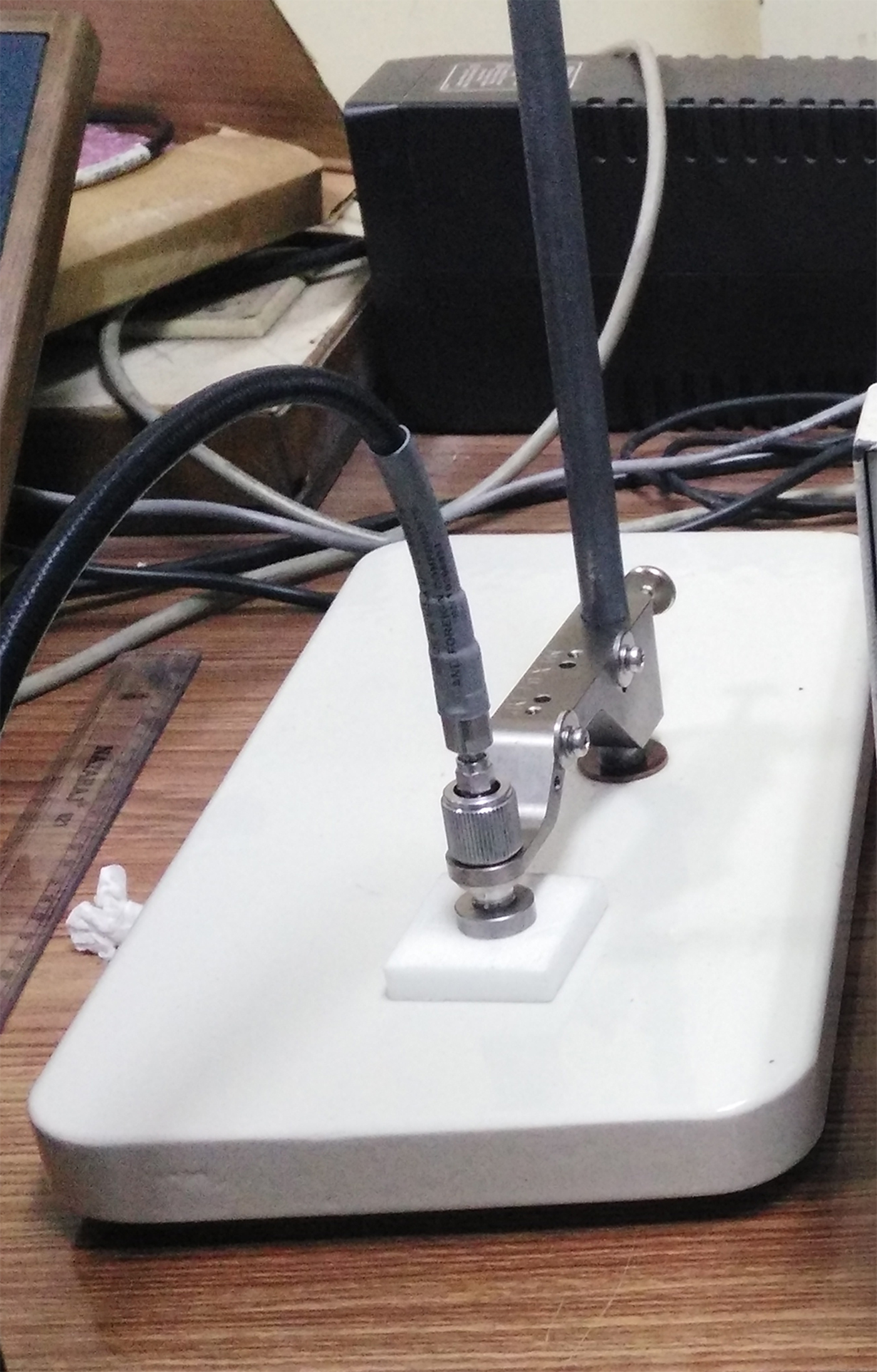
Fig. 2. Dielectric parameters measurement.
In order to obtain accurate results, repeatability of the measurement is performed with multi-layers and dielectric properties like permittivity and loss tangent are measured. The results of the measurement are given in Table 1.
Table 1. Measured dielectric parameters of the substrate.

Characteristics and analysis
The designed PIFA antenna is divided into two sections: (1) equivalent magnetic microstrip dipole section, (2) slotted section as shown in Fig. 3. Magnetic microstrip dipole consists of a patch and ground element with one side fully or partially shorted [Reference Kaloi23]. Offset fed magnetic microstrip dipole is employed where the feed position is varied along the edge to obtain an optimum impedance matching. The resonant frequency of the partially shorted patch antenna has been calculated using the formula given in [Reference Kumar and Ray24]:
 $$f_{\rm 0}= \displaystyle{\hbox{3} \over {\hbox{4}[L{\rm + (}W{\rm -} w_s{\rm )/2}]\sqrt {\varepsilon _e}}}, $$
where L, W, w s, ε e are the effective length, width of the RMSA, width of the shorted portion, and effective dielectric constant of the substrate.

Fig. 3. Equivalent model of the PIFA.
From Equation (1), it can be observed that with the reduction in the value of w s, the value of f o shifts left and vice versa. In the proposed design, we have used a partially shorted patch antenna. A partially shorted patch antenna shows more miniaturization over fully shorted one. The design methodology of the antenna is discussed herein. The evolution of the design is shown in Figs 4(a)–4(e). After the design of the 1st ref. PIFA antenna, the width of the patch has been extended fully which has been referred to as Ref. 2 antenna. The resonant frequency of the shorted patch antenna mainly depends upon the dimensions of the shorting wall and width of the patch, so increasing the length of the patch barely affects its resonant frequency. In the 3rd step, two slots have been cut near to the middle of the patch which is referred as Ref. 3 antenna. From the S 11 curve, it can be observed that another mode generates along with the shorted patch mode but impedance matching is poor in this case. In this case, the modes are adjacent to each other. In order to control the frequency ratio between the two modes, the asymmetrical patch has been employed which is referred to as Ref. 4 antenna. The generation of two modes can be observed in the S 11 curve. These are the steps employed during optimization of the antenna in free space. As a final step, the antenna has been optimized on the phantom model by cutting truncation in both the patches referred as Ref. 5 which resulted into required frequency shift in the lower band and improved matching respectively.

Fig. 4. Evolution of the design (a) Ref. antenna 1, (b) Ref. antenna 2, (c) Ref. antenna 3, (d) Ref. antenna 4, (e) proposed design, (f) S 11 variation for different reference antennas.
The surface current distribution over the antenna is shown in Figs 5(a)–5(b) at a frequency of 2.5 and 3.5 GHz. It indicates that the maximum current is distributed vertically over the shorting wall at a lower frequency. Thus, in this case, the aperture part is excited effectively which resulted in monopole-like omnidirectional field of the antenna. At the higher frequency, maximum surface current flows near to slotted section of the patch surface that resulted in broadside radiation pattern. Thus effective excitation of both these counterparts resulted in a generation of specific radiation patterns which could support ON/OFF body communication.

Fig. 5. Simulation results of surface current distribution at (a) 2.5 GHz, (b) 3.5 GHz.
Parametric study
A set of parametric studies is performed in order to achieve the maximum impedance matching and desired range for the frequency of interest. The simulations were performed in Finite element Method-based solver ANSOFT high-frequency structure simulator. During analysis when a single parameter is varied, the others are kept constant unless specified. The next section provides details about different parameters which were considered during parametric analysis of the designed antenna. To avoid complexities during simulations on account of limited resources, single layer phantom model has been employed for parametric analysis. However, during final design, multilayer phantom model has been employed to actuate more human body conditions.
Effect of side wall width
The shorting wall connecting the ground and the patch is varied stepwise in this analysis. From Figs 6 (a)–6(b) it can be inferred that improved impedance matching for the 1st band is obtained when the side wall width (t) is reduced.

Fig. 6. Simulated results for (a) S 11 variation with side wall width, (b) Re (Z in) variation with side wall width.
But reducing the side wall also moves the lower frequency band to the left side while the higher band is unaffected. This is in accordance, that a partially shorted wall would show more miniaturization over fully shorted one. The real part of the impedance increases beyond 2.6 GHz with reducing the side wall width while below 2.6 GHz, the real part of the impedance goes closer to the 50 Ω region which signifies improved matching at smaller values of side wall width as shown in Fig. 6(b).
Effect of patch dimensions variation
The PIFA antenna is constituted of bigger and smaller patch connected through stripline. In this section, the effect of varying dimensions of both smaller and bigger patch is studied. It can be observed from Fig. 7(a) that reducing the width of the bigger patch affects the lower resonant frequency and it shifts right. The effective current path length increases with increasing bigger patch dimensions. The higher resonating frequency shifts left but in this case, the rate of change is small. Reducing the width of the smaller patch reduces the slot length thereby the resonant frequency of higher band shifts right whereas the matching of the 1st band deteriorates with reducing width as shown in Fig. 7(b).

Fig. 7. Simulated results for (a) S 11 variation with bigger patch width, (b) S 11 variation with smaller patch width.
Effect of strip width and length
The case study for stripline width (s) variation is performed for input impedance (Z 11) and S 11 values. The results of the analysis are shown in Figs 8(a)–8(b).

Fig. 8. Simulated results for (a) impedance variation with strip width, (b) S 11 variation with strip length.
Increasing the strip width reduces the real part of the impedance of the 1st band while that of 2nd band increases. The imaginary part of the impedance of 1st band is more sensitive with strip width variation over the 2nd band. Thus increasing the strip width improves the impedance matching of the 1st band more effectively over the 2nd one. Also increasing the strip width increases the current path length around the slotted section thereby shifting higher band to the left as shown in Fig. 8(b).
Effect of sidewall height
The effect of sidewall height is studied in this analysis. During the simulations, the side wall width (t) and strip width (s) are kept unvaried. The results are shown in Fig. 9. The side wall height has a significant effect on the resonating frequency of the first band which gets shifted to the left side with an increase in height. The frequency ratio between two bands can be controlled with variation in sidewall height. It can be observed that the slope of the 1st resonant frequency is steeper over the 2nd resonant frequency which means the 2nd band is minimally affected. Considering the desired frequency range i.e. 2.5 and 3.5 GHz, the finest height can be within the region 9–10 mm where the two curves intersect as shown in the figure. Accordingly, the optimized height of the substrate is taken to be 9 mm for coverage of the two bands.

Fig. 9. Simulated results for frequency ratio and height variation.
Effect of ground plane variation
The variation in dimensions of the ground plane on the performance of the PIFA antenna is studied in this section. The ground plane length seriously affects the higher resonating frequency when its length goes below the overall patch size as in the case of g l = 30 mm where the resonant frequency shifts right drastically. Otherwise, the variation in the resonant frequency occurs but still it covers the designated bands as shown in Fig. 10(a). The ground plane width variation affects the lower band whereas the higher band is not found to be much affected as shown in Fig. 10(b).

Fig. 10. Simulated results for (a) S 11 variation with ground plane length, (b) S 11 variation with ground plane width.
Effect of truncation variation on single patch
When the single antenna (referred as Ref. antenna 1) with truncations is employed, it can be observed that with an increase in truncations, the real part of the impedance reduces and the resonant frequency shifts right as shown in Figs 11(a)–11(b). This small tuning mechanism would be used for mitigating the frequency shift when the antenna is placed over a phantom.
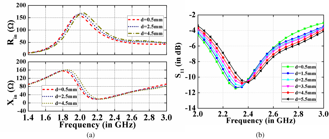
Fig. 11. Simulated results for (a) impedance variation with truncation length, (b) S 11 variation with truncation length.
Simulated and experimental results
On the basis of the parametric analysis, the optimized dimensions of the antenna were derived and the prototype of the antenna is fabricated. The optimized dimension of the antenna as shown in Fig. 1 is given in Table 2.
Table 2. Optimized dimensions of the antenna.

The antenna is simulated using a single layer skin phantom model as well as three-layer phantom models. The phantom has overall dimensions of 70 × 70 × 31 mm3. It consists of skin, fat, and muscle layers as shown in Fig. 13(a), respectively. The dielectric properties were obtained from [Reference Andreuccetti, Fossi and Petrucci25]. The dielectric properties of different tissues at 2.5 and 3.5 GHz are given in Tables 3 and 4.
Table 3. Dielectric properties of different tissues at 2.5 GHz.

Table 4. Dielectric properties of different tissues at 3.5 GHz.

Initially, the antenna has been designed under free space conditions with the specific dimensions (without truncations) but when the antenna has been placed over the phantom model certain extent of detuning takes place and the resonant frequency shifts left. The 4 G long term evolution (LTE) band is not covered in this case (2.5–2.69 GHz).
In that scenario, the truncated cut at the corner can be used as discussed earlier for frequency tuning. The truncated cut shifts the resonant frequency to the right thereby covering the required band, respectively. The result of the analysis is given in Table 5.
Table 5. Resonating frequency variation with truncation length.

The fabricated antenna is shown in Figs 12(a)–12(b). For ON body analysis, the antenna is placed at a height of 3 mm over the phantom model to mimic the real-life scenario where the antenna would be placed overgarments. The practical model of the antenna placed over skin equivalent phantom with 3 mm spacers beneath is shown in Fig. 12(c). The skin equivalent phantom has been prepared according to the recipes mentioned in [Reference Karacolak, Hood and Topsakal26] and thereby the permittivity values were measured using a dielectric measurement probe kit.

Fig. 12. Fabricated antenna (a) top view, (b) side view, (c) antenna placed over skin phantom model.
To test the robustness of the antenna under different tissue environments, single skin layer, as well as multi-layer tissue model comprising skin, fat, and muscle, has been employed as shown in Fig. 13(a). The simulated reflection coefficient result is shown in Fig. 13(b) for a different number of tissue layers.

Fig. 13. (a) Simulation set up of the antenna over 3-layer phantom model. (b) Simulated reflection coefficient of the designed antenna on different phantom models.
It can be observed that the variation of dielectric properties of the phantom model does not have too much detuning effect on the antenna resonant frequencies. Though the impedance matching of the higher band is affected, still the antenna is able to cover the desired bands of operation.
In order to analyze the antenna for practical body-centric communications, the propagation properties need to be analyzed. For OFF body and ON body measurement, set up of the antenna is shown in Fig. 14 along the line of sight. The chest is the flattest part of the body. Since the antenna is not bendable due to foam substrate so the appropriate location of the antenna to be placed is chosen as the chest which also actuates simulation set up with the measurement one. The chosen location assures immunity to bending effects, respectively.

Fig. 14. Measured S 11 and S 21 results.
The S 11 and S 21 parameters of the fabricated antenna are measured using Anritsu vector network analyzer. The measured S 11 result covers the desired band of 2.5 and 3.5 GHz effectively as shown in Fig. 14. The measured −10 dB S 11 bandwidth ranges from 2.37 to 2.67 GHz for the 1st band whereas for the 2nd band it is from 3.3 to 3.72 GHz. A little mismatch of S 11 parameters is due to the fabrication tolerance on account of the manual cutting process. From the transmission losses curve, it can be observed that at lower band the S 21 values for ON body communication is around −45 dB. This signifies a reliable and efficient link for ON body communication at 2.5 GHz band. In case of transmission loss values for OFF body communication, the S 21 values are well below around −40 dB at higher frequency band. This indicates the suitability of the antenna for OFF body communication at higher frequency, respectively.
Simulated radiation patterns at 2.5 and 3.5 GHz in both free space and phantom model are plotted in Figs 15(a)–15(d). At 2.5 GHz, an almost omnidirectional pattern in the horizontal plane with a null along the broadside is achieved. In the upper band, a broadside pattern is obtained and the back lobes have been reduced in tissue model due to the reflection and absorption on the lossy phantom respectively. A good separation between cross and co-pol. components were obtained along conical and broadside direction in both 2.5 and 3.5 GHz bands.

Fig. 15. Simulated radiation patterns at 2.5 GHz (a) XZ-plane, (b) XY-plane 3.5 GHz, (c) XZ-plane, (d) YZ-lane.
Figures 16(a)–16(b) shows the peak gain and radiation efficiency results in free space and on the phantom model. Two types of skin equivalent phantoms, one designed at 2.45 GHz and other phantom designed at 3.5 GHz frequency [Reference Andreuccetti, Fossi and Petrucci25] were employed for the experimental purpose. The peak gains in free space are 0.3 and 4 dB at lower and upper bands. And when the antenna is placed on the phantom, the peak gains are 0.26 and 1.75 dB, respectively. It can be observed from Fig. 16(a) that more reduction in gain is observed at higher frequency owing to the higher back radiation at 3.5 GHz whereas the gain variation for the lower band is not so much high as the back radiation is lower in this case. The peak efficiencies at both lower and higher bands are 67% and 58%, which are high enough for MBAN applications, respectively.

Fig. 16. Measured results (a) peak gain, (b) S 11 and radiation efficiency.
In order to find the biological effect of the antenna over the human body, local SAR value is considered on the skin layer model and simulated results are plotted in Figs 17(a)–17(b) at 2.5 and 3.5 GHz, respectively. SAR refers to the amount of power that human tissues absorb when exposed to RF radiation. IEEE C95.1–2005 restricts the SAR limit to 1.6 W/Kg when averaged over 1gm tissue [10]. Initially, calculation of the SAR values over 1 gm tissue is performed using 30 dBm as input power. In that case, SAR value is found to be higher than the IEEE C95.1-2005 limits. Consequently, the maximum input power has been reduced to 25.78 and 20.3 dBm for the 1st and 2nd band in order to limit the maximum SAR values.
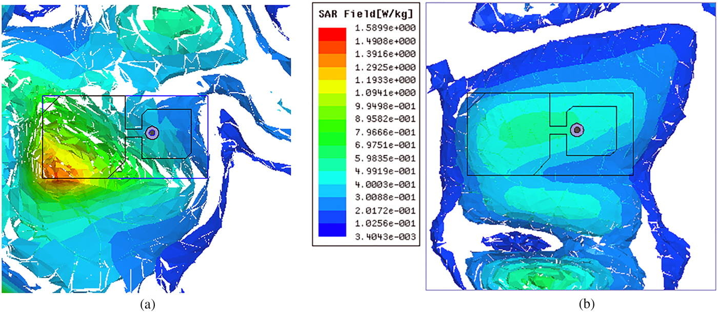
Fig. 17. Simulated SAR results at (a) 2.5 GHz, (b) 3.5 GHz.
Finally, the designed antenna is comprehensively compared with other state of art reported wearable antennas. The comparative study is shown in Table 6. From the results, it is observed that the proposed antenna has a merit in terms of dual band dual polarization property supporting ON/ OFF body communication along with acceptable gain and bandwidth. From the table, it can be found that previously reported wearable PIFA antennas were suitable either for ON or OFF body communication but not both at the same time.
Table 6. Performance comparison for the proposed antenna with other reference PIFA antennas.

Conclusion
A dual band dual polarized PIFA antenna is proposed for ON/OFF body communications. The designed antenna covers the ISM, 4 G LTE, Wi-Fi, and WLAN bands efficiently with a maximum gain of 0.1 and 4.4 dB in each band. To test the robustness of the antenna, single layer, as well as multi-layer tissue model, has been employed. The omnidirectional property at 2.45 GHz supports the ON body communication whereas the broadside radiation pattern at 3.5 GHz is feasible for OFF body communication. Considering the compactness, light weight, robustness, and dual-band property, the antenna is found to be a potential candidate for real-world MBAN applications.
Acknowledgement
The authors would like to acknowledge the Ministry of Electronics and Information Technology (MEITY), Ministry of Communication & IT, Government of India for providing financial assistance during research work and Jadavpur University for measurement facilities.
 Shankar Bhattacharjee was born in Assam, India. He received B. Tech in Electronics and Communication engineering from the West Bengal University of Technology, India, in 2013 and M. Tech from National Institute of Technology (NIT), Arunachal Pradesh, in 2015. Since 2015, he is pursuing the Ph.D. degree in Microwave engineering at the Department of Electronics and Telecommunication Engineering, Indian Institute of Engineering Science and Technology (IIEST), Shibpur, West Bengal, India. His research interests include design and optimization of antennas for wearable and implantable applications.
 Manas Midya received his B.Tech. degree in Electronics and Communication Engineering from Jalpaiguri Govt. Engineering College, West Bengal, India in 2009 and M.E. degree in Microwave Communication from Indian Institute of Engineering Science and Technology (IIEST), Shibpur, Howrah, India in 2014. His research interest includes designing of circularly polarized antennas. He has contributed to numerous research articles in various journals and conferences of repute. He is currently working towards the Ph.D. degree at IIEST, Shibpur.
 Monojit Mitra did his B.Tech, M.Tech, and Ph.D. from the Institute of Radio Physics & Electronics under Calcutta University in the year of 1982, 1984–1985, and 1995, respectively. Then he joined as an Assistant Professor in the Department of Electronics & Telecommunication Engineering of IIEST (Formerly B. E. College), Shibpur in 1995 and at present, he is a Professor there. He had served as a head from 2012 to 2014 and also he is again serving the department as a head from 2016 to till date. His research area of interest is in the field of Microwave and especially in the fabrication of IMPATT diodes and systems. He had written five books as on “Satellite Communication”, “Microwave Semiconductor Devices”, “Microwave Engineering”, “Electronic Circuits” and “Microwave Measurements”. Ten students had completed their Ph.D. work under his supervision and eight are continuing. He had published more than 80 research papers in different national and international journals. He is also a member of different prestigious societies. He is also the recipient of many prestigious awards.
 Sekhar Ranjan Bhadra Chaudhuri received the B.E. and M.E. degrees in electronics and telecommunication engineering from the Bengal Engineering College, University of Calcutta, Kolkata, India, and the Ph.D. (Engineering) degree from Jadavpur University, Kolkata, in 1990. He is currently a Professor with the Department of Electronics and Telecommunication Engineering, Indian Institute of Engineering Science and Technology (IIEST), Shibpur (formerly Bengal Engineering and Science University, Shibpur), India, where he has been for more than 36 years. He is a Reviewer of John Wiley, IET, Francis and Taylor, SPRINGER, and PIER journals. He has supervised 12 doctoral students. He is the joint inventor of two Indian Patents (Product and Process as well). He has authored or co-authored more than 150 research papers in various international/ national journals and conferences. During 2013–2017, he was associated with the Indian Space Research Organization sponsored collaborative project with the Indian Institute of Technology Kharagpur entitled “Studies on Retro-directive Arrays for Space Applications” as the Principal Investigator at IIEST and completed the same successfully. His research interests mainly include small antennas for mobile communication and electromagnetics for advanced applications. He is a Life Member of the Indian Society for Technical Education and the Electromagnetic Interference/Electromagnetic Compatibility Society of India.


