Introduction
Super-wideband (SWB) antennas are designed in this paper according to the FCC and IEEE protocols for various types of wireless systems. The FCC 02-48 report efficiently regulated Ultra-Wideband (UWB) systems in 2002 [1]. The fractalization technique has been used to achieve very broad bandwidths and also miniaturization of antennas [Reference Azari, Ismail, Sali and Hashim2–Reference Waladi, Mohammadi, Zehforoosh, Habashi and Nourinia8]. Due to the broad bandwidths of such antennas, appropriate techniques need to be developed for impedance matching to improve their Voltage Standing Wave Ratio (VSWR) performance. Some researchers have been carried out work to form the shape of ground planes to obtain broad bandwidth impedance matching, such as semielliptical ground planes [Reference Waladi, Mohammadi, Zehforoosh, Habashi and Nourinia8] and ridged ground plane [Reference Thakare and Rajkumar9]. Several studies [Reference Lin and Chuang10, Reference Ojaroudi, Ghobadi and Nourinia11] use various types of slots in the ground planes for impedance matching. UWB systems, due to their wide bandwidth, can have interference effects on other systems, such as WiMAX (Worldwide Interoperability for Microwave Access-3.3–3.7 GHz), WLAN (Wireless Local Area Network-5.15–5.825 GHz), and X-band satellite communication (7.9–8.4 GHz). In order to avoid frequency interference, band rejection techniques should be adopted at these bands for UWB antennas [Reference Yuanfan12, Reference Jaglan, Gupta, Kanaujia, Srivastava and Thakur13].
In this paper, an extremely broad bandwidth and compact antenna is proposed using triangular fractal patches and semi-elliptical ground plane with removal of square pieces from the top of elliptic ground plane under the transmission line. To create two rejection bands, one rectangular split-ring resonator (SRR) is used at the bottom side located at the top of the elliptical plane for WiMAX band rejection [Reference Numan and Sharawi14] and a U-shaped slot is cut in the transmission line feed for WLAN band rejection. In the following, the fractal antenna is first studied without the band rejections and then the effects of SRR and U-slot are investigated separately. Their performances for the creation of desired rejection bands are studied.
Antenna configuration
Figure 1 shows the antenna views from the top and bottom sides. The proposed antenna is designed on the substrate FR4 with 1 mm standard thickness and 4.4 dielectric constant with a 21 mm × 23.5 mm compact patch. This antenna includes one microstrip transmission line and one circular patch. Triangular shape slots in the form of fractal geometry are formed in the circular patch. Figure 2 shows the steps of fractalization of circular microstrip patch antenna. The antenna size decreases from 30 mm × 30 mm × 1.6 mm to 23.5 mm × 21 mm × 1 mm. The use of oval-shaped ground plane at the bottom side and the rectangular gap at its end create very good impedance matching for the fractal antenna. On the microstrip transmission line feed a U-shaped slot is cut for the removal of WLAN interfering frequency band 5.1–5.85 GHz (Fig. 1(c)). Also to create the WiMAX band rejection with a frequency of 3.4–3.7 GHz, a rectangular SRR is made at the bottom side above the oval ground plane (Fig. 1(b)).
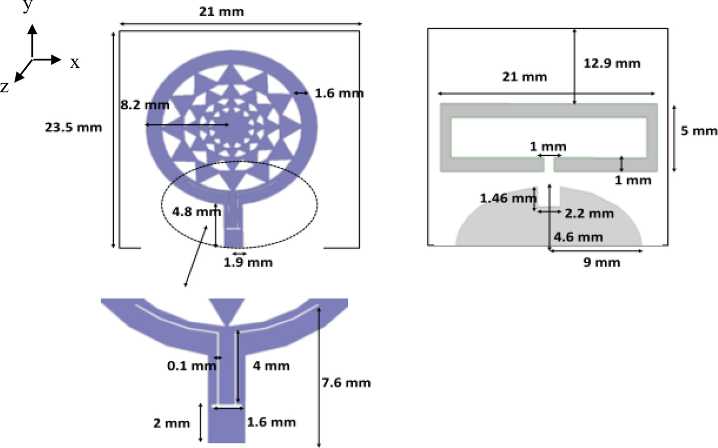
Fig. 1. Geometry of the proposed antenna: (a) top side; (b) bottom side; and (c) microstrip feed line.

Fig. 2. Fractalization steps of circular microstrip patch antenna.
Design and simulation
The proposed antenna is simulated for different values of parameters. The frequency responses of antenna are obtained as its parametric studies, such as VSWR, gain, and radiation pattern. Figure 3 shows the VSWR of antenna without the rectangular SRR and U-slot, and also shows that the VSWR of antenna in the whole frequency range of 3–40 GHz is less than 2 (for S11, it is less than −10 dB).

Fig. 3. Frequency response of fractal antenna: (a) VSWR and (b) S_11 (dB).
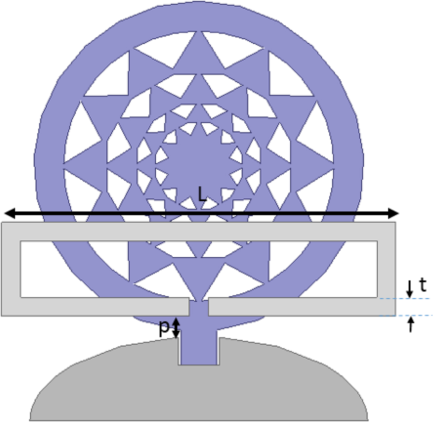
Figure 4 shows the antenna geometry with the rectangular SRR (used to create a WiMAX rejection band in 3.4–3.7 GHz for the level of 3 dB). Only three parameters are varied including length of rectangular split ring (L), width (t), and the distance from the oval ground plane (p) (see Fig. 4). The frequency responses of antenna (S_11) are shown in Figs 5(a)–5(c). Figure 5(a) shows that varying the length of the rectangular SRR changes the central frequency of the rejection band. Figure 5(b) shows that varying the distance of the SRR from the oval ground plane could control the depth of the rejection band (that must be better than −3 dB). Figure 5(c) shows that varying the width of the SRR could control the bandwidth and partially the central frequency of the rejection band. The geometrical dimensions and characteristics of SRR may be obtained, which exactly achieve the FCC standard for WiMAX band rejection (in the 3.4–3.7 GHz frequency) and without any changes in the antenna bandwidth.

Fig. 4. Variable parameters of rectangular SRR.

Fig. 5. Variation of simulated frequency response of antenna (S_11) as a function of parameters: (a) length of SRR; (b) distance from the oval ground plane; and (c) line width.
Figure 6 shows the antenna geometry with a U-slot cut in the microstrip feed line. For investigating the effect of U-slot on the frequency response of antenna, the SRR is first neglected. Figure. 7 shows that the center frequency of the rejected band is decreased upon increasing the total length of half ring on the microstrip feed line. However, the maximum length of simple U-slot on the microstrip feed line (in Fig. 7) could shift the center frequency of rejected band to a minimum frequency of about 11 GHz. It can't reach the center frequency of WLAN band, namely 5.5 GHz. But this technique could be used for removing another interfering band, such as the X band. Due to the small size of microstrip feed line, there is no way of increasing the total horizontal or vertical lengths of U-slot. However, half of the circumference of ring could be increased for rejecting the WLAN band. We use a new and unprecedented improved method to reduce the center frequency. We increase the semicircle radius. Optimization of the geometrical dimensions would reach the center frequency of 5.5 GHz by removing the WLAN frequency band of 5.1–5.85 GHz.
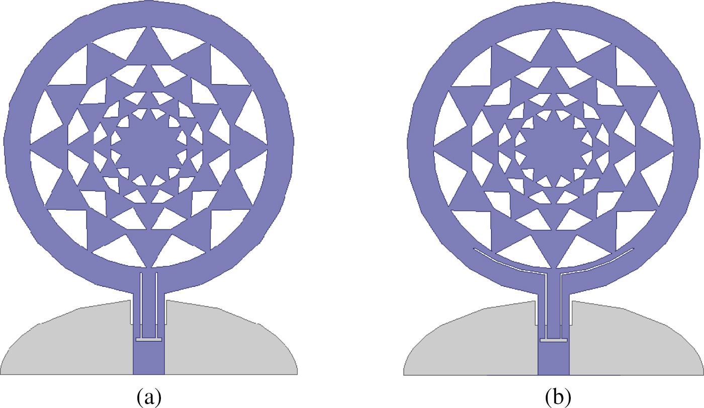
Fig. 6. Geometry of the proposed antenna: (a) simple U-slot and (b) enhanced U-slot.

Fig. 7. Variation of simulated frequency response (VSWR) of antenna after cutting the U-slot on microstrip feed line: (a) VSWR and (b) S_11 (dB).
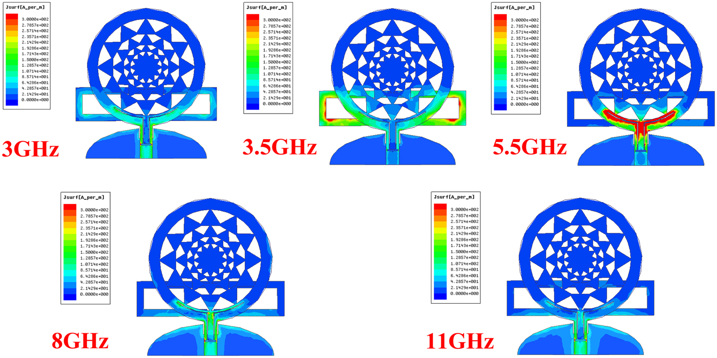
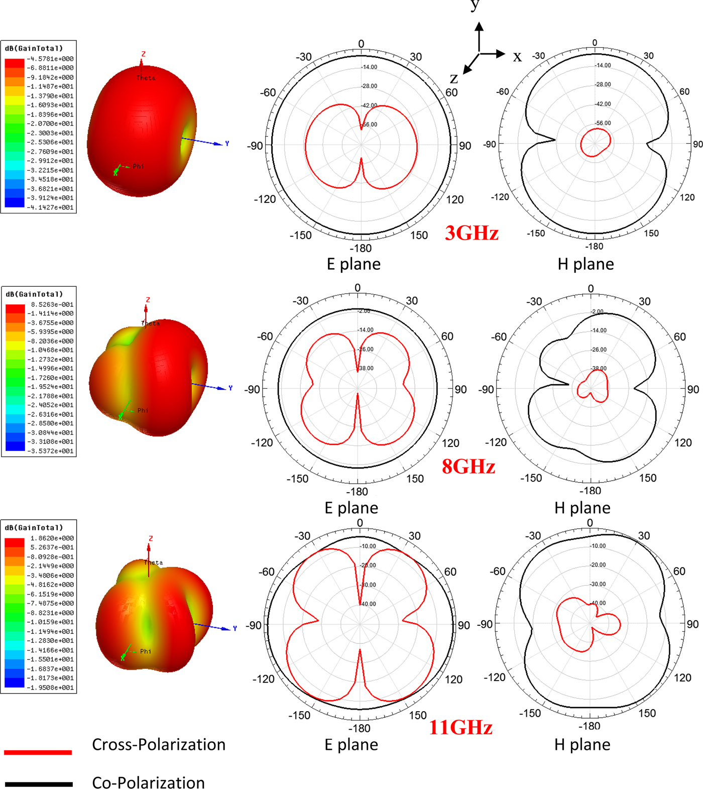
The antenna structure with the SRR and enhanced U-slot is optimized for its best characteristics. Its optimum dimensions are shown in Fig. 1. The simulated results of VSWR and reflection coefficient S_11 of fractal antenna in Fig. 1 are shown in Figs 8(a) and 8(b). The simulated surface currents at frequencies 3, 8, and 11 GHz and also notch frequencies (3.5 and 5.5 GHz) are shown in Fig. 9. From the figure, it can be observed that at 3.5 GHz frequency the surface current on the SRR and at 5.5 GHz the surface current around the slot are much denser and prevent the antenna to radiate at these notch frequencies. The simulated radiation patterns for three frequencies of 3, 8, and 11 GHz are shown in Fig. 10. The E-plane and H-plane radiation patterns and 3D patterns are depicted, and also observe that the cross-polarization levels are higher at higher frequencies.

Fig. 8. Simulated frequency response of antenna: (a) VSWR and (b) reflected coefficient S_11 (dB).

Fig. 9. Simulated surface currents at frequencies 3, 3.5, 5.5, 8, and 11 GHz.

Fig. 10. Simulated radiation patterns of antenna: (a) 3, (b) 8, and (c) 11 GHz.
Figure 11 shows the peak gain of antenna versus frequency, which increases at higher frequencies up to a maximum of 7 dB.
Fig. 11. Simulated peak gain of antenna.
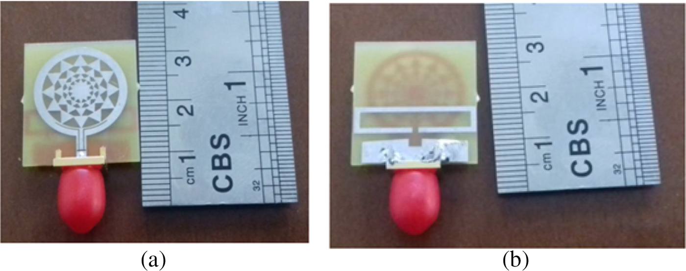
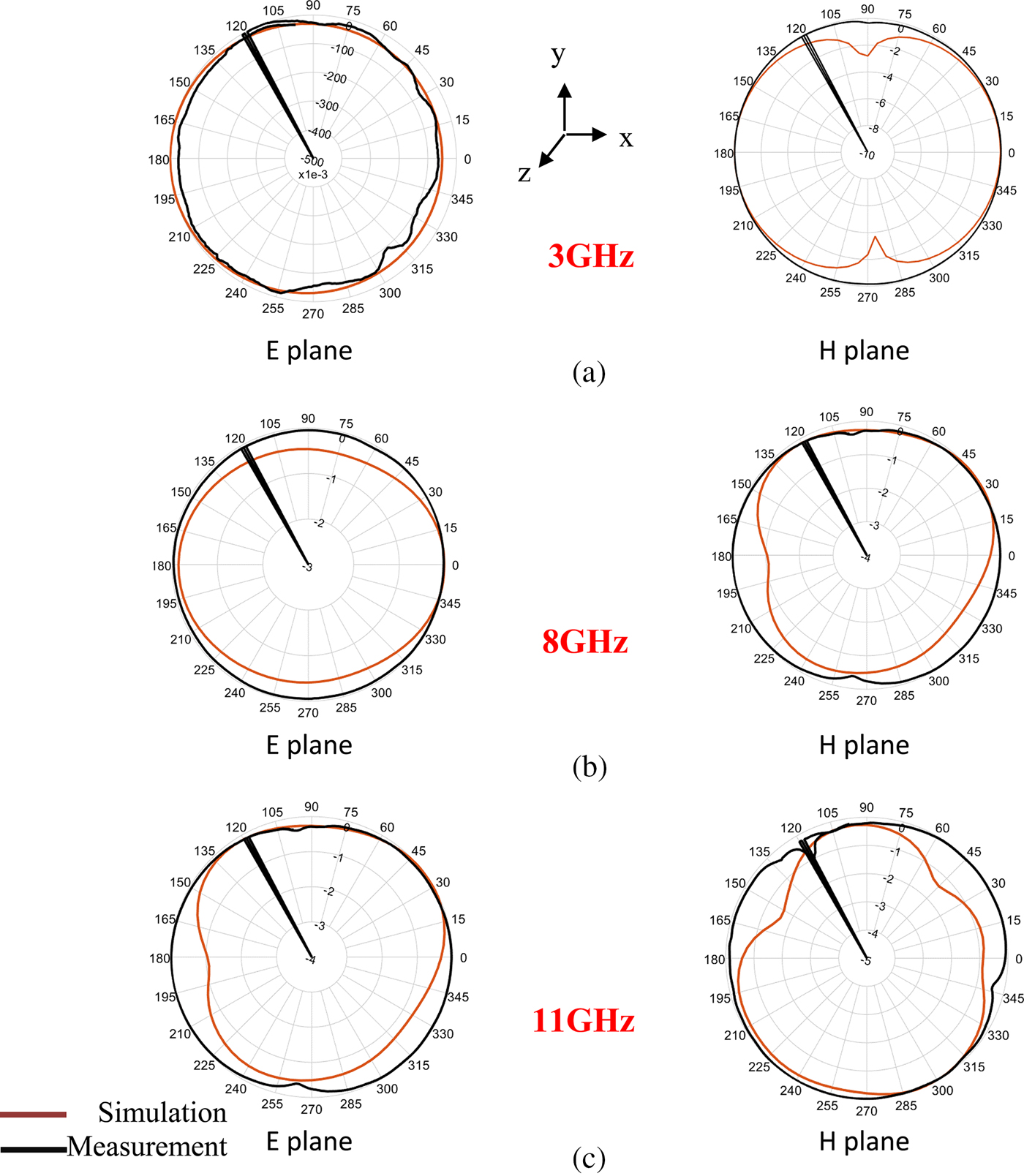
Figure 12 shows the top and bottom views of the fabricated antenna. Figure 13 shows the comparisons of the measured data and simulated results of VSWR and reflection coefficient S_11. Figure 14 shows the comparison of the measured data and simulated results of radiation pattern at frequencies 3, 8, and 11 GHz, and also shows that very good agreement is achieved and that the two band rejections are obtained precisely.

Fig. 12. The photos of fabricated antenna: (a) top side and (b) bottom side.

Fig. 13. Comparison of simulated results and measured data: (a) VSWR and (b) reflection coefficient S_11 (dB).

Fig. 14. Comparison of simulated results and measured data of antenna radiation patterns: (a) 3, (b) 8, and (c) 11 GHz.
Conclusion
In this paper, a SWB microstrip fractal antenna is proposed, designed, simulated, fabricated, and measured. The proposed antenna bandwidth is about 160%, which is designed for the frequency range of 2.6–40 GHz. The use of fractal configuration with an oval ground plane made possible this very broad bandwidth as well as an achieved significant compactness. By using a rectangular SRR and enhanced U-slot in the microstrip feed-line, we could accurately make two rejection bands for WiMAX and WLAN. The measurement data from the fabricated prototype antenna show good agreement with the results of fullwave HFSS software.
Author ORCIDs
N. Azadi-Tinat, 0000-0001-6334-5610.
 S. S. Abdpour received his B.Sc. degree from Islamic Azad University, Dehdasht, Iran in 2007 and his M.Sc. from the Shahrood University of Technology, Shahrood, Iran in 2018. His research interests include antennas and passive microwave devices.
 N. Azadi-Tinat received his B.Sc. degree from the Amirkabir University of Technology, Tehran, Iran, in 2003, and his M.Sc. and Ph.D. degrees in electrical engineering from the Iran University of Science and Technology, in 2008 and 2014, respectively. In 2014, he joined the department of electrical and robotic engineering, Shahrood University of Technology, Shahrood, Iran, where he is now an assistant professor. His research interests include antennas, active and passive microwave devices, and propagation theory.
 H. Oraizi (SM'98) received his B.E.E. degree from the American University of Beirut, Beirut, Lebanon, in 1967, and his M.Sc. and Ph.D. degrees in electrical engineering from Syracuse University, Syracuse, NY, in 1969 and 1973, respectively. From 1973 to 1974, he was a Teacher with the K. N. Tousi University of Technology, Tehran, Iran. From 1974 to 1985, he was with the Communications Division, Iran Electronics Industries, Shiraz, Iran, where he was engaged in various aspects of technology transfer mainly in the field of HF/VHF/UHF communication systems. In 1985, he joined the Department of Electrical Engineering, Iran University of Science and Technology, Tehran, Iran, where he is currently a Full Professor of electrical engineering. He teaches various courses in electromagnetic engineering and supervises theses and dissertations. Dr. Oraizi is a Fellow of the Electromagnetic Academy the Japan Society for the Promotion of Science.
 J. Ghalibafan received his B.Sc. degree from the Ferdowsi University of Mashhad in 2007 and his M.Sc. and Ph.D. degrees from the Iran University of Science and Technology in 2009 and 2013, respectively. In 2014 he joined the Department of Electrical Engineering, Shahrood University of Technology, Shahrood, Iran, where he is now an Assistant Professor, and the head of Antenna & Microwave Lab. His research interests include the analysis, design, and measurement of artificial electromagnetic materials; antenna and microwave devices; metamaterials; and magnetic materials.