


Introduction
The continued growth of data traffic and device connectivity has caused significant and profound effects on everyday life and social activities of people. In view of the extraordinarily fast growth in wireless consumer products and prevailing growth in the Internet of Things, the numbers of mobile networking devices are expected to surpass 100 billion by the year 2020 [Reference Ming1]. Mobile information traffic is also doubling (at least) every year and by 2019, the demand for multimedia or other data-hungry smartphone applications will surpass that for wired traffic [Reference Afif, Federico, Volker, Katsutoshi, Patrick and Michal2]. In the future, while a majority of individuals are receiving 10 megabits (Mb/s) of streaming backed through 4G-mobile, major research institutions and WiFi providers are beginning to develop the next generation system, namely the fifth-generation (5G) of wireless networks. 5G will be capable of handling data rates higher than 1 Gbps or preferably around 10 Gbps. Other significant advantages include power efficiency, low latency, and a much higher number of smart devices connected. Future 5G structure of cell frameworks will utilize millimeter wave (mm-wave) frequencies. 5G will be relied upon to offer to a wide range and multi-Gigabit-per-second (Gbps) information rates for versatile interchanges. Its application is mixed media, live 3D video, high-end cloud data, and intelligent gaming [Reference Jeffrey, Stefano, Wan, Stephen, Hanly, Anthony and Jianzhong3].
Antenna design for modern cell phones is by all accounts a challenging task. Future 5G global standards and promotion of 5G networks require much smaller yet proficient antennas. Antenna design depends upon the operating frequency and required bandwidth. In order to align the uniformity of mm-wave frequencies globally, the international telecommunications union (ITU) published a list of proposed frequencies of 24–86 GHz (24.25–27.5, 31.8–33.4, 37–40.5, and 40.5–42.5 GHz) [4].
The atmospheric attenuation affects RF signals as we increase signal frequency. The attenuation in the free space is largely caused due to signal absorption by atmospheric gasses such as O2 and H2O. This absorbing effect increases exponentially from 45 to 60 GHz as shown in Fig. 1 [5].

Fig. 1. Average atmospheric absorption of mm-wave.
Average atmospheric absorption of mm-wave at the sea level shows lowest attenuation with the highest frequency in the region of 5G spectrum from 26 to 43 GHz. Moreover, the federal communications commission (FCC) issued a notice of proposed rules for flexible services over 28, 37, 39, and 64–71 GHz bands [6]. 5G services will thus be needing a spectrum in the range of 26, 28, and 43 GHz.
5G wireless antennas have more challenges with the use of mm-wave frequencies, since the design flexibility, quality, and reliability with high bandwidth and reduced multipath fading are the primary factors [Reference Yong, Chunting, Hongwei, Ning, Hualong and Xiali7, Reference Wu, Cheung, Yuk and Sun8]. Defected ground structure (DGS) elements have been widely used to improve the working efficiency of filters, coplanar waveguides, microwave amplifiers, and antennas. The advantages of using DGS elements are: smaller component size, improved bandwidth, harmonic suppression, and unwanted cross-polarization of higher orders [Reference Amit and Mithilesh9]. DGS leads to disturbances that disrupt the uniformity of the ground and continuity of the surface currents. DGS symmetrical structures function as resonant gaps that are directly added on either side of a microstrip line so that the feed line can be connected efficiently. DGS also alters the shield current distribution of a defect in the ground to facilitate controlled excitation and the propagation of electromagnetic energy through the substrate, thereby changing the transmission line's capacitive and inductive response. This means DGS increases the effective capacitance of an antenna or filter to produce a multiband antenna [Reference Mukesh, Binod and Sachin10], which results in the development of multiple resonant frequencies [Reference Gary11, Reference Ashwani and Ashwani12]. The desired resonant frequency can be tuned by selecting appropriate geometry and positioning at the correct places for the designed antenna. Several wideband and multiband antenna configurations have already been reported, with DGS being incorporated in the radiating patch or ground level as symmetry/asymmetry and with a single/period structure as slots or apertures [Reference Korany and Ahmed13–Reference Amanpreet and Rajesh15]. The short wavelength at mm-wave frequencies, a compact antenna design enables easy integration into smartphones, wireless LAN bridges and tablets by using a wide variety of tiny antenna components. Meta-material structures have been utilized in several studies for the applications of energy harvesting and absorption. For instance, a wideband meta-material absorber was proposed in [Reference Bagmancı, Karaaslan, Una and Özaktürk16, Reference Akgöl, Özaktürk and Karaaslan17] that was independent of polarization and angle of incidence. Solar energy absorbers can also be designed using a plus-shaped meta-material structure [Reference Unal and Bagmanci18]. Material characteristics can also be characterized using triangular split ring resonator-based meta-material structure [Reference Bakır, Muharrem, Dincer and Sabah19]. Similarly, mushroom–shaped electromagnetic bandgap structures have been employed for pattern reconfigurable low profile antennas in [Reference Alkurt and Karaaslan20].
Several published reports suggest using mm-wave antennas in one or more 5G bands. It has been demonstrated that the gain and efficiency of the air-filled slot antenna is significantly improved as compared to conventional slot antennas, as most of the current flow at the edges of the slot [Reference Naser, Ming and Gert21]. Air-filled slot antenna efficiency is improved over conventional slot antenna by 0.5 dB from 27 to 28 GHz. It has more than 13 dB gain for 0–50° of the scan. A new design has been proposed for 5G mm-wave application, where a leaf-shaped bow-tie antenna has been used with eight elements of the linear-phased array [Reference Naser, Ming and Gert22]. Two sets of arrays are used at different places to have a large range of beam-steering area and good coverage. A 10 dB gain is achieved at different scanning angles using this design. Wide bandwidth is achieved from 25 to 40 GHz with 45% fractional bandwidth [Reference Nadeem, Osama, Muhammad and Saleh23]. A slotted substrate-integrated waveguide antenna is a good option for directional and dual-band antennas with high gain. The antenna is tuned at 28 and 38 GHz with −25 dB return loss. The 28 GHz band has a spectral bandwidth of 0.5 GHz with 5.2 dB gain and the 38 GHz band has 2.2 GHz spectral bandwidth with 5.9 dB gain. A mono-layered circularly polarized L-shaped patch antenna is proposed in [Reference Hanieh, Abdolali, Rashid, Alessandra and Pedram24].
Antenna design procedure and modeling
Design of 1 × 4 phased array elliptical inverted T-shaped slotted sectored patch antenna starts with a single element, 1 × 4 phased array and beam steering are subsequently added. A single element is designed by stubs and slots to have multi-band and wide bandwidth. The antenna bandwidth is enhanced by an elliptical-shaped aperture outside the radiating patch, stubs, and DGS. High gain and beam-steering capabilities of the antenna are achieved by the phased array. Dimensions of the antenna array are designed in such a way that the design can be integrated into any compact modern smartphone.
Configurations of inverted T-shaped slotted/sectored patch antenna
The proposed antenna is designed on top of Rogers RO4533 (lossy) substrate with dimensions of 10 × 10 mm2, dielectric constant (εr) of 3.3, loss tangent (tan δ) of 0.0025, and thickness (h) of 0.762 mm. Initially, a sectored radiated patch is designed with a radius (R) of 1.5 mm having a sector of the disk on one side and another side is like a cone. The antenna patch is fed by a coplanar waveguide where the width of the central microstrip line is 1 mm and, l 3 = 3.55 mm as shown in Fig. 2(a).

Fig. 2. The geometry of inverted T-shaped slotted sectored radiating patch antenna: (a) top plane and (b) defected ground plane.
A π-shaped slot is etched across the feed line to create a notched band of 32.5–39.5 GHz. Inverted T-shaped stub across the sectored patch is introduced along with the slots on the parasitic element (as shown in Fig. 2(a)) to resonate antenna at multi-bands with ultra-wide bandwidth. A DGS is generally a slot of a certain shape in the ground layer of the antenna. The slot in the ground plane disturbs the current distribution and alters the resonance frequency depending on the inductive effect of the DGS structure. This changes the propagation of EM waves through antenna substrate layers; therefore, a specific resonance can be obtained by tuning different structures. This can also lead to an improved bandwidth if the resonance is close to the operating band of the antenna otherwise multiband antenna can be obtained [Reference Arya, Kartikeyan and Patnaik25]. A number of iterations of bracket-shaped DGS are introduced in the ground plane of the antenna to increase the bandwidth as shown in Fig. 3. The next step is to incorporate the antenna design into a phased array configuration. Therefore, a 1 × 4 phased array is configured in a linear plane with dimensions of 10 × 44 mm2 as shown in Fig. 4. Computer simulations with the CST Microwave Studio were used to analyze the antenna characteristics. Antenna parameters are shown in Table 1.

Fig. 3. Return loss (S 11) of the designed antenna with and without DGS.

Fig. 4. An elliptical slot with T-shaped slotted sectored radiating patch 1 × 4 array with DGS.
Table 1. The dimensions of the designed antenna

Bandwidth enhancement using slots and stubs
The technique used to increase the bandwidth, in this case, is the use of slots on the parasitic element that are indirectly coupled with antenna patch and stubs on sectored patch antenna. Figure 5(a) shows the geometry of the antenna with the parasitic elliptical element. Initially, a stub on top of the sectored patch with a notch on the elliptical element is introduced to improve the return loss. In the second iteration, a stub on the right and left sides of the sectored patch are added with a dimension of 2.6 × 0.1 and 2.58 × 0.1 mm2, respectively. On the elliptical parasitic element at the end of the T-shaped metallic patch, slots of dimensions 0.42 × 0.1 mm2 at right and left sides of the elliptical parasitic element are etched as shown in Fig. 5(c). By introducing an inverted T-shaped metallic patch around sectored radiator bandwidth of each band increased significantly, as shown in Fig. 6. In the third iteration, to make the antenna resonate at 28 GHz and to create multi-band around the 64 GHz, the length of the upper stub l 1 is increased to 1.58 mm and two slots of length l 5 = 2.47 mm and width w 5 = 0.1 mm is etched at the right and the left sides of the T-shaped sectored patch as shown in Fig. 5(d).

Fig. 5. The evolution of sectored patch antenna: (a) sectored patch, (b) sectored patch with notch, (c) sectored patch with inverted T-shaped stub and (d) sectored patch inverted T-shaped slotted.

Fig. 6. The transition of bandwidth improvement.
Antenna bandwidth is significantly improved by introducing stubs and slots as shown in Fig. 7. Antenna-1 consists of a sectored patch and antenna-4 is sectored patch with an inverted T-shaped slotted sectored. A comparison of antenna bandwidth is shown in Fig. 6. Antenna-4 is wideband at 43 and 51 GHz, but around 28 and 72 GHz there are multi-bands.

Fig. 7. Return loss (S 11). Comparison between the simple sectored patch and inverted T-shaped slotted sectored patch.
Effect of DGS
The double bracket-shaped slots are etched in the ground as DGS to alter the existing current distribution. The CST Studio Suite is used for antenna design, simulation, optimization, and analytical evaluations. Figure 1(b) shows the design parameters of the antenna suggested in the software. The antenna's middle ground plane consists of four bracket slots each with a width of 0.1 mm. It began with the incorporation of a ring slot around the center with a radius of 2 mm. The idea is to disturb the current distribution on the stubs of a radiating patch which is indirectly coupled with the DGS ring slot. There are several design parameters, including slot width, ring diameter, split ring fraction, and slot placing, which control the antenna impedance properties. At this stage of modeling, the parametric analysis of the design parameters was performed to obtain the antenna dimensions optimized and two bracket-ring slots were truncated in the opposite directions from the center of the ground at the same distance. This was to preserve symmetry.
DGS has a major effect on 53.5 and 69 GHz. Surface current distribution at these frequencies is shown in Figs 8 and 9, respectively. The high current density at the edges of the ground slots as shown in Fig. 8 defines the high coupled effect of slots with the inverted T-shaped stubs that, ultimately combined by the partial ground in the broadband, is responsible for the introduction of resonances at 53.3 GHz as shown in Fig. 3. The same is the case for 69 GHz as shown in Fig. 9 but at this time coupling is not strong enough to have wideband. Multiple resonances are combined to obtain the ultra-wideband from 48 to 54.5 GHz and multi-bands around the 69 GHz region as shown in Fig. 3.

Fig. 8. Current density of proposed antenna at 53.5 GHz: (a) top view and (b) bottom view.

Fig. 9. Current density of proposed antenna at 69 GHz: (a) top view and (b) bottom view.
Phased antenna array
The antenna array configuration and the spacing between elements also affect the radiation pattern and impedance of the antenna. A single substrate is used for all the antennas. As the antenna is designed for four different frequencies so it is challenging to select the perfect distance between antenna elements to avoid grating lobes and have ±30° beam steering. The phased antenna array for three configurations (0.9λ at 26, 28, and 43 GHz) is modeled and simulated. Simulations show that at 26 GHz, d = 0.9λ ≃ 11 mm spacing between antenna array elements is good for beam steering. The equivalent circuit for the antenna array is a parallel-tuned circuit in series with the transmission line to which it is connected as shown in Fig. 10. The input and output impedances are those of the line segment and the related values L, C, and R depend on the dimensions of the antenna design and its location on the transmission line.

Fig. 10. Equivalent circuit of 1 × 4 antenna array.
Improvement in return loss especially for 28 and 69 GHz bands is observed as shown in Fig. 11. As the designed antenna has an elliptical parasitic element which is indirectly coupled with the radiating patch of the all antenna array elements, that is why impedance bandwidth is significantly increased as compared to a single element. The simulated result shows that the antenna array with DGS has four ultra-wide bands of 25.8–29.7, 40.6–44.6, 49.2–53.1, and 62.3–74 GHz with a maximum gain of 16.5 dBi at 51 GHz as shown in Fig. 11(a) and antenna array without DGS has three ultra-wide bands of 25.8–29.7, 40.6–44.6, and 62.3–74 GHz as shown in Fig. 11(b).

Fig. 11. Return loss (S 11) of the elliptical slot with T-shaped slotted sectored radiating patch 1 × 4 array: (a) with DGS and (b) without DGS.
Beam steerable antennas for mobile phone applications
The antenna set is used as shown in Fig. 12 at the top and bottom of the mobile phone PCB. We have placed an array antenna in such a way that a signal from at least half of the space above and below can be received as shown in Fig. 12. For this, two 1 × 4 antenna arrays are proposed at the top and bottom of mobile phone PCB with beam-steering capabilities. The proposed antenna has a highly effective beam-steering capability of ±30° at 26, 28, and 43 GHz. The values of the antenna array parameters are listed in Table 2.

Fig. 12. Side view of the proposed 5G antenna: (a) front side, (b) back side, and (c) antenna Array.
Table 2. The dimensions of the antenna array

Here, d = 0.9λ ≃ 11 mm represents the distance between the center of the antenna element array where λ = 11.53 mm (26 GHz). The L s = 10 mm represents the length of the antenna array. The Ws = w 1 × d = 10 × 11 = 44 mm is the width of the antenna array. Dimensions of iPhone XS Max antenna were taken as a reference for the proposed antenna.
Figure 13 shows a system architecture where 5G applications employ the proposed antenna package. These are four element radiating arrays with each one having a phase shifter of its own. All elements are linearly arranged in a matrix array in the complete phased array antenna. The feed network can be operated with low loss phase shifters to steer the beam. A microwave switch can easily be selected among these sub-arrays as shown in Fig. 13.

Fig. 13. Phase shifting network for the array antenna.
Results and discussion
In the following sections, simulation outcomes of an elliptical inverted T-shaped slotted sectored patch antenna with DGS output are summarized. The proposed antenna shows significantly improved features including, large bandwidth, high efficiency, and acceptable insulation between antenna elements.
Bandwidth
The return loss of the proposed antenna array, with and without DGS is shown in Fig. 14. The simulated results show that without DGS, the antenna resonates at 28, 43, and 64 GHz bands whereas with DGS the same antenna resonates at 28, 43, 51, and 64 GHz with different bandwidths as listed in Table 3.

Fig. 14. Return loss(S 11) of elliptical sectored T-shaped sectored with and without DGS.
Table 3. BW comparison b/w T-shaped sectored with and without DGS
The ultra-wide tetra band is in the region where average atmospheric absorption of mm-wave is optimal at 24–32 GHz (0.15 dB/km), 35–47 GHz (0.15–0.2 dB/km), and 64–74 GHz (3–0.4 dB/km) [Reference Shao, Ming and Yan26]. Table 3 shows a bandwidth comparison between T-shaped sectored patch antenna, with and without DGS. Antenna with DGS has more bandwidth than the antenna without DGS.
Gain
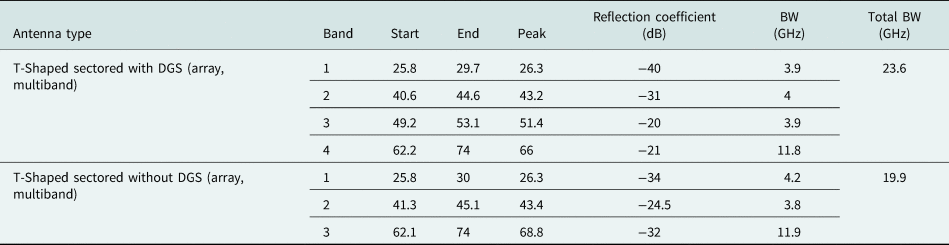
A single element has gain in the range of 6–9 dBi with an omnidirectional radiation pattern but the antenna arrays have gain within a range of 12–16.5 dBi with the sharp beam. Figure 15 shows the simulated antenna array results with maximum gain over the frequency range from 25 to 76 GHz. The antenna gain, with or without DGS, over the entire range is not less than 12 dBi. The proposed antenna has a peak gain of 16.5 dBi at 51 GHz. Simulated results listed in Table 4 show a gain comparison between elliptical T-shaped sectored patch antenna with and without DGS for all ultra-wide tetra bands.
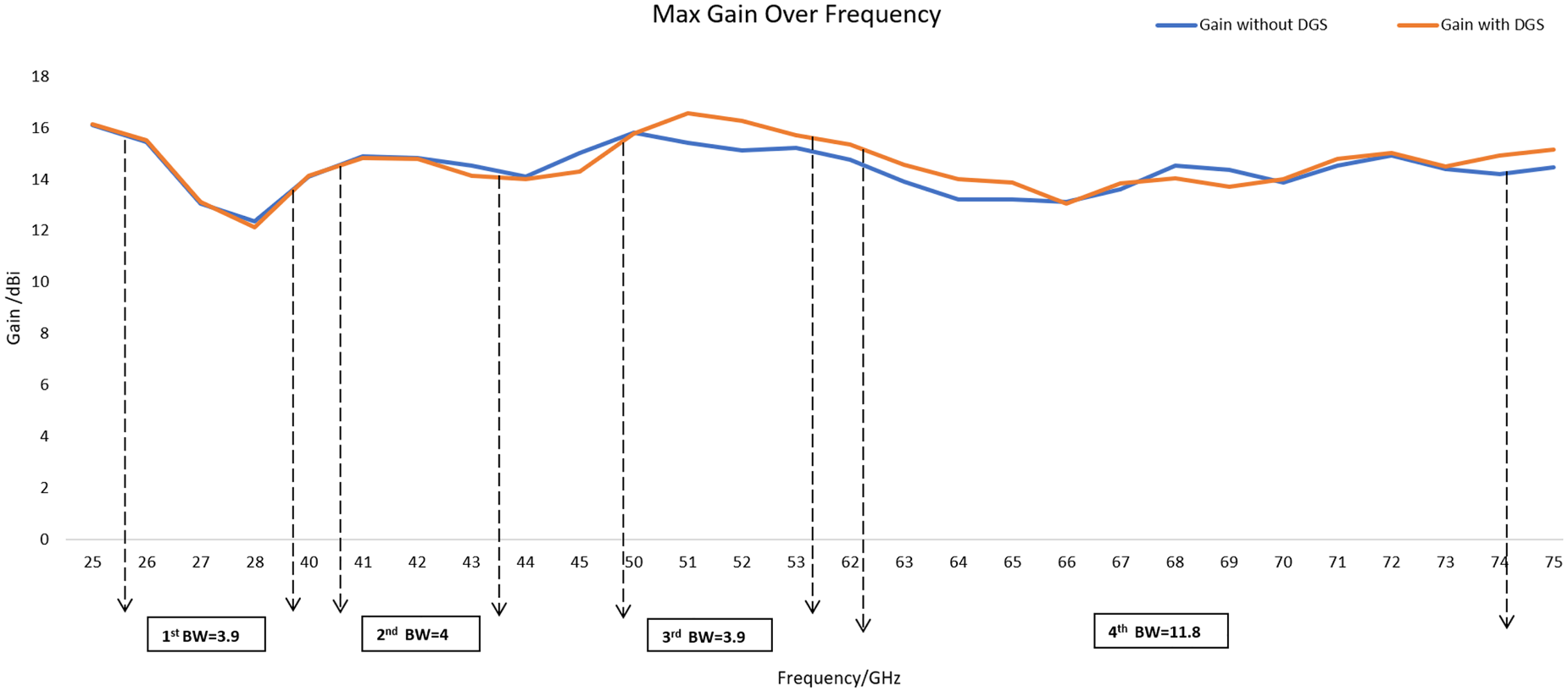
Fig. 15. Maximum gain over frequency and BW.
Table 4. Gain comparison b/w elliptical T-shaped sectored with and without DGS

Radiation pattern and beam steering
The system consists of a beam-forming antenna or a number of antennas as a set. The signal to be transmitted is fed each antenna component separately. All antenna feed, however, is controlled so that every component can be controlled in phase and amplitude. It generates an interference pattern that is positive and disruptive in the wavefront. A beam antenna array can be generated with several antenna components that are very spaced apart. The required phase movement can be calculated with the sine theorem:
 $$\Delta \varphi = \;\displaystyle{{2\pi \cdot d\cdot \sin \Theta s} \over \lambda }$$
where Δφ is the phase shift between two successive elements, d is the distance between the radiating elements, and Θs is the beam steering. The phase shift is a phase difference between two successive elements of an array which is constant and called phase increment. The change in phase shift with beam-steering values is shown in Table 5.
Table 5. Change in phase shift for different beam-steering values

The 3D radiation patterns of array antenna package operating at 26, 28, and 43 GHz at a scanning angle of 0° are shown in Fig. 16. The antenna shows a good radiating pattern at 26 and 28 GHz but at 43 GHz it has high side lobes which is due to the physical limitation of the antenna.

Fig. 16. 3-D radiation pattern of the antenna array at: (a) 26 GHz, (b) 28 GHz, and (c) 43 GHz.
The radiation pattern for 26, 28, and 43 GHz can be steered in the theta plane from −30 to 30° using an appropriate phase shifter to each element as shown in Fig. 13.
As with any directional antenna, a number of side lobes are formed. In cases where the spacing is less than the wavelength, the side lobes appear on either side of the main lobe with decreasing levels [Reference Saeed and Qunsheng27]. At 26 GHz the wavelength is λ = 11.58 which is less than the spacing between the antenna array element d = 11 that is why there are very minor side lobes at 26 GHz as shown in Fig. 13. At 28 and 43 GHz the wavelengths are smaller than 26 GHz so spacing is wider than the wavelengths, that is why side lobes more prominent as shown in Figs 17 and 18.

Fig. 17. E-plane radiation pattern of the antenna array at 28 GHz on: (a) θ = 0°, (b) θ = 15°, and (c) θ = 30°.

Fig. 18. E-plane radiation pattern of antenna array at 43 GHz on: (a) θ = 0°, (b) θ = 15°, and (c) θ = 30°.
The proposed antenna includes a parasitic element for bandwidth improvement but it has disadvantage of large antenna size as compared to λ/2 antenna, which creates a problem of grading lobes with beam steering for 26, 28, and 43 GHz. If you steer too far with a phased array, a grating lobe happens and the main beam reappears on the wrong side. For a 30° look angle, maximum distance between two arrays (d max) must be (2/3) × λ [Reference Saeed and Qunsheng27] which is an actual trade-off between ultra-wide tetra band and beam steering. It is clear from Figs 19(c), 17 and 18, that a slight variation in directivity can change the beam steering of antenna and limits this to maximum 30°.

Fig. 19. E-plane radiation pattern of antenna array at 26 GHz on: (a) θ = 0°, (b) θ = 15°, and (c) θ = 30°.
Characteristic comparison between different antennas already designed and the proposed antenna is shown in Table 6. It is evident that the proposed antenna has ultra-wide tetra band with improved gain as compared to the referenced antennas. It has more than 12 dBi gain in all four bands. The dimensions of the proposed antenna are comparable or large except for the last antenna [Reference Mohsen, Rahim, Pei and Ahmed32]. As far as the size of the proposed antenna is concerned, it has an optimal size to fit into any mobile phone as shown in Fig. 12. Due to multiple bands and bandwidth improvements, there are some limits on the dimension of the antenna as explained earlier where the proposed antenna cannot steer beam >±30°.
Table 6. Comparison with the state-of-the-art mm-wave antenna designs

Conclusion
A novel 1 × 4 phased array elliptical T-shaped slotted sectored patch antenna with DGS for 5G application with ultra-wide tetra band is proposed. The antenna can be efficiently employed at four different bands: 25.8–29.7, 40.6–44.6, 49.2–53.2, and 62.2–74 GHz with a maximum gain of 16.5 dBi at 51 GHz. The gain is not less than 12 dBi in any band, which is quite high. The antenna can be fitted into any modern compact mobile phone with very little mutual coupling. To have a wide coverage area, the antenna package can be fabricated on the top and bottom edge of PCB in any mobile phone with a steering angle of ±30° at 26, 28, and 43 GHz with a maximum gain of 16.5 dBi in the xy-plane. It is quite evident from these results that the proposed mm-wave antenna is an excellent candidate for 5G applications, particularly in cellular infrastructures. Availability of 11.8 GHz bandwidth in the contiguous non-licensed spectrum in the 62.2–74 GHz band will pave the way forward to launch new exciting technologies utilizing fiber-like wireless connectivity.
Acknowledgement
The authors would like to acknowledge Dr. K.M. Hassan, Chairman EE at the University of Engineering and Technology Lahore and Mr. C.L. Ahmad (father of M. Anas) for their continuous support and motivation during the research.
 Muhammad Anas was born in Chiniot, Punjab, Pakistan, in 1992. He received his BSc degree in Electrical Engineering (Telecommunication) from Government College University Faisalabad, Punjab, Pakistan. He is currently pursuing his MSc in Electrical Engineering (Electronics and Communication) from the University of Engineering and Technology Lahore, Pakistan.
 Hifsa Shahid is Assistant Professor at the University of Engineering and Technology Lahore (KSK campus), Pakistan and is presently working as a Postdoctoral fellow at the School of Science and Engineering, Reykjavik University, Iceland. She has completed Ph.D. in Electrical Engineering from the University of Sheffield, UK in 2012. Her fields of expertise are semiconductor devices, solar PV, and optics.
 Abdul Rauf is working as Associate Professor at the National University of Sciences and Technology (NUST), Pakistan. He has done MSc in Telecommunication Engineering from DTU, Denmark in 2004 and Ph.D. from the University of Sheffield, UK in 2011. He has research interests in the fields of telecommunication engineering and optical sensing in smart materials.
 Abdullah Shahid is pursuing BSc in Electrical Engineering at the University of Engineering and Technology Lahore, Pakistan.


