


Introduction
In recent years, on-body health monitoring devices have attained great popularity. The ongoing miniaturization of sensors has enabled the future healthcare module to integrate into wearable devices. Wide range of applications has been incorporated with wearable devices in the field of proactive health monitoring, training of military/sports person, personal security, and personal computing. Physiological parameters, such as glucose level, blood pressure, temperature, are continuously measured from the human body. Measured information is synchronized with a PC or mobile phones for monitoring and storing [Reference Chen, Gonzalez, Vasilakos, Cao and Leung1]. Therefore, the antenna is one of the most important parts of the healthcare modules for ensuring satisfactory power transfer from on-body wearable device to off-body monitoring device.
Several design challenges arise while designing the on-body antenna. Near-field electromagnetic radiations interact with multi-layered tissue structure (consisting of skin, fat, muscle, and bone) and produce internal reflection and scattering. It interrupts with impedance matching and degrades antenna performance [Reference Kiourti and Nikita2]. To overcome this issue, various design techniques have been used including cavity-backed surface-integrated waveguide [Reference Moro, Agneessens, Rogier and Bozzi3, Reference Agneessens4], meandered dipole with a reflector ground [Reference Al-Sehemi, Al-Ghamdi, Dishovsky, Atanasov and Atanasova5], electromagnetic band gap structure [Reference Gao, Hu, Wang and Yang6], antenna with artificial magnetic conductor [Reference Alemaryeen and Noghanian7], and multi-stacked patch [Reference Lilja, Salonen, Kaija and Maagt8]. These techniques provide good isolation between the antenna and the human body but have larger and complex geometry which make them difficult to integrate with wearable devices. Higher mode circular patch antennas with shorting pins [Reference Tak, Lee and Choi9], reconfigurable circular patch [Reference Tong, Liu, Liu, Guo and Yang10], and PIFA structure [Reference Lin, Saito, Takahashi and Ito11] have smaller dimensions; can be considered as a good candidate for wearable devices; however, they have an undesired larger height. Wide bandwidth is also the one major necessity to ensure stable performance when the antenna is placed on different human being [Reference Shakib, Moghavvem and Mahadi12]. A significant shift in the resonating band has been observed due to structural deformation in [Reference Hu, Gao, He, Cong and Zhao13]. Maximum SAR limit also restricts the radiated power of the antenna. Besides this, multipath fading occurs due to different body postures and movements. Therefore, to enhance the quality of the signal transmission of wearable devices, multiple input multiple output (MIMO) antennas are attaining much attention by researchers. Very few literatures are available for wearable MIMO antenna structures. Dual-band textile MIMO antenna [Reference Yan, Soh and Vandenbosch14], ultra-wide band (UWB) MIMO antenna with a decoupling structure [Reference Biswas and Chakraborty15], and neutralization line-based UWB MIMO antenna [Reference Biswas and Chakraborty16] for wearable device have been investigated but [Reference Yan, Soh and Vandenbosch14–Reference Biswas and Chakraborty16] are designed using textile materials, possess large footprints, and their performance is also affected due to wrinkling, crumpling, and environmental effects. Ground radiation-based loop antenna with two inductive radiators [Reference Qu, Piao, Qu, Kim and Kim17], circular co-radiator antenna with high impedance surface [Reference Dingliang, Yang, Max and Hanyang18], and four-element octagonal ring-shaped MIMO [Reference Chouhan, Panda, Khushwah and Mishra19] are designed for wearable MIMO devices. Authors have used a rigid FR-4 substrate which is not comfortable for the user to wear, and SAR is also not evaluated in [Reference Qu, Piao, Qu, Kim and Kim17]. Large separation gap between antenna elements is used by researchers to enhance the port isolation which unnecessarily increases the overall size of the MIMO structure.
In this paper, a compact, open-end slotted MIMO antenna structure has been proposed for wearable devices operating at 2.45 GHz (industrial scientific and medical (ISM)) band. First antenna size is miniaturized so that it can be easily integrated with compact on-body devices. After that, a wide bandwidth of 300 MHz is achieved with the help of modified L-shaped ground that makes the antenna robust to withstand frequency detuning. Finally, two antenna elements are used to design the MIMO structure for enhancing the signal transmission quality. Inverted U-shaped stub is deployed at the ground plane to improve port isolation. Depending on the application of proposed antenna, stringent approaches such as miniaturization, wide operating bandwidth, high port isolation, high directivity, and low specific absorption rate are accomplished by the proposed antenna structure.
Antenna design procedure
The antenna is designed on a thin semi-flexible substrate of Rogers 5880 (εr = 2.2, loss tan = 0.0009) with a thickness of 0.51 mm. The dimensions of single-element antenna structure are only 14 mm × 25 mm that is equal to 0.114λ o × 0.204λ o, where λ o is the free space wavelength at the resonating frequency of 2.45 GHz. Miniaturization is attained through etching four open-end slots on the rectangular patch along the x-axis on both the sides. L-shaped partial ground plane is used for better impedance matching and wider bandwidth. Length of the slots and other parameters are optimized to tune the desired resonance using Computer Simulation Technology (CST) microwave studio.
As the antenna is designed to be operated on the human body, all the simulations and optimization during design process performed on the three-layered tissue model consist of skin (εr = 38 and σ = 1.46 s/m), fat (εr= 5.2 and σ = 0.10 s/m), and muscle (εr = 52.7 and σ = 1.8 s/m). The planar dimension of tissue modal is 40 × 60 mm2 and its properties are taken according to [Reference Gemio, Parron and Soler20, Reference Chen, Gao and Du21]. The geometrical structure of single-element antenna along with on-body simulation setup and surface current distribution is shown in Fig. 1.
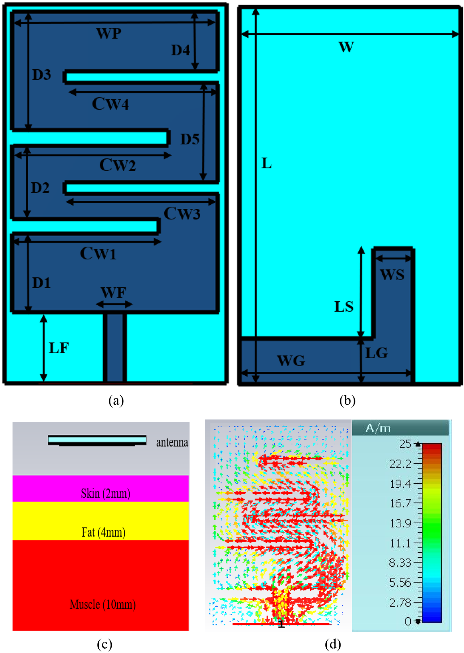
Fig. 1. Structure of single-element antenna with simulation setup and surface current distribution: (a) top view, (b) bottom view, (c) simulation setup, (d) surface current.
Stepwise evaluation of single radiator antenna
Stepwise design evaluation of antenna is represented in Fig. 2. Comparison of reflection coefficient S 11 for all the design steps is shown in Fig. 3. The proposed structure is initially designed as a rectangular microstrip patch with the partial ground plane. By etching multiple open-end slots, this structure is modified to resonance at a desired 2.45 GHz frequency.
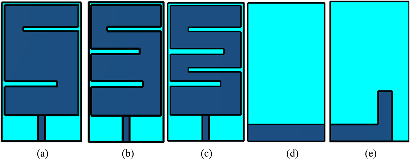
Fig. 2. Stepwise structure of single-element antenna: (a) step 1 front view, (b) step 2 front view, (c) step 3 and step 4 front view, (d) back view for step 1–step 3, and (e) step 4 back view.
Fig. 3. Reflection coefficient of single-element antenna design steps.
In step 1, the antenna is designed by cutting two open-end slots at the two opposite corners of the radiator. First slot is etched at the lower left corner which provides wideband resonance at 3.5 GHz. Length CW1 of the slot is varied from 8 to 11 mm to obtain optimal performance. From Fig. 4(a), it can be observed that increasing the length of the slot helps to reduce the resonating band but degrades impedance matching. Therefore, CW1 = 9 mm is considered for further design which provides resonance at 3.9 GHz. Second slot is etched at the upper right corner which adds inductive effect in the structure. It helps to reduce the resonating band from 3.9 to 3.0 GHz with good impedance matching. Effect of varying length CW4 is shown in Fig. 4(b). The increasing value of CW4 has an almost negligible effect on return loss.

Fig. 4. Effect of varying slot lengths on reflection coefficient in step 1: (a) varying CW1 and (b) varying CW4.
In step 2, a new slot parallel to the first slot is etched that induces the inductive effect and shift the antenna resonance at 2.8 GHz. Impedance plot for the evaluation steps of the antenna is shown in Fig. 5. In step 2, reactance shifts upward which shows high inductive reactance (xl = ωl) in impedance. The high value of inductance helps to lower the resonance from 3 to 2.8 GHz. The optimal value of this slot is taken as “CW2 = 7mm” for the design.

Fig. 5. Plot for input impedance: (a) real part and (b) imaginary part.
Further in step 3 (Fig. 2(c)), another slot is etched parallel to the top right slot to achieve the resonance at 2.45 GHz. Reactance plot shifts downward making impedance more capacitive (xc = 1/ωc). From Fig. 3, it can be found that a reflection coefficient of 20 dB and a bandwidth of 120 MHz are obtained in step 3. It is well known that the human body is a complex structure with multiple tissue layers. The thickness and electric properties of tissue layers vary for different body parts as well as for the individual. It was studied in the present literature that antenna frequency may detune and impedance matching degrades when subjected to various parts of the body [Reference Tak, Lee and Choi9, Reference Shakib, Moghavvem and Mahadi12, Reference Abbasi, Nikolaou, Antoniades, Stevanovic and Vryonides22, Reference Duan, Xu and Geyi23]. Thus, to overcome the limitation of frequency detuning and impedance mismatch in practical applications, the structure is modified by using defected ground structure in step 4.
Partial ground plane is converted into an L-shaped ground plane. It tends to reduce the quality factor (Q) and improve the bandwidth (BW) of the proposed structure (BW = Fr/Q). Impedance curve represents 50 ohm resistance and null reactance at 2.42 GHz. Reactance curve is shifting upward showing an increase in inductance value and reduction in Q-factor. Significant improvement in reflection coefficient from 13 to 40 dB and a bandwidth of 300 MHz is obtained without altering the central resonating frequency.
To analyze the working principle, a relationship among slot dimensions and the resonance frequency is established. Surface current distribution in Fig. 1(d) shows the resonating path at 2.45 GHz. Surface current has followed the meandered path through the open-end slots. Therefore, the length of the radiating path (LR) responsible for resonance can be calculated as

From Fig. 1 and data given in Table 1, LR = 47.3 mm. Here, the effective dielectric constant (Ereff) is calculated as 1.645. LR should be half wavelength at the resonance; therefore, resonating frequency f r1 at this length is
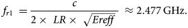
Table 1. Geometrical parameters of the proposed structure

It shows that the calculated frequency from the antenna design parameters is in good agreement with the desired frequency.
Design of MIMO structure
To design a MIMO antenna, two mirror image antenna elements are placed parallel to each other. It was difficult to maintain high isolation between two elements without a decoupling structure. Therefore, to improve the isolation, inverted U-shaped stub is added at the ground plane acting as a parasitic resonator. Length of this stub is 47 mm (2 × Lc + Wc), which is approximately equal to the value calculated in equation (1). Length of inverted U-shaped stub satisfies the resonating length at 2.45 GHz. The geometry of the MIMO structure is shown in Fig. 6. S-parameters of the antenna with and without ground stub are compared in Fig. 7. Adding of stub has enhanced the isolation from 11 to 32 dB.
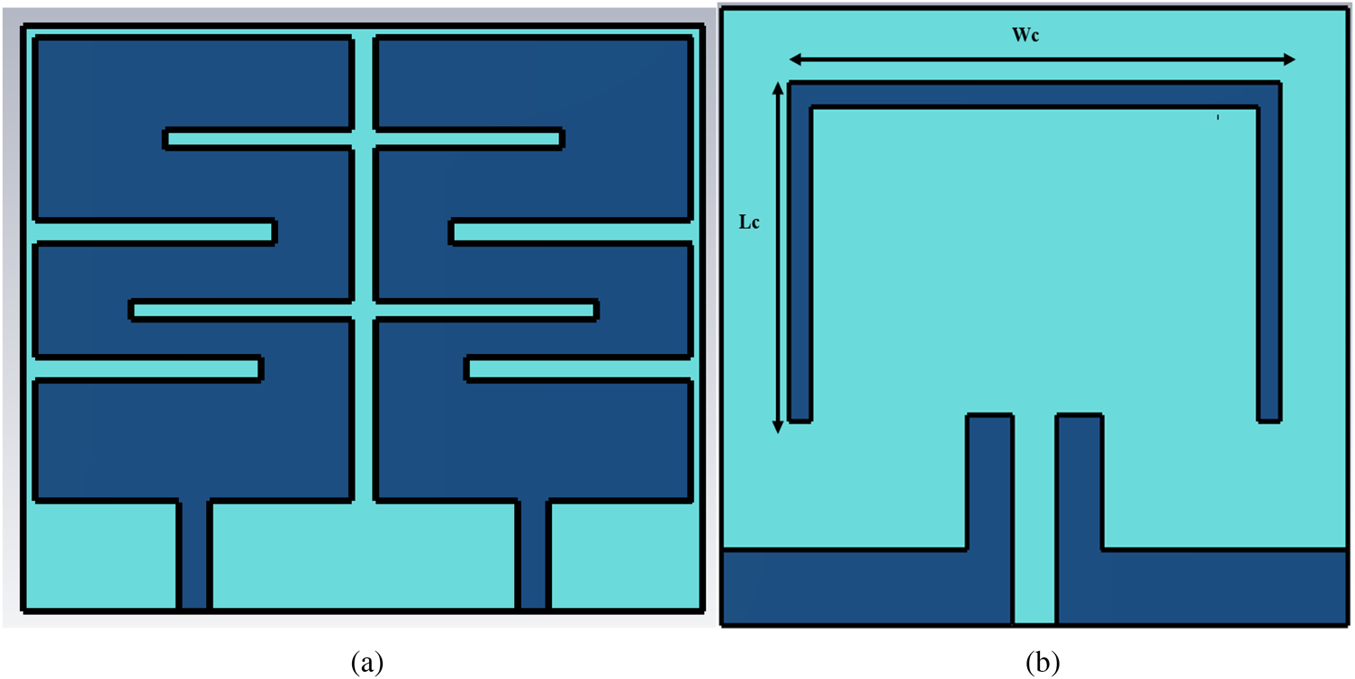
Fig. 6. Structure of MIMO antenna: (a) front view and (b) back view.
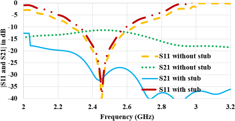
Fig. 7. S-parameters of MIMO antenna with and without stub.
The design approach for adding inverted U-shaped stub can be explained with the help of the surface current shown in Fig. 8. It can be observed that the current is excited from the open edge of the lowermost slot and the maximum current is followed through the slots. Therefore, decoupling stub is added from the current excitation point of radiator 1 to radiator 2. From the surface current plot (Figs 8(b) and 8(c)), it can be found that the current flowing from port 1 to port 2 is offset by the ground stub which reduces mutual coupling between antenna elements.

Fig. 8. Surface current distribution of MIMO antenna (a) without stub, (b) with stub front view, and (c) back view.
Effect of varying separation gap “s” between antenna and body tissue on antenna performance
The large variation in the permittivity of body tissue and antenna substrate causes varying effective dielectric constant of the antenna which significantly detunes the resonating band. Therefore, the antenna is placed at a gap “s” from the tissue model to avoid degradation of antenna performance. Human body keeps on moving, it is hard to maintain the constant separation gap all the time. For this reason, three different values of gap (s = 2, 4, 6 mm) are used to account the border of antenna reliability. Reflection coefficient, radiation efficiency, and gain plot for varying “s” are shown in Fig. 9.
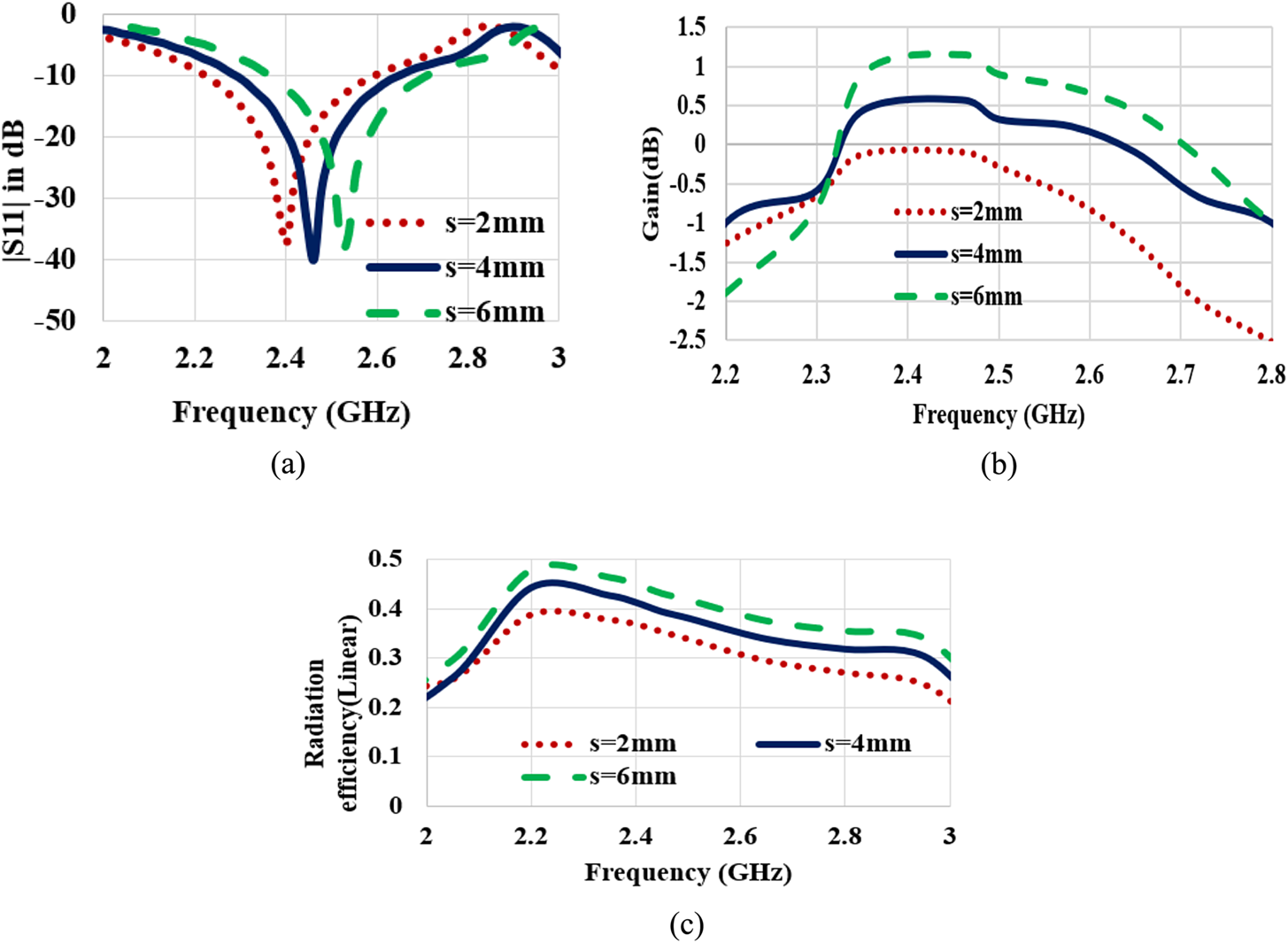
Fig. 9. Effect of varying “s” on antenna performance: (a) reflection coefficient, (b) gain, and (c) radiation efficiency.
Reducing the value of “s” causes lowering of central resonating frequency. From Fig. 8(a), it can be observed that due to wide bandwidth, the proposed structure can effectively cover the desired ISM band from 2.4 to 2.48 GHz for all values of s. At “s = 4 mm”, a resonating frequency of 2.45 GHz is obtained. Therefore, for all, the simulation and measurement value of “s” is kept at 4 mm.
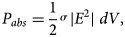
Antenna shows the lowest gain of −0.9 dB and an efficiency of 38% when placed in extreme proximity (s = 2 mm) of body tissue. Some of the near-field power is absorbed (P abs) by the tissue. It depends upon the conductivity (σ) of tissue layers and near-field electric field intensity (E) [Reference Kiourti and Nikita2]. Electrical field intensity in the near field is given in equation (4), which shows field intensity reduces with increasing distance from the antenna [Reference Prasad and Handa24]. Therefore, an improvement in the gain of 1.2 dB and in the efficiency of 8% is observed with increasing s from 2 to 6 mm.
Results and discussion
The proposed antenna is fabricated to validate the simulated results. Antenna parameters are measured using Agilent N5247A programmable network analyzer and anechoic chamber. The actual on-body performance of the fabricated antenna is measured on a pork loin. Photographs of the experimental setup are shown in Fig. 10.

Fig. 10. Photographs of the experimental setup: (a) antenna placed on pork loin, (b) return loss plot on VNA, and (c) antenna in an anechoic chamber.
S-parameters
Scattering parameters are measured to analyze the impedance matching and level of mutual coupling in terms of reflection coefficient (S 11) and transmission coefficients (S 21), respectively. Plot for simulated and measured S-parameters is shown in Fig. 11. Simulated 10 dB bandwidth is 300 MHz (2.3–2.6 GHz) whereas measured bandwidth is 480 MHz (2.12–2.6 GHz). Measured data reveal wider bandwidth as compared to the simulation data. A similar type of variation in simulated and measured results has been observed in [Reference Gao, Hu, Wang and Yang6, Reference Hu, Gao, He, Cong and Zhao13, Reference Koo, Hong, Park, Shin and Yook25]. Simulated and measured transmission coefficient shows that mutual coupling is less than −30 dB for the required ISM band.
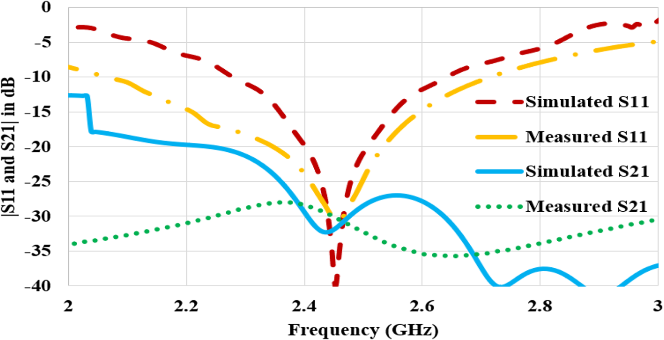
Fig. 11. Measured and simulated reflection coefficient.
Radiation characteristics
Simulated and measured E-plane and H-plane radiation patterns for excitation at port 1 are shown in Figs 12(a) and 12(b). It can be seen that broadside radiation pattern toward +z direction is offered by the antenna which is the required feature for the on-body antenna. Three-dimensional plot for directivity at 2.45 GHz is shown in Fig. 12(c). Maximum directivity of 4.56 dBi is obtained. Power is radiated away from the body. Each layer of body tissue has different permittivity and thickness which causes the internal reflection of electromagnetic waves. Therefore, superposition of antenna back radiation and reflections from the multi-layered human tissue introduces an improvement of directivity. The simulated and measured gain plot is shown in Fig. 12(d). It shows that antenna retains positive gain for the operating bandwidth.

Fig. 12. (a) E-plane radiation pattern, (b) H-plane radiation pattern, (c) simulated 3D radiation pattern at 2.45 GHz, and (d) plot for simulated and measured gain over the frequency.
Specific absorption rate
Near-field radiations of the wearable antenna affect the human body. Continuous exposure of radiations increases the temperature of the tissue. Heat is generated due to the non-radiating reactive near field. Excessive heat may damage cells and reduces the blood circulation causing a disturbance in the functioning of sensitive organs. Thus, it is necessary to consider the power absorbed by body tissue. Standard measure to evaluate this absorbed electromagnetic power by the body is defined as the specific absorption rate.
According to the IEEE C95.1-2005 standard, SAR value should not be larger than 2 W/Kg averaged over 10 g of tissue in the shape of a cube [26]. Simulated SAR for the proposed antenna at 2.45 GHz is shown in Fig. 13. The antenna has the maximum SAR value of 0.512 W/Kg for 0.1 W of input power. The obtained value is well below the maximum safety limit.

Fig. 13. SAR value of the proposed MIMO antenna.
Effect of bending on antenna performance
In WBAN, wearable antennas are supposed to bend during various body movements. Therefore, antenna performance is examined under structural deformation. The antenna is bent across a circular phantom with two different radii of values 25 and 20 mm. Radii are considered according to the average wrist size of adults. For the larger radii, the antenna is self-conformal due to its compact size. Variable Rx and Ry are taken to represent the bending radii along the x- and y-axis, respectively. Reflection coefficient (S 11) for all the radii and transmission coefficient (S 21) for extreme bending are shown in Fig. 14 (x-axis bending) and in Fig. 15 (y-axis bending).

Fig. 14. S-parameters for bending along the x-axis.

Fig. 15. S-parameters for bending along the y-axis.
In the case of x-axis bending, a negligible effect on resonating frequency and impedance matching is observed with decreasing radii. Due to extreme bending at 20 mm, simulated reflection coefficient shifts from −40 to −34 dB when compared with a flat structure. Measured result for bending across Rx = 20 mm also shows stable performance. Mutual coupling is not affected by the structural deformation along the x-axis.
In the case of y-axis bending, a slight frequency detuning of frequency toward rightward is obtained with reducing radii. The simulated reflection coefficient is degraded from −40 to −35 dB at the radii of 20 mm as compared to a flat structure. This effect is due to the variation in the gap between open-end slots and their width. Measured reflection coefficient shows the significant shifting of central resonating frequency from 2.45 to 2.51 GHz. Still, the antenna can effectively cover the ISM band due to its wideband performance. Mutual coupling is also Detroit with y-axis deformation. Bent along y-axis has stretched the length of vertical arms of the ground stub. This probably degrades the isolation. It can be also observed that smaller radius has stronger bending effects on antenna performance. Simulated and measured results show that the proposed structure can maintain the reflection coefficient for the ISM band well below −10 dB for all the bending radii of Rx and Ry.
Three-dimensional radiation plot for the bending condition is shown in Fig. 16. For both the deformation conditions, maximum radiation is oriented away from the body tissue. For the x-axis bending, reduction in directivity is observed as compared to a flat structure. Stable response for radiation pattern is established while bending along the y-axis.

Fig. 16. 3D radiation plot for deformation cases: (a) along the x-axis and (b) along the y-axis.
Diversity performance
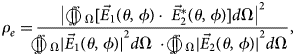
To support the MIMO capability of the proposed antenna, important diversity parameters envelope correlation coefficient (ECC), diversity gain (DG), and channel capacity loss (CCL) are analyzed as explained in [Reference Biswas and Chakraborty16, Reference Dingliang, Yang, Max and Hanyang18]. ECC signifies the correlation of antenna radiation pattern with another antenna when operated in closed proximity. The high value of ECC degrades the antenna MIMO performance. ECC value lower than 0.5 is acceptable for MIMO antennas. ECC is calculated using the 3D radiation pattern as
where $\vec{E}_1\lpar {\theta \comma \;\phi } \rpar$ and $\;\vec{E}_2^\ast \lpar {\theta \comma \;\phi } \rpar$
 are the far fields of antenna for radiator 1 and radiator 2.
DG shows the accomplishment of diversity performance of MIMO antenna and it can be evaluated using ECC.

Simulated and measured ECC and DG plots are shown in Fig. 17. It can be observed that ECC results are well below 0.025 and DG is more than 9.8 dB for 2.4–2.48 GHz.
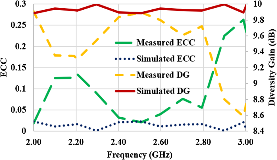
Fig. 17. ECC and DG of the proposed antenna.
CCL limits the data transmission rate over the channel. The low value of CCL ensures higher data rate. The value of CCL should be <0.4 bits/s/Hz for a MIMO system. CCL can be evaluated as
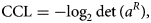
where a R is the 2 × 2 correlation matrix and its elements are given as $a_{ii} = 1-\lpar {{\vert {S_{ii}} \vert }^2 + {\vert {S_{ij}} \vert }^2} \rpar \semicolon \;a_{ij} = 1-\lpar {S_{ii}^\ast S_{ij} + S_{ji}^\ast S_{jj}} \rpar$ .
.
Measured and simulated CCL are shown in Fig. 18. The proposed structure has <0.12 bits/s/Hz value of CCL at ISM band.

Fig. 18. Plot for channel capacity loss (CCL).
Conclusion
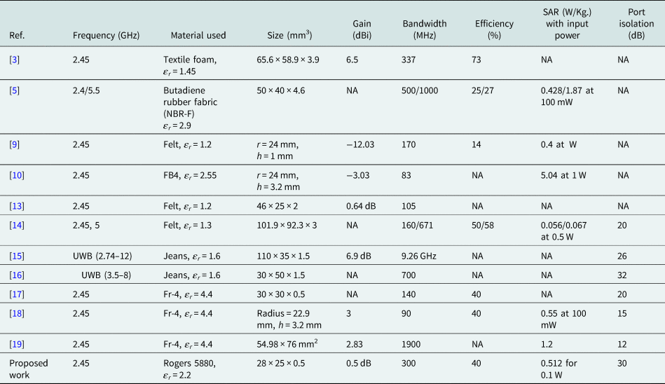
We have demonstrated a MIMO antenna structure for on-body communication. A prototype covering 2.45 GHz band is designed, fabricated, and its performance is measured on pork loin. The proposed MIMO structure has an overall dimension of 28 × 25 × 0.51 mm3. The wide bandwidth of 300 MHz is suitable to maintain a robust communication link when operated in a different biological environment. Improved port isolation of 30 dB and a good diversity performance are obtained. Stable performance is obtained when the antenna is subjected to structural deformation. Low SAR value of 0.512 W/Kg ensures the user's safety. Antenna performance is compared with the existing single-element and MIMO-based on-body antennas in Table 2. The proposed structure is the smallest of all the antennas compared in Table 2 with satisfactory on-body as well as diversity performance.
Table 2. Comparison of the proposed antenna with the existing on-body antennas
 Anupma Gupta received her B.Tech degree in Electronics and Communication Engineering from Guru Jambheshwar University, India, in 2006 and M.Tech degree from Maharishi Markandeshwar University, Mullana, India, in 2010. She is currently working toward the Ph.D. degree at Thapar University. Her main research interests are the design and optimization of microstrip antennas, biomedical telemetry, and electromagnetics.
 Ankush Kansal received his B.Tech. and M.Tech. degree in Electronics and Communication Engineering from PTU, Jalandhar and the Ph.D. degree from Thapar University, Patiala in the area of Wireless Communication. He is currently working as an Assistant Professor at Thapar University, Patiala. He has published 25 research articles in referred international journals, international conference, and national conference. He is a lifetime member of ISTE. His research interests include networking, wireless communication, image processing, and embedded systems.
 Paras Chawla received his B.Tech (Honors) and M.Tech degree in Electronics and Communication Engineering from Kurukshetra University, NIT, Kurukshetra and the Ph.D. degree from Thapar University, Patiala. He has more than 14 years of teaching experience and currently working as a Professor and HOD in the ECE Department at Chandigarh University, Mohali (India). He guided a total of 16 M.Tech dissertations successfully and also guiding seven students of the Ph.D. degree. He received the “Coventor Scholarship award” from MANCEF, New Mexico, USA for his proposal in the conference COMS-2010. His team received consecutively 2 years the “Tenderfoot Award” collaboratively given by American Astronautical Society and American Institute of Aeronautics, for “CanSat Competition”, June 2015 and 2016, Burkett, Texas, USA. His main research interests include microstrip antennas, RF MEMS, RF front-end mobile terminal, LTE, and 5G. He has published more than 50 papers in various reputed national and international journals/conferences, one SCI book chapter, and 10 patents filed.


