I. INTRODUCTION
Electronically scanned arrays (ESAs) have been used in a vast amount of applications, where there is the need to electronically point the radiated beam, ranging from commercial and defense ground and satellite systems to radar/electronic warfare, sensors, and RFIDs [Reference Hansen1–Reference Finkenzeller6]. Their ability to electronically point (and scan) the directive radiated beam in various directions in space is due to the use of multiport beam-forming networks (BFNs). BFNs provide the appropriate amplitude and phase distributions to the antenna array, in order to shape the desired radiation pattern and steer the main lobe to different angular directions in space. One special category of ESAs is the multiple beam antennas (MBAs), where the BFN is consisted of a multiple input–multiple output (MIMO) network configuration. In such systems, the radiated beam is pointed in predefined stepped angular directions, usually through the switched sequential excitation of the network's input ports.
One of the most popular BFNs is the well-known Butler matrix [Reference Hansen1–Reference Lo and Lee3, Reference Butler and Lowe7–Reference Pattan12]. The Butler matrix has been widely used in ESAs as a MIMO BFN. Its versatility and simplicity has made it the major choice for MBAs. It is a passive and reciprocal analog microwave network, comprised of hybrid couplers and phase shifters. From a circuit point of view it is the analog equivalent of fast Fourier transform (FFT). Usually, the number N of its input and output ports is a power of 2 (N = 2n). The output ports are connected to the array antenna terminals. Each input port excitation produces a uniform amplitude distribution and a unique phase distribution at the outputs, pointing the radiated beam at a different direction in space. For a continuous scanning, the input ports are sequentially excited one by one, with the use of an electronic switch.
Owing to its passive and theoretically lossless nature and its low complexity (FFT equivalent), the Butler matrix has been used in a variety of applications. However, its major drawback is its inability to produce tapered output amplitude distributions, which lead to low sidelobe level (SLL) radiation patterns. That is, if the matrix feeds a linear antenna array, the array factor (AF) has a minimum value of SLL equal to about −13.2 dB, [Reference Hansen1]. Thus, it is not a satisfactory choice for systems where the SLL is of essential importance and must be relatively low. A solution to this problem was proposed by the pioneers of the Butler matrix in [Reference Butler and Lowe7, Reference Shelton9], suggesting the use of additional circuitry (unequal hybrid 180o couplers or power dividers with phase shifters) at the output terminals. This approach has been applied in [Reference Gruszczynski, Wincza and Sachse13, Reference Li14]. Nevertheless, this solution imposes the increase of the number of radiating elements in the array. Another classic solution is the simultaneous excitation of multiple input ports [Reference Mailloux2, Reference Bhattacharyya5, Reference Skolnik15–Reference Gotsis, Kyriacou and Sahalos18]. Specifically, if a pair of input ports is simultaneously excited, a cosine distribution is produced at the outputs, offering an SLL equal to −23 dB. The technique can be further applied to three input ports, producing a cosine squared on a pedestal distribution and offering an impressive minimum SLL of −43 dB [Reference Mailloux2]. In our previous work [Reference Fakoukakis and Kyriacou17, Reference Gotsis, Kyriacou and Sahalos18] the former technique is analyzed and applied to an 8 × 8 Butler matrix at a numerical simulation level. Prototypes are now fabricated and the respective design methodology is validated through measurements. Other methods make use of attenuators, connected between the output ports and the antenna array terminals [Reference Gruszczynski, Wincza and Sachse13, Reference DuFort19, Reference DuFort20]. On the other hand, only a handful of design approaches on low SLL modified Butler-like matrices has been presented [Reference Fragola, Orefice and Pirola21, Reference Fakoukakis, Kyriacou and Sahalos22]. These techniques adopt a matrix modification procedure, in order to be able to produce tapered amplitude distributions without the use of additional input or output circuitry.
In this work, an example of the simultaneous excitation of a pair of input ports is presented in the first part. Moreover, the switched line-phase shifter (SLPS) technique [Reference Fakoukakis and Kyriacou17, Reference Gotsis, Kyriacou and Sahalos18] is applied, in order to increase the number of radiated beams and enhance coverage without increasing the matrix order. However, the emphasis is given on the second part, where some novel modified Butler matrix architectures are introduced, creating tapered amplitude distributions under single port excitation and thus, avoiding the complexity of additional circuits. Presented modified designs offer SLLs well below −25 dB.
II. SIMULTANEOUS INPUT PORTS EXCITATION
A) Network design
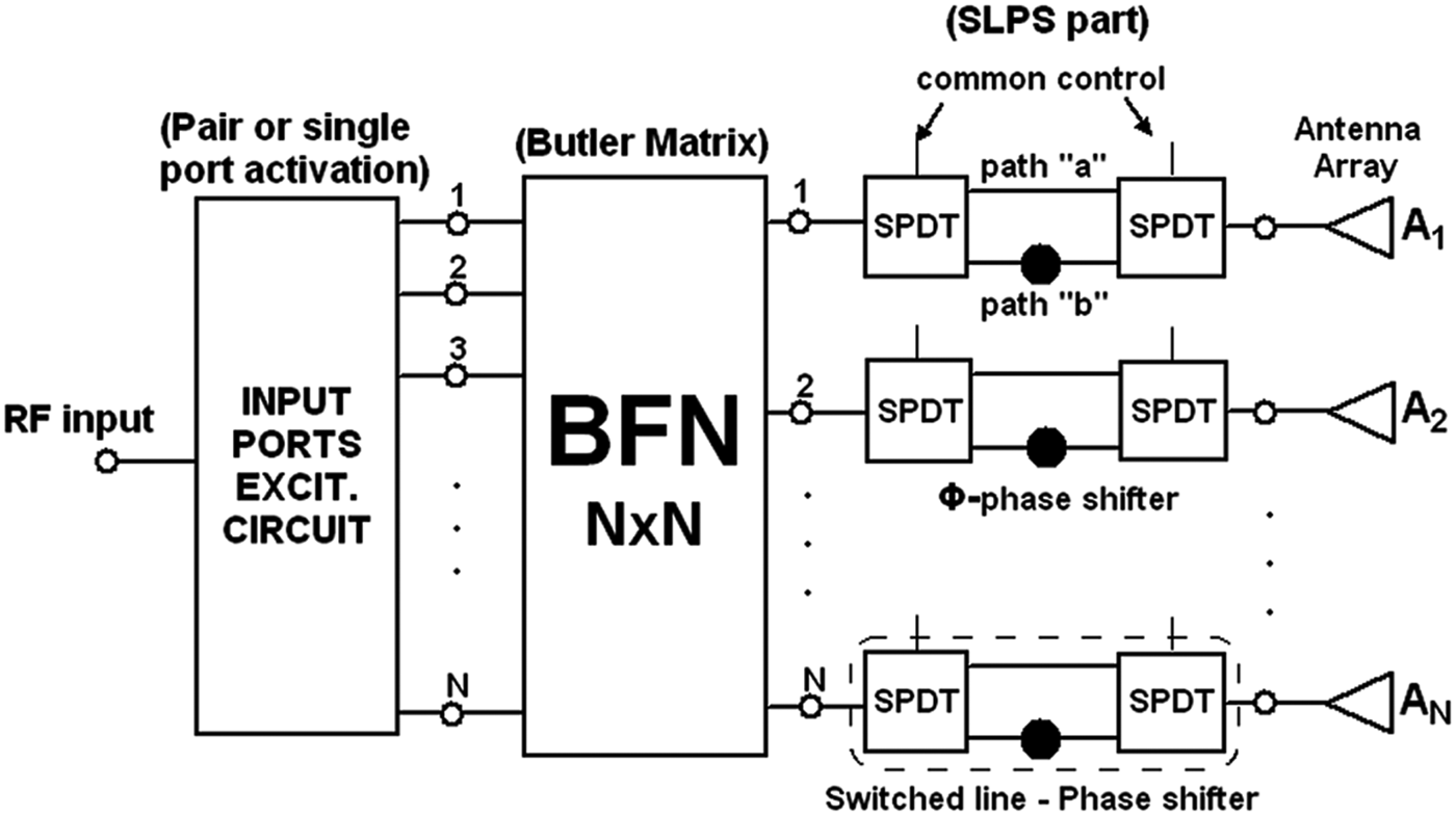
As mentioned above, the simultaneous excitation of multiple input ports was one of the very first methods to decrease the SLL of a Butler matrix-fed antenna array. In most cases, only a pair of input ports are simultaneously excited, leading to a cosine amplitude distribution at the output (antenna) ports and offering a −23 dB SLL [Reference Mailloux2, Reference Bhattacharyya5, Reference Skolnik15–Reference Gotsis, Kyriacou and Sahalos18]. Herein, this technique is used for the design of a BFN feeding a linear eight-element patch antenna array in the 2.4 GHz ISM band. The schematic diagram for the general case (N × N ports) of the complete system is shown in Fig. 1.

Fig. 1. Schematic diagram of the simultaneous input ports pair excitation system.
The basic building block of the system in Fig. 1 is an 8 × 8 Butler matrix. Its input ports are connected to the input ports excitation circuit, which provides the simultaneous excitation to the appropriate pair of ports at each time. Such a circuit can be designed using a set of power dividers, power combiners and phase shifters [Reference Bhattacharyya5] or a power divider with a switching matrix [Reference Siachalou16–Reference Gotsis, Kyriacou and Sahalos18]. In this work, a modification of the second approach is used.
Explicitly, the input port excitation circuit can activate any pair of input ports (corresponding to spatially successive beams) or one of the eight single ports, under electronic control. This design choice makes feasible the creation of both low SLL (−23 dB) and standard (−13.2 dB) Butler matrix beams, according to the system or user demands. For example, in some transmit/receive systems, low SLL beams are needed in the transmit mode, whereas standard beams can be used during receipt. Moreover, the SLPSs can be commutated electronically to the two alternative paths “a” and “b” providing two distinct phase sequences, as described explicitly in our previous work [Reference Fakoukakis and Kyriacou17]. The “a” paths offer the eight conventional orthogonal beams from an excitation phase sequence of (±22.5°, ±67.5°, ±112.5°, ±157.5°), whereas the “b” paths enable for a second group of seven new orthogonal beams from an excitation phase sequence of (0°, ±45°, ±90°, ±135°). Hence, the implementation of the SLPS technique increases the number of radiated beams and improves sector coverage quality through the creation of a densified beam cluster. A similar approach with tunable phase shifters has been used in [Reference Chang, Lee and Shih23], however, without the use of a low SLL Butler matrix-based beamformer.
B) Fabrication and measured results
The layout of the fabricated microstrip 8 × 8 Butler matrix prototype is shown in Fig. 2. The network was developed on a ROGERS 4003C substrate, with a dielectric constant ε r = 3.38, thickness h = 0.508 mm and loss tangent tanδ = 0.0021. Design frequency was set at 2.45 GHz (ISM band), whereas design and simulations were performed using Agilent ADS and Momentum. Figure 3 shows the measured return loss of the matrix input ports, which is kept below −15 dB for the largest part of the bandwidth (2.4–2.48 GHz).
Fig. 2. Layout of the fabricated uniform output distribution 8 × 8 Butler matrix prototype.
Fig. 3. Measured return loss of the uniform output distribution Butler matrix input ports.
Respectively, Fig. 4 presents two characteristic examples of the measured transmission coefficients towards antenna elements, for the cases of 1L and 3R input ports excitation. Ideal theoretical value is −9 dB, whereas measured results are between −10 and −12.5 dB, for the most cases. Note that the lower values are due to the losses of the relatively long paths between inputs and outputs. However, what is important is for the power at the output ports and correspondingly the transmission coefficients to be equal (uniform array distribution). From this point of view, indeed the measured transmission coefficients of Fig. 4 present an average value of −11 dB with a ±1 dB deviation and thus, an average loss of 2 dB. Similar results were acquired for the rest of the input ports. These losses (about 2 dB average) and deviations are considered acceptable, taking into account network's size and thus, the results are satisfactory.
Fig. 4. Measured transmission coefficients towards antenna elements for the uniform output distribution (about −11 dB) 8 × 8 Butler matrix. (a) 1L input port excitation, (b) 3R input port excitation.
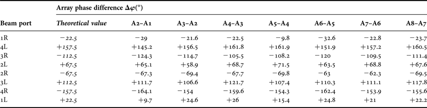
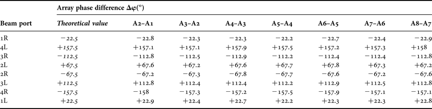
Based on the measured results of return loss and transmission coefficients, best performance was observed at about 2.425 GHz. Table 1 presents the measured phase differences between antenna ports, for all input ports excitation cases at 2.425 GHz.
Table 1. Measured phase differences between antenna ports for the uniform output distribution 8 × 8 Butler matrix.
In order to have an estimate of the complete system performance, as it is presented in Fig. 1, simulations using the measured S-parameters were performed. Specifically, the measured S-parameters of the Butler matrix prototype were used in a data file, along with the measured S-parameters files of the switching devices that were chosen. Thus, the complete system was modeled using measured S-parameters files of each of the building blocks (Butler matrix, input ports excitation circuit and SLPSs). The resulting simulated S-parameters were imported in an antenna simulation tool as input data and utilized as the antenna array amplitude and phase excitation coefficients. The simulated radiation patterns include the seven low SLL beams produced by the pair excitation technique ((1L, 1R), (1R, 2R), etc.), along with six new low SLL beams produced by using the SLPSs in addition to the pair excitation ((1L, 1R) +, (1R, 2R) +, etc). The results, for an inter-element distance d = λ o/2 at f = 2.425 GHz, are shown in Fig. 5(b), whereas, in order to compare, Fig. 5(a) shows the simulated radiation patterns produced by the theoretical values of amplitude and phase distributions at f = 2.45 GHz. Firstly, as it can be observed, the patch radiation pattern imposes a degradation to the array pattern. As a result, the far outermost beams present maximum values lower than the limit value of −3 dB. However, the crossover level (CL) is at about −1 dB, improving critically the scanning effectiveness. Lastly, as it is easily observed, beam orthogonality is cancelled, due to beam widening, which is also responsible for the increase in CL. Moreover, in order to compare the results with the corresponding theoretical ones, it is observed that the deviations in the measured phase differences with respect to their theoretical values (Table 1) yield negligible shift in the beam maximum pointing. However, the corresponding transmission coefficients deviations (Fig. 4) although less than 2.5 dB, cause significant changes in the excitation amplitude distributions. This is reflected to a significant degradation of the overall SLL, from about −24 dB in the theoretical case of Fig. 5(a) to values up to −17 dB in the beams resulting from measured results (Fig. 5(b)). But, the SLL of −17 dB constitutes a significant improvement over the value of about −10 dB obtained from conventional Butler matrices implementing uniform amplitude excitations.
Fig. 5. Simulated radiation patterns of the complete system (Fig. 1) for d = λ o/2. (a) Using theoretical distribution data at f = 2.45 GHz, (b) Using measured S-parameters data, at f = 2.425 GHz.
Concluding this section, a switched beam phased array system with high spatial resolution and an SLL better than −17 dB, is achieved. However, its main drawback refers to the complexity and cost of the additional circuits regarding the input ports pair activation. Moreover, a variety of important applications (e.g. Radar/EW/SIGINT) require far lower SLLs of better than −20 dB or even more. One solution refers to simultaneously activating three or four Butler matrix input ports, but this results to a non-affordable circuit complexity, surpassing that of the Butler matrix itself. Noting that BFNs in the class of the 8 × 8 Butler matrix involve some unavoidable microwave losses of about 2 dB (Fig. 4), these must be balanced with the aid of amplifiers (HPAs/LNAs). In view of this reality it is worthy to elaborate on the alternative advantageous solution of simpler lossy BFNs in order to realize tapered amplitude/power antenna excitation distributions. The corresponding type of network elaborated in the next section is built as a lossy modification of the conventional Butler matrix.
III. MODIFIED ASYMMETRIC BUTLER MATRIX
Whenever one employs lossy networks, system's efficiency must be carefully considered. It is strongly stated in the literature [Reference DuFort19, Reference DuFort20, Reference Allen24–Reference Stein26] that low SLL networks suffer from relatively increased losses (and beam orthogonality destruction), due to the creation of tapered amplitude/power distributions, which can generally exceed 3 dB. Specifically, a loss value of 3 dB should be considered as a standard [Reference DuFort19]. Thus, the efficiency should be expected to be lower than 50%. In [Reference DuFort19] it is stated that the maximum efficiency possible in tapered amplitude/power distribution networks is defined as the ratio of the average to the peak value of the aperture power distribution. According to the above definition, the theoretical maximum efficiency of the system presented in Section II (for the predefined cosine distribution and the SLL of −23 dB) is about 52%. However, measured data, which include real system losses, give an average value of efficiency equal to about 40%, for all the 13 beams. Both results are considered acceptable. Moreover, since high losses and reduced efficiency is a standard in low SLL networks, these disadvantages must be balanced in all modern systems by the use of HPAs/LNAs in the final design, in order to maintain satisfactory performance. However, this solution itself also implies constraints, since it involves higher values of consumption, dissipative elements, higher cost and increased volume. Thus, the designer must make careful choices and compensations in order to achieve maximum efficiency with maximum system performance.
Besides the above, it must be noted that for the following asymmetric BFNs the convenient beam switching and the reciprocal properties of the Butler matrix are retained, while the introduction of losses still destroys beam orthogonality (due to beamwidth widening). On the other hand, beamwidth widening results to an increase in the CL of the adjacent beams. Generally, increased losses are allowed (more than 3 dB) and beam orthogonality is sacrificed. The above circuit characteristics are in agreement with the well-established theory of lossy low SLL multi-beam networks presented in previous related works [Reference DuFort19, Reference DuFort20, Reference Allen24–Reference Stein26]. Overall, these sacrifices are made in order to avoid system complexity, while achieving the desired SLL improvement.
A) Lossy Butler BFN design review
In order to achieve tapered amplitude distributions from a Butler matrix network without the use of external additional circuitry, while keeping single port excitation, circuit architecture modifications must take place. The basic alteration in network topology is the substitution of standard 3 dB couplers with equivalent coupler/divider circuits with unequal power distribution, [Reference Fragola, Orefice and Pirola21, Reference Fakoukakis, Kyriacou and Sahalos22]. A similar, but improved approach is adopted herein, while beyond that, the resulting beamformer is fabricated and tested.
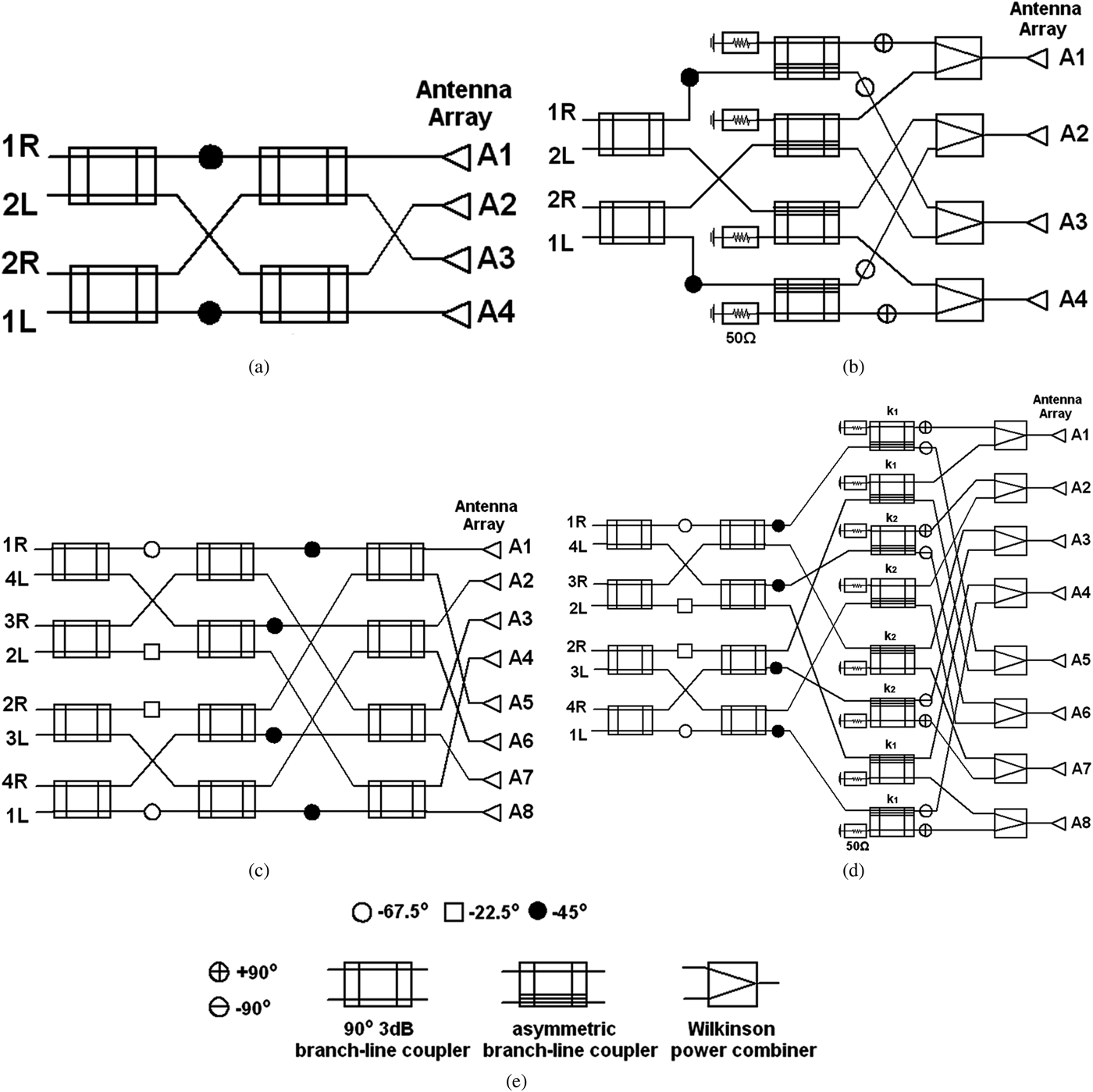
The design idea that is proposed herein is presented schematically in Fig. 6, where the schematic diagrams of standard and modified 4 × 4 and 8 × 8 low SLL Butler matrices are shown, respectively. The basic feature of the design novelty is that the last column 3 dB hybrid couplers (feeding the antenna elements) are replaced with a phase equivalent unequal power distribution circuit, comprised of asymmetric couplers, phase shifters and Wilkinson power combiners. Each substituted 3 dB coupler is replaced with two asymmetric ones, where the fourth port of each remains unused and is terminated to a 50 Ω load. Phase shifters are used, in order to preserve the phase distribution, whereas the Wilkinson combiners are needed to combine signals from different paths, feeding the same antenna element. Thus, the novel modified architectures presented in Figs 6(b) and 6(d) are able to produce tapered amplitude distributions under standard single port excitation of Butler matrix input ports. The demanded amplitude distribution can be formed with the proper design of the asymmetric hybrid couplers. Despite the obvious increase in size, compared to the equivalent standard matrix, the basic advantage of the proposed architecture is the avoidance of additional circuits and retaining reciprocal operation. Additional circuits increase complexity, cost and size even more, while can have a higher impact on network's losses/efficiency or even reciprocity (when not using T/R diodes/switches). Moreover, the original number and angular pointing of beams of the conventional Butler matrix are preserved. Furthermore, in terms of the amplitude distribution formation, the simultaneous excitation produces only cosine-type distributions, whereas the proposed architecture can theoretically form any arbitrary distribution. The only occasion where this is not always the case is in networks with order higher than 4, due to limitations in the power division ratios of the asymmetric couplers imposed by the conservation of energy and not by their inability to divide power in accordance to the demanded ratios.
Fig. 6. Schematic diagrams of standard and modified Butler matrices. (a) standard 4 × 4 matrix, (b) modified low SLL 4 × 4 matrix, (c) standard 8 × 8 matrix, (d) modified low SLL 8 × 8 matrix, and (e) symbols for the associated symmetric/asymmetric branch-line couplers, power combiners and phase shifters.
It must be noted that a similar circuit architecture using unequal Wilkinson power dividers was proposed in our previous work [Reference Fakoukakis, Kyriacou and Sahalos22]. However, conventional Wilkinson divider circuits cannot offer high values of power division ratios, especially due to constraints in the fabrication of high impedance microstrip lines. Similar disadvantages can be observed in the approach used by Fragola et al. in [Reference Fragola, Orefice and Pirola21], where the design of asymmetric couplers was performed using the conventional technique of altering the characteristic impedances of the longitudinal and transverse branches of the branch line coupler. This design technique also suffers from limitations in the maximum achievable power division ratio value, since large alterations in the characteristic impedances of the branches, which lead to high values of output power division ratios, cause critical deterioration of input return loss and port isolation. Besides that, high division ratios in a hybrid coupler ask for high characteristic impedances for its branches, corresponding to very narrow microstrip lines which usually exceed the fabrication limits, causing inaccuracies and power limitations. Thus, in this work the above drawbacks and limitations are surpassed with the choice of proper asymmetric couplers, which make feasible the design of antenna arrays with extremely low SLLs.
In that way, keeping the proposed architecture as the design basis, there is a versatility in selecting the type of asymmetric couplers that can be used. Herein, a novel branch line asymmetric coupler was exploited, as it was proposed in [Reference Kim27], since it offers an ease in the design and can produce extremely high values of unequal power division ratios. Other types of unequal hybrid couplers can be also used, such as the one produced by the cascaded connection of two 3 dB hybrids [Reference Cummings28–Reference Fakoukakis and Kyriacou30].
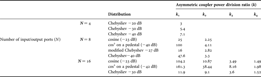
As an example of the high values of unequal power division ratios needed in low SLL distributions, Table 2 lists the values of unequal power division ratios of the asymmetric couplers needed to produce different amplitude distributions, for different numbers of matrix input/output ports N.
Table 2. Example list of asymmetric coupler power division ratios needed for different amplitude distributions and number of matrix input/output ports (N).
Furthermore, the design method can be extended to higher order matrices (16 × 16, 32 × 32, etc.), but with the associated increase in size and complexity. Apart from all the above, the SLPS technique can be independently applied as described in Section II, in order to increase the number of radiated beams.
B) Modified 4 × 4 Butler matrix fabrication and measurements
The proposed design idea was verified through fabrication and measurements of circuit prototypes. Figure 7 shows the photograph of a fabricated microstrip modified 4 × 4 Butler matrix, designed to produce a −30 dB Chebyshev amplitude distribution. The network was designed in the S-band (2–4 GHz), with a central frequency of 3 GHz, on a Rogers4003C substrate with dielectric constant ε r = 3.38, thickness h = 0.508 mm and loss tangent tanδ = 0.0021. The asymmetric couplers were designed to produce an output power division ratio of 5.4:1, needed to create the chosen Chebyshev distribution.
Fig. 7. Fabricated microstrip prototype of the modified 4 × 4 Butler matrix, according to Fig. 6 (b), for a −30 dB Chebyshev distribution.
Figure 8 shows the measured S-parameters results of the input ports return loss and isolation, whereas Fig. 9 presents the measured results of the transmission coefficients towards antenna elements, for the characteristic excitation cases of 1R and 2L input ports, respectively. It can be observed from Fig. 8(a) that measured return loss is kept below −13 dB at the central frequency of 3 GHz, while 2R and 2L ports have a value below −20 dB. Similarly, isolation between input ports is below −20 dB at the central frequency. Moreover, transmission coefficients results in Fig. 9 are also satisfying, preserving the Chebyshev distribution. Ideal theoretical values are −6.8 dB for the central (A2,A3) and −14.1 dB for the edge (A1,A4) elements, whereas losses range from 0.6 dB to about 2.5 dB, especially for the 2L input port excitation case. Similar results were observed for the 1L and 2R input ports.
Fig. 8. Measured results of the modified 4 × 4 Butler matrix. (a) Input ports return loss, (b) isolation between input ports.
Fig. 9. Measured transmission coefficients magnitudes toward antenna elements for the modified 4 × 4 Butler matrix. (a) 1R input port excitation, (b) 2L input port excitation.
Measured results (Figs 8 and 9) show satisfactory performance for the studied bandwidth of 400 MHz around the central frequency of 3 GHz, except from the 2R and 2L input ports return loss, which is higher than −10 dB beyond 3.1 GHz (Fig. 8(a)). Moreover, the phase of measured transmission coefficients showed best performance at 2.965 GHz. Thus, since phase differences are critical for the beam steering and exploiting the fact that measured return loss, isolation and transmission coefficients magnitudes are kept satisfactory at that frequency, simulated radiation patterns will be presented at the optimum operational frequency of 2.965 GHz. However, it must be noted that circuit performance still remains acceptable inside a bandwidth of about 200 MHz around central frequency (2.9 GHz–3.1 GHz).
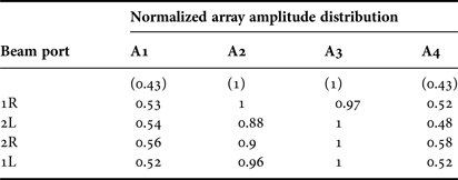
Table 3 lists the normalized amplitude distribution, extracted from measured transmission coefficients magnitudes at 2.965 GHz. Ideal theoretical values are in parentheses. Respectively, Table 4 shows the measured phase differences between antenna elements at the same frequency, giving best results over bandwidth of interest. Finally, Fig. 10(a) shows the simulated radiation patterns using theoretical weightings at f = 3 GHz, whereas Fig. 10(b) presents the simulated radiation patterns using measured S-parameters data (transmission coefficients), at the frequency of 2.965 GHz. It must be noted that the inter-element distance (d) is set at 2λ o/5(=0.40λ o), in order to prevent the appearance of grating lobes. The results in Fig. 10(b) are satisfying, especially for the 1R and 1L beams. Amplitude and phase inconsistencies, which are larger for the edge 2R and 2L beams, produce higher than expected sidelobe values and not very sharp nulls. Specifically, it is observed that the phase deviations in the experimental results as high as 20° (A4–A3) do not significantly affect the beam maximum directions, but they have a non-trivial impact on null shaping. Moreover, the corresponding amplitude deviations of about 1 dB degrade the SLL of the outer beams (Fig. 10(b)) by a significant amount of 13 dB (from less than −30 dB to as high as −17 dB), with respect to its theoretical value (Fig. 10(a)), but it still remains lower than the SLL achieved by a conventional Butler matrix (up to −10 dB). Considering all the above, the general idea of designing a low SLL Butler matrix is verified.
Fig. 10. Simulated radiation patterns of the modified 4 × 4 Butler matrix for d = 2λ o/5. (a) Using theoretical amplitude and phase weighting at f = 3 GHz, (b) using measured transmission coefficients, at f = 2.965 GHz.
Table 3. Measured normalized array amplitude distribution of the modified 4 × 4 matrix.
Table 4. Measured array phase differences of the modified 4 × 4 matrix.
As far as the efficiency of the network is concerned, the definition of the theoretical maximum using power distribution data gives a value of 51.7%. However, due to the use of the Wilkinson power combiners, which add a 3 dB loss, network's efficiency cannot be better than 50%. Thus, the real value of efficiency is extracted using S-parameters data. Simulations using ideal components gave a value of 49.6%, which constitutes the true maximum value. Measured results gave an average value of 32.2%, for all input ports excitation cases (or correspondingly, radiated beams). Despite the fact that efficiency may seem relatively low, such values are not unusual, since low SLL networks present relatively large losses. Although, this problem can be solved in modern systems with the use of high-power amplifiers at the input port level or at the antenna level using active antenna array configurations, while keeping in mind the constraints referred earlier.
C) Modified 8 × 8 Butler matrix design and simulation
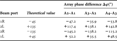
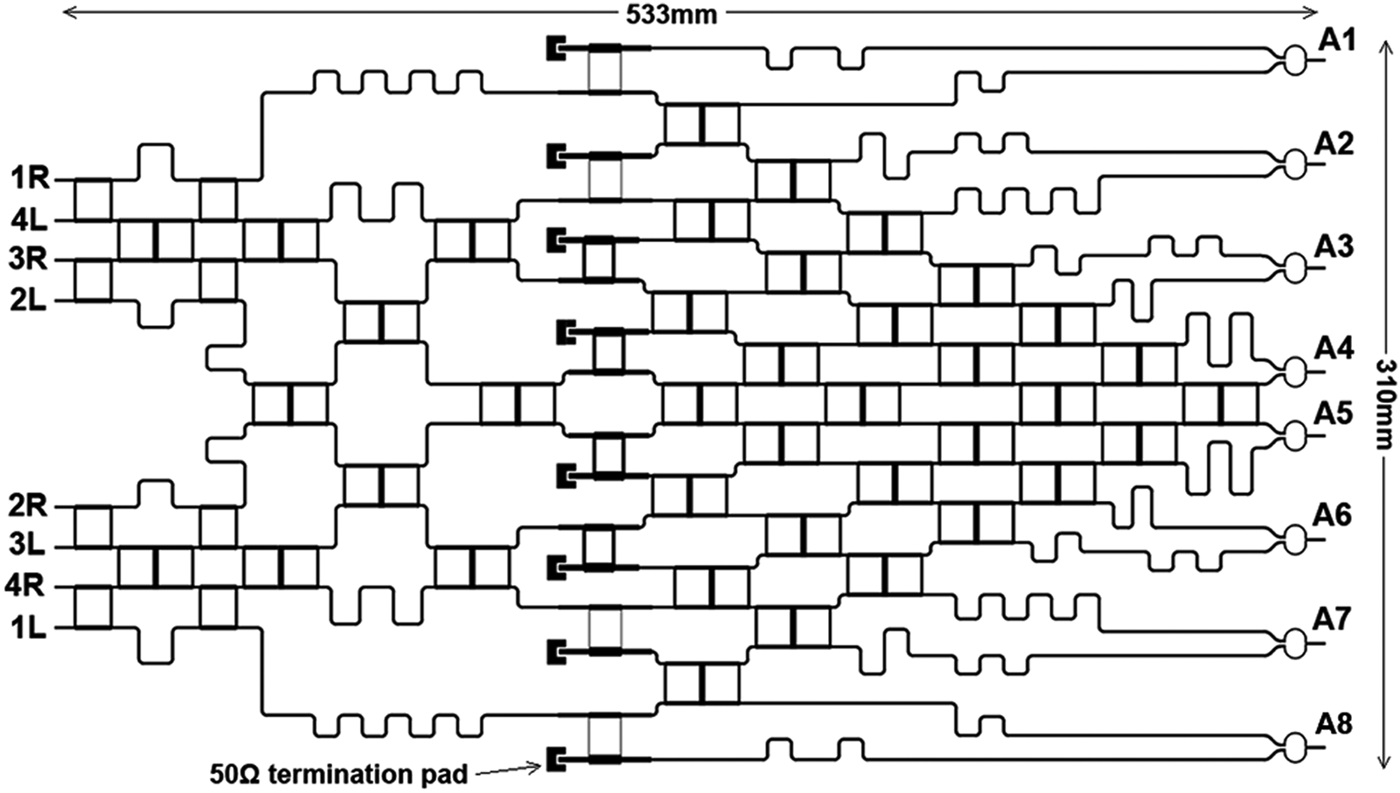
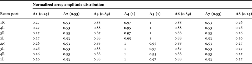
A modified 8 × 8 Butler matrix was also designed at 3 GHz, exploiting the same technique and using the architecture shown in Fig. 6(d). A modified −27 dB Chebyshev distribution was chosen, due to the limitations related to the conservation of energy, as referred earlier. Two different values of power division ratios are now needed; the first must be equal to 16:1 and the second equal to 2.82:1. As previously mentioned, the selected coupler topology can easily produce high values of power division ratios such as the ones needed in very low SLL distributions. The microstrip layout of the network is shown in Fig. 11. Table 5 shows the simulated normalized amplitude distribution, along with the ideal values, whereas Table 6 lists the simulated array phase differences produced by input ports excitation.
Fig. 11. Microstrip layout of the modified 8 × 8 Butler matrix.
Table 5. Simulated normalized array amplitude distribution of the modified 8 × 8 matrix.
Table 6. Simulated array phase differences of the modified 8 × 8 matrix.
Efficiency calculations gave a true maximum value of 49.8%, using ideal components during simulation. On the other hand, the use of real-world components, including microstrip losses and discontinuities along with substrates losses, gave an average value of efficiency equal to 31%, for all input ports excitation cases.
The data presented in Tables 5 and 6 (extracted from simulated S-parameters) were used to produce the array radiation patterns. Inter-element distance (d) was again chosen properly in order to reduce the grating lobe level and was set at 17λ o/40(=0.425λ o). Figure 12 shows the produced low SLL beam cluster. The superior performance of the simulated 8 × 8 BFN (Fig. 12) over its 4 × 4 counterpart (Fig. 10) is obvious. The reason can be clearly observed by comparing the amplitude distributions of Tables 3 and 5, where the maximum deviation from the desired values is 35 and 8%, respectively. Hence, the problem is located in achieving the desired power divisions. The simulated versus measured disagreements can be attributed to some inability in transferring the design to fabricated printed networks or lack of modeling some parasitic in the asymmetric couplers.
Fig. 12. Simulated radiation patterns using simulated transmission coefficients of the modified 8 × 8 Butler matrix, for d = 17λ o/40.
Despite the size of the network, which usually imposes non-trivial losses and amplitude and phase deviations, the results of Fig. 12 are considered quite satisfying. All SLLs are below −23 dB, whereas nulls are also sharp enough. Lastly, as far as the degradation of the outermost beams is concerned, in cases where it cannot be considered acceptable and/or cannot be corrected with amplification, they can be excluded from use, with a price in the total sector angular width.
IV. DESIGN APPROACHES COMPARISON
As a comparative discussion about the two design approaches, the first attribute that must be emphasized is the amount of system complexity and cost introduced by the simultaneous excitation technique. Apart from that, the SLL that can be achieved is very specific, no matter how many ports are simultaneously activated. Moreover, the beam number and angular position of the conventional Butler matrix are not preserved. On the other hand, the modified lossy Butler matrix method avoids additional circuitry and offers increased flexibility in choosing the amplitude distribution and thus, the SLL that can be achieved. Furthermore, the beam number and angular position of the standard Butler matrix are maintained. However, someone could argue about the efficiency of these types of networks and specifically, if comparing it with a simultaneous port excitation system, as presented herein. Both modified designs presented lower values of efficiency (either measured or simulated) than the system using the simultaneous excitation method. In other words, the losses are larger in such types of networks. But, relatively increased losses and average values of efficiency are a precondition in low SLL multi-beam networks. This disadvantage can be overcome by active antenna configurations, employed in almost every modern system, but with careful design choices, in order to compensate the increased consumption and cost of active configurations. Thus, the proposed novel design architecture presents an overall improved operation compared to the simultaneous port excitation approach and could constitute a major choice for low SLL multi-beam and ESA systems.
V. CONCLUSION
Two different approaches on the design of low SLL Butler matrix-based ESAs were presented. The conventional technique of simultaneous input port excitation was verified and evaluated. The SLPS technique was additionally applied in order to increase the number of radiated beams. However, the emphasis was given on a novel technique on the design of modified low SLL Butler matrices, offering comparative advantages to previous methods, such as circuit simplicity and flexibility in the amplitude distribution formation. The general design idea was given, along with some characteristic examples. Network prototypes were fabricated and tested, giving satisfactory results and verifying the proposed architecture. Future work includes the extension of the design idea to higher-order networks and methods to minimize size and increase bandwidth.
ACKNOWLEDGEMENTS
This research has been co-financed by the European Union (European Social Fund-ESF) and Greek national funds through the Operational Program “Education and Lifelong Learning” of the National Strategic Reference Framework (NSRF) – Research Funding Program: THALES. Investing in knowledge society through the European Social Fund.
Fanourios E. Fakoukakis received a Diploma and an M.Eng. in Electrical and Computer Engineering from Democritus University of Thrace in 2003 and 2005, respectively. He is currently a Ph.D. student at the same university. He was a research associate at the Institute of Electronic Structure and Laser, FORTH, Greece. He has been a laboratory and teaching associate at the Technological Educational Institute of Crete since 2008. His main research interests are beam-forming networks, antennas, microwave circuits, and antenna arrays.
 Theodoros N. Kaifas received a Ph.D. degree from the Department of Physics, Aristotle University of Thessaloniki, in 2004. From 1993 to 2004, he was a Research Assistant, from 2004 to 2006, a Postdoctoral Research Fellow, and since 2006, has been a Senior Research Associate with the Radio Communications Laboratory (RCL), Department of Physics, AUTH. During 2001–2008, he was an Adjunct Professor with the Department of Electronics, Technological Educational Institute of Thessaloniki, Greece; and during 2006–2007, with the Department of Technology Management, University of Macedonia, Greece. Since 2004, he has been an Adjunct Professor for the Program of Postgraduate Studies in Electronic Physics (Radioelectrology), AUTH. His research interests are wireless communications; satellite communications; RF/microwave circuits; antenna analysis and design; and computational methods in electromagnetics. Dr. Kaifas is a member of the Hellenic Physicist Union, the Hellenic Club of Electronic Physicists and a senior member of the IEEE.
Elias E. Vafiadis received a B.Sc. degree in Physics and an M.Sc. degree in Electronic Physics from Aristotle University of Thessaloniki in 1975 and 1979, respectively. He received his Ph.D. in Electrical and Electronic Engineering from Democritus University of Thrace in 1985. He was a Lecturer and an Assistant Professor in the Department of Electrical and Computer Engineering, Democritus University of Thrace. He has been an Associate Professor in Aristotle University of Thessaloniki since 2004. His current research interests focus on the development of RF/RFID systems and on innovative design techniques for broadband wireless networks, and for digitally controlled RF and microwave structures. He has published nearly 85 peer-reviewed scientific papers and has served as principal investigator in 28 research projects financed from industry, the EU and ESA.
 George A. Kyriacou received a Diploma in Electrical Engineering and a Ph.D. degree, both with honors, from Democritus University of Thrace in 1984 and 1988, respectively. He is now a Full Professor and Deputy Director in the Electrical and Computer Engineering Department, DUTH, and Director of the Microwaves Laboratory. He has published more than 150 peer-reviewed articles in scientific journals and conference proceedings. His research interests are microwave engineering, antennas, applied and computational electromagnetics and biomedical engineering. He is a senior member of IEEE and a Fellow of the Electromagnetics Academy.