


Introduction
An optically transparent antenna is gaining importance for diverse applications such as building windows, touch panel controls, and display panels of wireless communications devices [Reference Lin and Chiang1]. There was enormous growth in research to develop an antenna that is profoundly transparent and that can be used in wireless broadcast for the transmission of information. Future commercial and automobile systems demand a new class of antennas that are small, light-weight, conformal, multi-functional, and flexible and provide better transparency. This can be executed by a transparent substrate that is lightweight, has superior mechanical properties, insensitive to temperature and has a low loss tangent for a frequency up to several GHz. Transparent conductive oxides (TCO) are generally metal oxides with high optical transmittance and low conductivity. These optically transparent proposed antennas are most widely used for WLAN application, mobile handset, and GSM, UWB and Bluetooth applications ground-based and airborne applications. There are several transparent antennas reported in [Reference Hong, Kang, Kim and Jung2–Reference Sheikh and Shokooh-Saremi5] is designed using TCOs. The TCOs used in the design of the antennas are (IZTO/Ag/IZTO) [Reference Hong, Kang, Kim and Jung2], indium tin oxide (ITO) [Reference Yao, Yu and Chen3], conductive silver-coated thin films (AgHT) [Reference Hakimi, Rahim, Abedian, Noghabaei and Khalily4] and FTO [Reference Sheikh and Shokooh-Saremi5].
An ultra-wideband (UWB) communication network is earning importance due to its numerous behavioral properties such as UWB bandwidth, high-resolution microwave imaging, high data rate transmission, fading robustness, low power consumption and a high measure of reliability. The TCO materials are most widely used for UWB communication systems, aircraft, automobiles and mobile communications with large impedance bandwidth that provides realistic radiation pattern. The TCOs are generally metal oxides with high optical transmittance and high electrical conductivity. The electron mobility is inadequate in today's available material processing technology and there is a compromise between conductivity and optical transparency of the antenna.
Vivaldi antennas are used for designing UWB communication as reported in [Reference Perdana and Hariyadi6–Reference Zhang and Li8]. A Vivaldi microstrip antenna is designed with an FR4 substrate to obtain a wide bandwidth and directional radiation pattern for radar applications [Reference Perdana and Hariyadi6]. A tapered slot Vivaldi antenna is used for UWB applications [Reference Vignesh, Sathish Kumar and Brindha7]. Ultrathin microwave-absorbing materials are introduced at the edges of the tapered slot Vivaldi antenna to reduce the radar cross-section and can be used in stealth aircraft [Reference Zhang and Li8]. Radio frequency (RF) energy harvesting [Reference Surender, Khan, Talukdar, De, Antar and Freundorfer9, Reference Nasimuddin and Antar10] is reported in many papers to provide battery-less devices. Harvesting energy from RF signals is easy as an abundant amount of RF energy is available in the surrounding environment. Many papers explored RF energy harvesting in the literature. A multi-band ambient RF energy harvesting circuit is proposed in [Reference Muncuk and Alemdar11] which provided a power conversion efficiency of 45%. A multidirectional receiving capability and scalable antenna with five rectenna cells are presented in [Reference Chen and Youn12] for RF energy harvesting. It provides uniform coverage with enhanced antenna gain and highly directional characteristics. A rectenna is reported in [Reference Chuma, Rodríguez, Iano, Roger and Sanchez-Soriano13] with fractal geometry for RF energy harvesting. It provides an efficiency of 62% for an RF input of 2 dBm. A wideband planar antenna is presented in [Reference Chang, Weng, Chen and Li14] for WLAN applications. The rectenna provides a conversion efficiency of 73.7% for an input power of 12 dBm. A multiband rectenna is reported in [Reference Singh, Kanaujia, Beg, Mainuddin and Kumar15], which operates at 5.42, 6.9, and 7.61 GHz. The rectenna provides a peak conversion efficiency of 84% at 5.76 GHz for an input power of 15 dBm. A modified Hilbert fractal resonator-based rectenna is presented in [Reference Palandoken and Gocen16]. It operates at GSM 900 band and provides an output voltage of 1.5 V for input power levels higher than −10 dBm. Few optically transparent antennas are integrated with rectifiers to harvest the RF energy from the ambient environment [Reference Peter, Rahman, Cheung, Nilavalan, Abutarboush and Vilches17–Reference Takhedmit, Cirio, Costa and Picon19]. So, in this paper, an optically transparent antenna is used as an RF energy harvester.
In this paper, the rectenna is developed by integrating the transparent antenna with the rectifier circuit. The paper is organized as follows. Section “Design of optically transparent Vivaldi antenna” discusses the design and fabrication of the transparent antenna. Section “Energy harvesting mechanism for optically transparent antenna” analyses the results of the fabricated transparent. Section “Conclusion” shows the design of collecting energy from the ambient environment.
Design of optically transparent Vivaldi antenna
An optically transparent Vivaldi antenna with a rectifier circuit is proposed in this paper. An optically transparent antenna is used as it can be integrated into the environment. The antenna is designed to operate from 1.5 to 6.5 GHz as the entire operating frequency covers most of the applications such as Wi-Fi, Bluetooth, ISM bands where maximum RF signals are broadcasted. So, the antenna when paired with the rectifier circuit, maximum RF energy can be harvested. Energy harvesting circuits generally use biconical, bowtie, log-periodic, spiral, modified inverted F antenna, dielectric resonator and Vivaldi antenna. In the proposed system, the Vivaldi is chosen as an efficient antenna due to its directional characteristics.
The Vivaldi antenna is designed and fabricated on an FTO coated soda-lime glass with optical transmittance greater than 70% in the visible region. The geometry of the proposed antenna is shown in Fig. 1. The substrate has a dielectric constant of 7.3, loss tangent of 0.04 and thickness of 2.2 mm. The FTO has a sheet resistance of 8 Ω/sq with a thickness of 600 nm. The footprint of the antenna is 70.33 × 78 mm2. The radial stub is used as the feed line as shown in Fig. 1(b) to improve the impedance matching and obtain a wide bandwidth. The radial stub is coated with silver to improve the connectivity between the coaxial connector the feed line. The design is optimized using a computer simulation tool (CST). The optimized dimensions of the antenna are shown in Table 1.
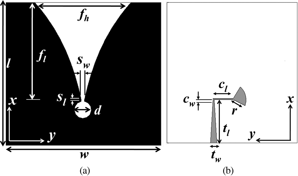
Fig. 1. Proposed Vivaldi antenna (a) front side (b) back side (black is FTO, gray is silver and white is soda-lime glass).
Table 1. Optimized dimensions of the Vivaldi antenna (units in mm).

Fabrication of antenna
The FTO coated soda-lime glass substrate with ohmic sheet resistance 8 Ω/sq is used for the fabrication of the antenna. The substrate is cut using a glass cutter according to the dimensions of the designed antenna. A mask is prepared according to the pattern of the antenna as shown in Fig. 1(a) and placed on the substrate. The unmasked FTO coated areas are removed using zinc powder and hydrochloric acid (HCl). After removing the unwanted portion of the FTO, it is washed thoroughly and sonicated with ethanol to remove any unnecessary by-products formed due to the chemical reaction between zinc powder and the HCl. The radial stub as shown in Fig. 1(b) is coated with silver on the back side of the substrate. Later coaxial connector is connected to the radial stub feed using silver conductive epoxy. The fabricated prototype is shown in Fig. 2.
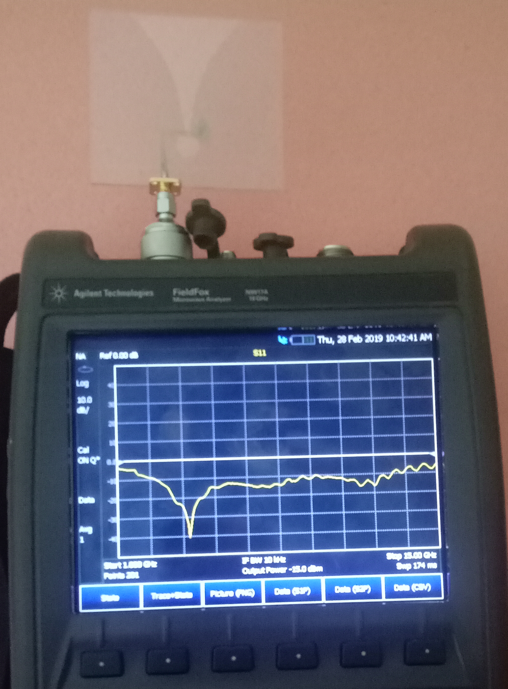
Fig. 2. Fabricated prototype of the transparent Vivaldi antenna.
Electrical properties of the antenna
The electrical properties of the antenna are analyzed to study the performance of the antenna. The electrical properties of the antenna are impedance characteristics and radiation pattern characteristics. The impedance characteristics of the fabricated antenna are tested using Keysight Field fox N9917A Microwave Analyzer. The simulated and the measured reflection coefficients of the transparent antenna are shown in Fig. 3. The slight mismatch between the measured and simulated results are attributed to the uneven distribution of the sheet resistance on the fabricated prototype. The antenna is fabricated using FTO coated glass substrate. The sheet resistance is unevenly distributed along the surface of the substrate, whereas in simulation, the FTO is characterized with a uniform sheet resistance of 8 Ω/sq. So, there is a slight mismatch between the simulated and measured results. However, the simulated and the measured reflection coefficients share common operating bandwidth extending from 2 to 6 GHz. The measured antenna operates over a frequency range of 2–6 GHz with a bandwidth of 4 GHz covering Wi-Fi, Bluetooth and 5 G applications.
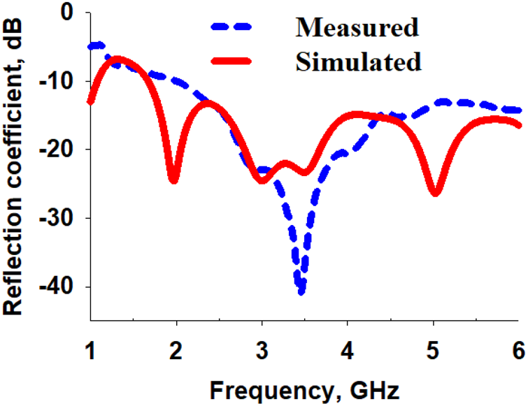
Fig. 3. Simulated and measured reflection coefficients of the proposed antenna.
The radiation pattern of the transparent Vivaldi antenna is measured in an anechoic chamber at a far-field distance in both planes (XZ and YZ). It has a directional radiation pattern with measured and simulated peak realized gain of 2.5 and 3.2 dBi at 4 GHz. The simulated and measured radiation pattern of the proposed antenna is shown in Fig. 4. The simulated radiation efficiency of the proposed antenna is greater than 28% over the entire frequency range. The simulated and measured gain and the simulated radiation efficiency of the proposed antenna are shown in Fig. 5. The measured realized gain is greater than −1 dBi over the entire frequency range.
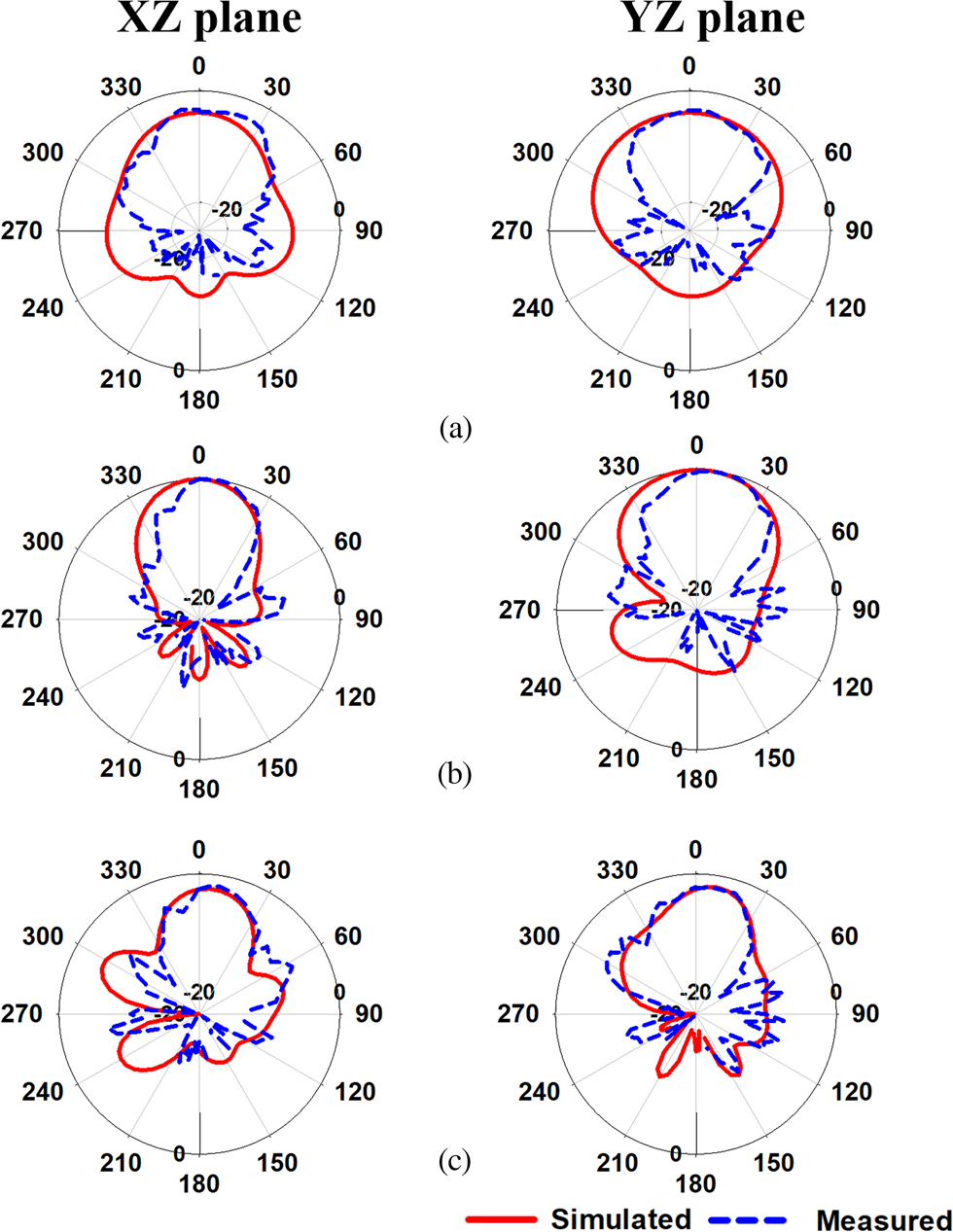
Fig. 4. Simulated and measured radiation pattern of the proposed antenna (a) 2 GHz, (b) 4 GHz and (c) 6 GHz.

Fig. 5. Simulated and measured gain & simulated radiation efficiency of the proposed antenna.
Energy harvesting mechanism for optically transparent antenna
The proposed antenna with radial stub feeding is integrated with a voltage multiplier circuit to harvest RF energy from the ambient environment as shown in Fig. 6. The voltage multiplier is an electrical circuit that converts AC power to dc voltage. It consists of capacitors and diodes. The diodes used in this circuit are OA70 germanium diodes with a maximum reverse voltage of 15 V and a maximum forward current of 50 mA. This diode is used for low resistance rectifier applications. The capacitors (C1, C2) and (C3, C4) used in the circuit are ceramic and electrolytic capacitors respectively. The ceramic capacitors are used for high-frequency applications while the electrolytic capacitors are preferred at lower frequencies. The input of the rectifier receives high-frequency signals, so ceramic capacitors, C1 = C2 = 0.22 μF are used. The output of the rectifier has low-frequency signals, hence electrolytic capacitors, C3 = C4 = 100 μF are used.
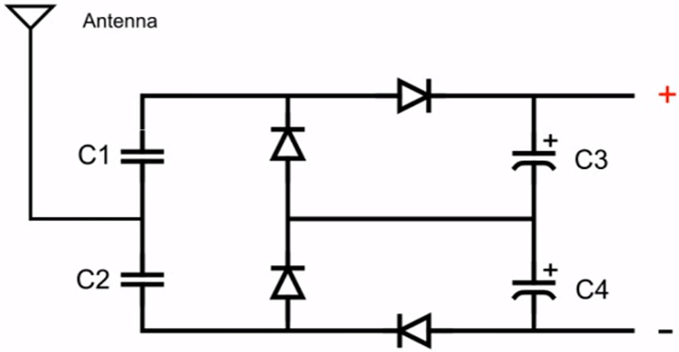
Fig. 6. Energy harvesting circuit.
The directional transparent UWB antenna collects ambient RF energy and transmits it to succeeding circuitry. The voltage multiplier converts the RF energy into a dc voltage. This circuit provides dc output voltage twice the peak of the input voltage as it operates as a doubler. The circuit is fabricated on a PCB board. The fabricated prototype of the RF energy harvesting circuit is shown in Fig. 7.

Fig. 7. Fabricated prototype of the RF energy harvesting circuit.
The antenna is connected to the circuit board on one end and the other end is connected to the multimeter as shown in Fig. 8. This setup is placed in an indoor laboratory where WiFi is available. The rectenna collected the RF energy from the environment and provided a dc voltage of 140 mV (Table 2).
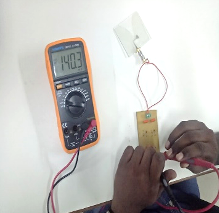
Fig. 8. Measurement setup of RF energy harvesting circuit.
Table 2. Comparison of the transparent antenna for RF energy harvesting in the literature.

The novelty of this paper is an exploration of transparent material as an RF energy harvester. The salient features of the antenna are:
1. The Vivaldi antenna is optically transparent with an optical transmittance of greater than 70%.
2. The peak gain of the antenna is 2.5 dBi.
3. The antenna operates from 2 to 6 GHz with a bandwidth of 4 GHz.
4. The antenna provides an output dc voltage of 140 mV.
Conclusion
The optically transparent rectenna has been designed, fabricated and tested using a soda-lime glass substrate coated with FTO. This proposed antenna operates at a frequency of 2–6 GHz with a directional radiation pattern. It has simulated radiation efficiency greater than 28% over the entire operating frequency range. It has a peak realized gain of 2.5 dBi at 4 GHz. It has an optical transmittance greater than 70% in the entire visible region. A voltage multiplier is integrated with the proposed antenna to obtain a DC voltage of 140 mV.
 Potti Devisowjanya obtained her B.Tech. degree in electronics and communication engineering from Raghu engineering college, Visakhapatnam and M. Tech. degree in Andhra University, Visakhapatnam. She received her Ph.D. from Anna University for her research work on optically transparent antennas. She is currently working as an assistant professor at Amrita School of Engineering. Her research work includes automotive antennas, RF energy harvesting and vehicular cognitive networks.
 Dr. Mohammed Gulam Nabi Alsath, obtained his B.E. and M.E. degrees from Anna University, Chennai with university 3rd rank in UG and gold medal in PG. He received his Ph.D. degree from Anna University for his research work on automotive antennas. He currently serves as an associate professor in the Department of ECE, SSN. Prior to joining SSN, he was with Dhaanish Ahmed College of Engineering, Chennai for 2 years. His research interests include microwave components and circuits, antenna engineering, signal integrity analysis and solutions to EMI problems. To his credit, he has filed 16 Indian patents and published several research articles on antennas and microwave components in leading international journals. He has also presented and published his research papers in the proceedings of international and national conferences. He is currently serving as associate editor in IET Microwaves Antennas and Propagation.
 Dr. Savarimuthu Kirubaveni, obtained her B.E. and M.E. degrees from Anna University, Chennai with University rank in both UG and PG. She currently serves as an associate professor in the Department of ECE, SSN. She has 7 years of teaching and research experience. Her research interests include MEMS and NEMS device design and VLSI design. She is currently involved in the growth of ZnO nanorods for piezoelectric energy harvester and gas sensor applications. She has over twenty-five research publications in national/international conferences and twelve international journals. She has completed a project titled “MEMS based piezoelectric energy harvester” funded by SSN Trust. She is currently involved in the project titled “ZnO based VOC sensor” as a principal investigator funded by SSN Trust. She is an active life member in IETE. She has guided over 25 projects for under graduate and post graduate students.
 G Sudhilaya, received a bachelor degree in electronics and communication engineering from Kingston Engineering College (2013–2017), Vellore, India. Master's in VLSI design from Sri Siva Subramaniya Nadar College of Engineering (2017–2019), Chennai, India. Currently working as a research scientist in SAMEER-Centre for Electromagnetics, Chennai, India. Research works based on circularly polarized antenna for defense application, 5G phased array antenna, RF integrated layout for 5G-mmwave application.


