I. INTRODUCTION
Meta-materials have been introduced for various microwave devices and components. Increasing attention has been paid on by electromagnetic waves community in employing them for novel functionalities and size reduction that cannot be achieved using conventional materials. Left-handed meta-materials (LHMs) are one of these meta-materials which are characterized by simultaneous negative permittivity and permeability. Realization of LHMs has been proposed using a transmission line (TL) periodically loaded with series capacitors and shunt inductors, named as composite right-/left-handed (CRLH) TL [Reference Caloz and TItoh1, Reference Eleftheriades and Balmain2]. Hence, novel CRLH microwave components [Reference Eleftheriades3–Reference Dong and Itoh5] and antennas [Reference Lee, Huang, Gummalla and Achour6–Reference Dong and Itoh8] have been reported.
Since the early years in this century, there has been an increase demand for multiband, omni-directional antennas to meet numerous increase in the wireless communication services that operate at different frequency spectrums. Low-cost printed monopole-based multiband antennas have been employed [Reference Wong9]. A printed monopole antenna can be designed in different geometrical shapes using microstrip and CPW feeding configurations. There is a challenge in introducing more and designing arbitrary frequency bands with compact size and simple realization. The multiband techniques can be done by using meandering line [Reference Park, Kang and Sung10] or using different radiators on top and bottom sides of the monopole [Reference Liu, Wu and Dai11, Reference Chang and Kiang12]. However, this may increase the antenna design and fabrication complexity. It has also been suggested using different interconnected radiating resonators/slots on the patch [Reference Moosazadeh and Kharkovsky13] with different shapes. However, these resonators are required to be half wave length which may increase the overall antenna dimensions. Consequently, different proposals for quad band antennas are presented over the last few years [Reference Ding and Wang14–Reference Ren, Hu and Jiang21].
Multiband antennas can also be realized based on metamaterial TL as resonant antennas. Several successful approaches have been suggested [Reference Dong and Itoh22–Reference Abdalla and Fouad28]. Although most of these antennas have achieved multiband functionalities, they have small gain. In order to have higher gain, metamaterial structures have been employed to load different conventional resonant antennas such as monopole/dipole antennas which have also provided arbitrary operating band [Reference Zhu and Eleftheriades29–Reference Abdalla, Abo El-Dahab and Ghouz31]. Among these antennas, quad band proposals have been also reported [Reference Elsheakh and Safwat32, Reference Nandi and Mohan33].
The ideal simple half mode CRLH cell (H-CRLH) was suggested in [Reference Abdalla and Hu34, Reference Abdalla, Fouad, Ahmed and Hu35] by either using the shunt or series loading elements in complete CRLH cell to design a dual/triple band antennas, respectively. These antennas were monopole loaded by meandered lines. However, their radiation mechanism can be explained as inspired from open circuit terminated H-CRLH cell. In this way, dual/triple band design method was designed independently. Consequently, a complementary cell of the H-CRLH was loading a monopole; this idea was discussed in [Reference Abdalla, Abdelnaby and Mitkees36, Reference Abdalla, Hu and Muvianto37] to design a triple band antenna. However, by increasing the independent desired design bands, the concept of H-CRLH design method was limited.
Therefore, in this paper, we introduce a simple new analysis and design and implementation of quad band antenna based on loading a monopole patch by three different and independent resonators inspired from the shunt branch of CRLH unit cells. The antenna is CPW fed and it serves the bands centered at 2.6, 3.35, 5.15, and 6.1 GHz with good gain and omni-directional pattern.
II. ANTENNA STRUCTURE AND DESIGN PRINCIPLES
The novelty of the proposed technique in this paper is its ability to introduce many bands by loading a monopole patch antenna as shown in Fig. 1(a). As shown in the figure, three different resonators are added to the monopole patch at three different positions. As a consequence, three different resonances were generated in addition to the original monopole resonance. Hence, quad band antenna can be achieved. In this way, a compact and multiband antenna design methodology is possible. The initial layout design of the quad band antenna is shown in Fig. 1(b). The antenna is designed on low-cost FR4 substrate with ε r = 4.4, and 1.6 mm thickness. As it can be seen, the three resonators consist of a slot inductor in parallel with an eight fingers interdigital capacitor. All the fingers widths and spacing are of 0.2 mm. The detailed dimensions for the antenna are tabulated in Table 1.
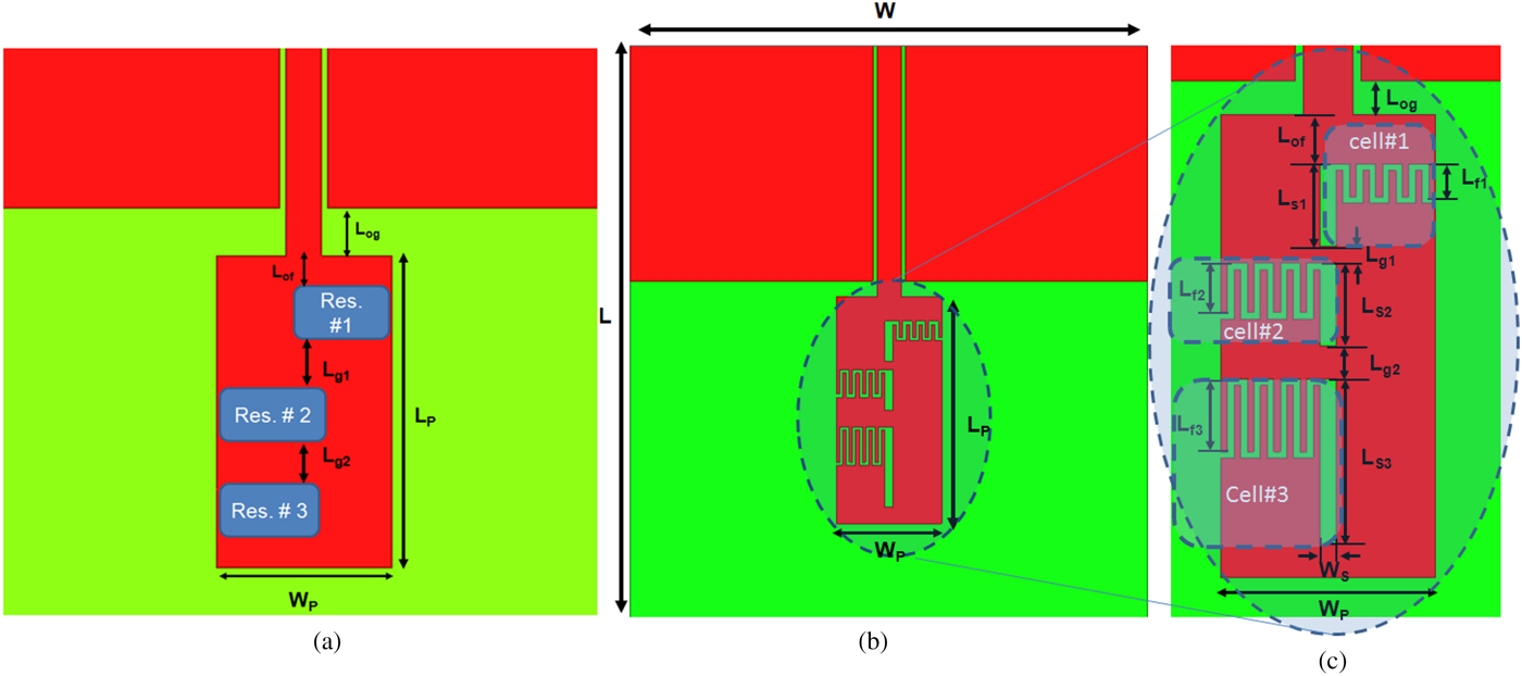
Fig. 1. The proposed quad band loaded monopole antenna. (a) The suggesting loading schematic, (b) the antenna geometry, (c) the detailed loaded patch.
Table 1. The detailed dimensions for the quad band antenna in Fig. 2.

All design parameters are in mm.
The dimensions were selected so that the patch length is approximately quarter wavelength at first band (2.6 GHz) and the patch width was adjusted for efficient radiation and good matching. The inductor and capacitor of the three resonators were adjusted at the three other frequencies (3.35 GHz), (5.15 GHz), and (6.1 GHz), individually.
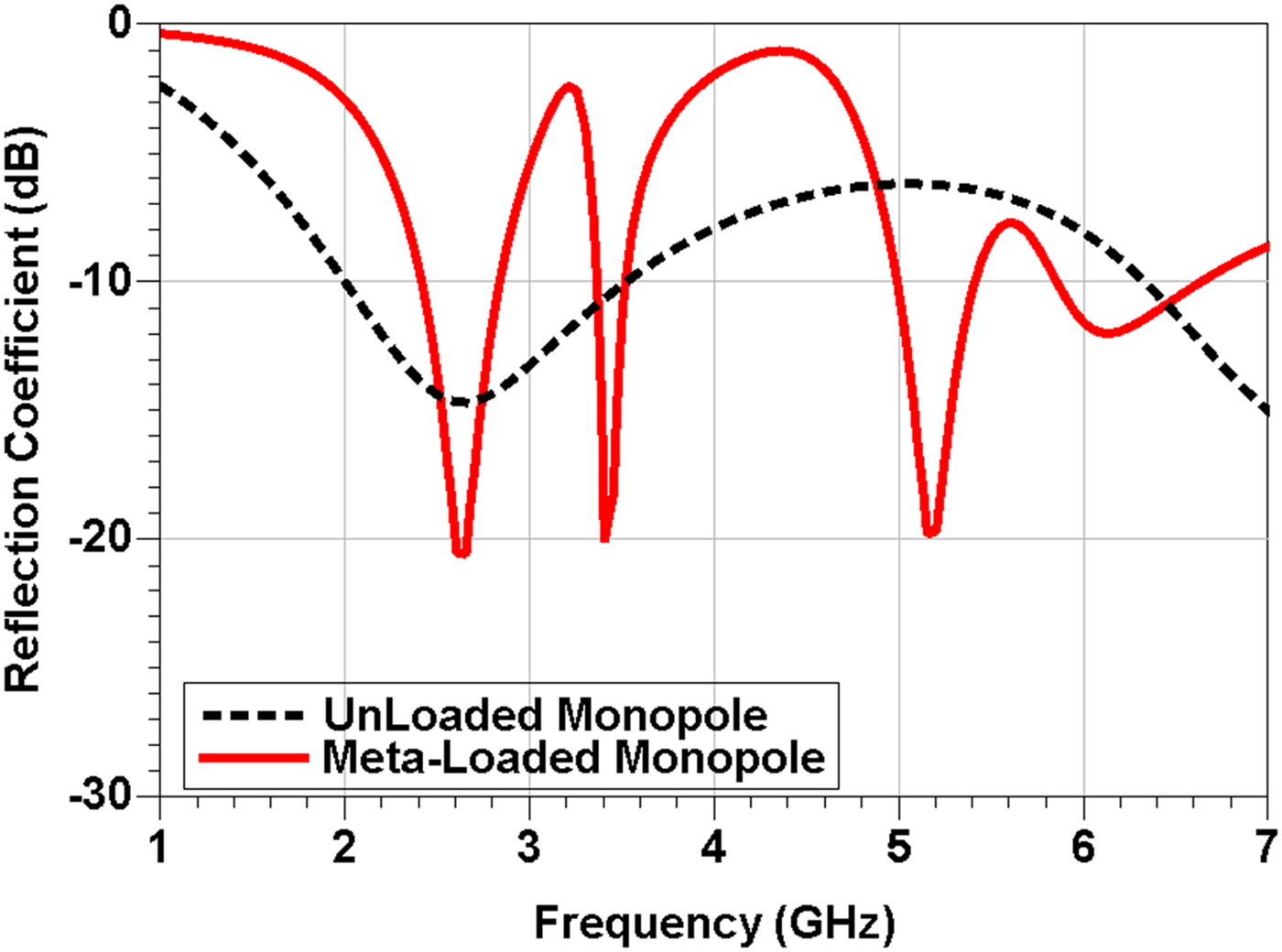
The simulated reflection coefficient for a non-loaded monopole and loaded monopole antennas are shown in Fig. 2. It is clear that the non-loaded monopole antenna can resonate only at 2.6 GHz at which the reflection coefficient is −15 dB and it has a wide −10 dB bandwidth that extends from 2 to 3.5 GHz. On the other hand, the loaded monopole antenna can demonstrate quad bands. The first band is the same as the unloaded one at 2.6 GHz. The three other resonances are at 3.35, 5.15, and 6.1 GHz with <−10 dB center reflection coefficient.

Fig. 2. The simulated reflection coefficient of the unloaded and loaded monopole antennas.
III. THE OPERATING PRINCIPLES OF THE QUAD BAND ANTENNA
To confirm the independent frequency bands of the quad band antenna, the antenna has been simulated for different patch length (L p) as shown in Fig. 3, capacitor finger length (L f3) as shown in Fig. 4, capacitor finger length (L f2) as shown in Fig. 5, and capacitor finger length (L f1) as shown in Fig. 6. In Fig. 3, it is obvious that by changing L p, only the first band is shifted from f 1 = 2.6 GHz to 2.7 GHz and 2.8 GHz corresponding to L p = 16, 15, and 14 mm, respectively. It can also be noticed that the other three resonance frequencies are almost constant at f 2 = 3.4 GHz, f 3 = 5.2 GHz, and f 4 = 6.25 GHz. In Fig. 4, by changing L f3, only the second band changes from f 2 = 3.3 GHz to 3.4 GHz and 3.5 GHz corresponding to L f3 = 2.4, 2.2, and 2 mm, respectively. The three other bands are not changed f 1 = 2.65 GHz, f 3 = 5.15 GHz, and f 4 = 6.15 GHz. In Fig. 5, f 3 is changed from 5 to 5.2 and 5.35 GHz by changing L f2 from 1.7 to 1.5 and 1.3 mm, respectively. Little change for f 1 = 2.65 GHz, f 2 = 2.65 GHz, and f 4 = 6.15 GHz can be observed.

Fig. 3. The simulated reflection coefficient of the loaded monopole antenna for different L p values.
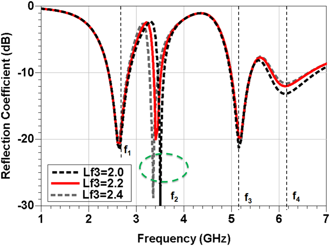
Fig. 4. The simulated reflection coefficient of the loaded monopole antenna for different L f3 values.
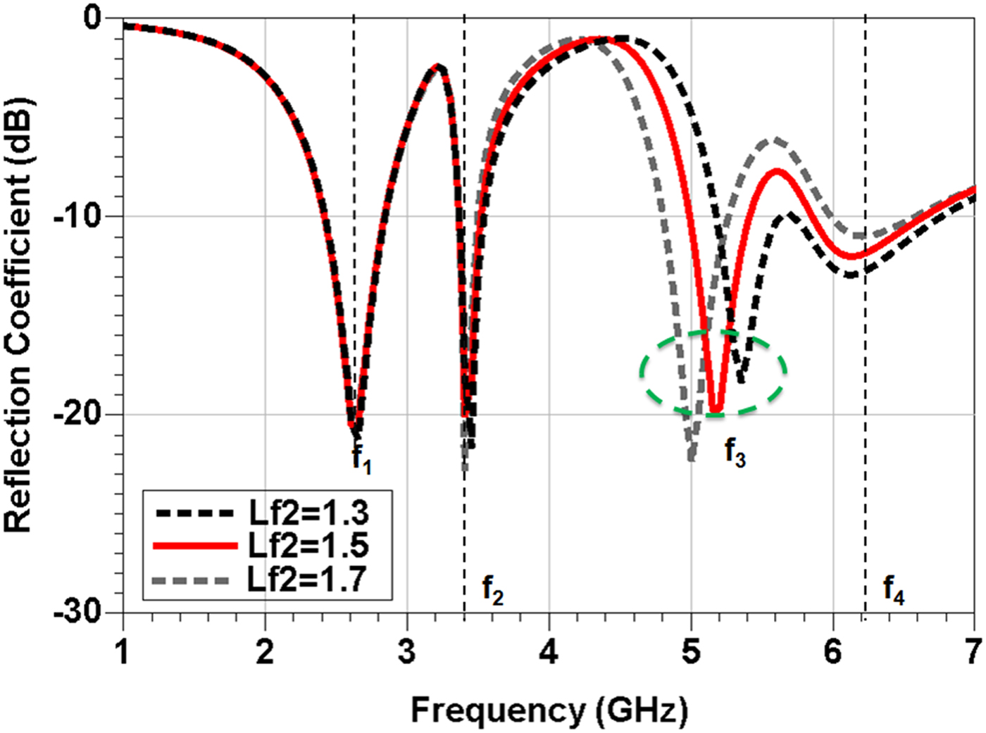
Fig. 5. The simulated reflection coefficient of the loaded monopole antenna for different L f2 values.
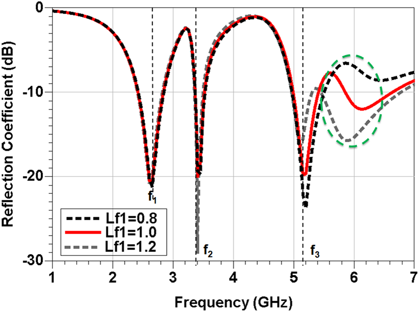
Fig. 6. The simulated reflection coefficient of the loaded monopole antenna for different L f1 values.
Finally, as it can be observed from Fig. 6, by changing L f1, only the fourth band is changing from f 4 = 5.9 to 6.15 and 6.4 GHz corresponding to L f1 = 1.2, 1, and 0.8 mm, respectively. The three other bands are not changed f 1 = 2.6 GHz, f 2 = 3.4 GHz, and f 3 = 5.2 GHz. The previous parametric analyses confirmed that the design of each resonance is controlled independently which make these frequency bands to be easily controlled. In other words, the first band is designed by the patch size, the second band by resonator #3, the third band by resonator #2, whereas the fourth band is designed by resonator #1.
From previous results, it is very clear that the proposed analysis technique is powerful in designing the antenna bands independently. The success of this analysis can be further for higher antenna bands in small size which can be considered a good and simple contribution over multiband antennas which may be extended to more than quad band antennas.
IV. QUAD BAND ANTENNA RESULTS AND DISCUSSION
Based on the previous parametric analysis for the loaded monopole antenna, an optimized antenna layout is shown in Fig. 7. It can be seen that the positions of the three interdigital capacitors have been moved along the cell. The objective was based on achieving best possible matching for all designed four bands. Moreover, to decrease the patch size while maintaining the same electrical length and hence the same resonant frequencies, the third slot has been shaped to have T shape at the end. This affects the operating frequencies of the first and second bands but not the third and fourth bands

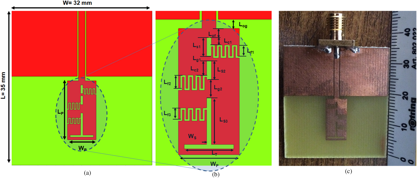
Fig. 7. The quad band metamaterial inspired antenna. (a) The 2D layout; (b) the detailed loaded monopole patch L p = 13.5 mm, W p = 6.5 mm, L T = 5.3 mm, L C1 = 0.8 mm, L C2 = 1.55 mm, L C3 = 1.1 mm; (c) the fabricated antenna prototype.
Finally, the simulated and measured reflection coefficient is shown in Fig. 8. The results confirm quad band operation addressed by reflection coefficient lower than −10 dB. The center frequency is at 2.6 GHz (−10 dB bandwidth from 2.5 to 2.7 GHz), 3.35 GHz (−10 dB bandwidth from 3.2 to 3.55 GHz), 5.15 GHz (−10 dB bandwidth from 4.95 to 5.35 GHz), and 6.1 GHz (−10 dB bandwidth from 5.65 to 7.2 GHz). The figure also demonstrates good agreement between the simulated and the measured results. However, there are some discrepancies at the fourth band. The quad band antenna size is compared individually to single-band microstrip patch antenna.
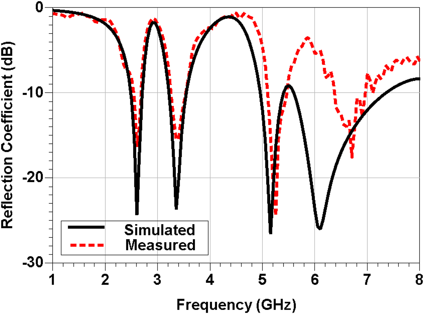
Fig. 8. The simulated and measured reflection coefficients of the quad band loaded monopole antenna.
A conventional microstrip patch size is 35.1 mm × 27.1 mm at 2.6 GHz, with overall antenna size = 84 mm × 62 mm, 27 mm × 21 mm, with overall antenna size = 65 mm × 50 mm, at 3.35 GHz, 18 mm × 13 mm at 5.15 GHz, with overall antenna size = 36 mm × 42 mm and finally 11 mm × 11 mm at 6.1 GHz, with overall antenna size = 32 mm × 35 mm. On the other hand, the quad band antenna has a radiator size (13.5 mm × 6.5 mm) with overall size (35 mm × 32 mm), whereas the feeding length (20 mm) is the same in the two cases. Thus, the proposed radiator is only 9, 15, 37.5, and 72.5%, whereas the whole designed antenna size is 21, 34.5, 70, and 100% at the former frequencies, respectively.
Further confirmation of the resonance mechanism of the loaded monopole antenna can be done by plotting the surface current distribution at the four resonant frequencies. These plots are depicted in Figs. 9(a)–9(d). As we can observe, at 2.6 GHz in Fig. 9(a), the current is concentrated at the three resonators and the whole monopole. At 3.35 GHz, in Fig. 9(b), the monopole became to be inefficient in radiation and most of the current is concentrated at the three resonators with basically dominant one at resonator #3. This result agrees with previously explained one in Fig. 4. At Fig. 9(c) at 5.15 GHz, the second resonator became the dominant one in radiation which also agree with conclusion in Fig. 5. Finally, at 6.1 GHz in Fig. 9(d), the current is concentrated at the first resonator that agrees with results in Fig. 6.

Fig. 9. The simulated current density distribution over the monopole radiator at (a) 2.6 GHz, (b) 3.35 GHz, (c) 5.15 GHz, and (d) 6.1 GHz.
The antenna radiation properties at the four operating bands have also been investigated by examining the 3D radiation gain patterns at the center frequencies as plotted in Fig. 10. At 2.6 GHz, the figure is clearly showing a typical omni-directional pattern (doughnut-like). The simulated gain is about 0 dB. At 3.35 GHz, we can notice that the antenna preserves the typical omni-directional radiation pattern with gain = 1.6 dB. Similar observation is obvious at 5.15 GHz with 1.2 dB gain. Finally, at 6.1 GHz, the pattern has more directive properties with higher gain = 2.7 dB. However, the same directions of maxima and nulls do not change.

Fig. 10. The simulated 3D radiation pattern gain at 2.6, 3.35, 5.15, and 6.1 GHz.
Finally, as a key parameter of the antenna, the simulated radiation efficiency of the antenna at the four former frequencies (2.6, 3.35, 5.15, and 6.1 GHz) were extracted to be 87, 86.5, 71.2, and 85%, respectively. This can be commented as the proposed antenna is almost constant which is a typical property of the antenna.
To evaluate the proposed antenna performance, a comparison between this work and other microstrip- and CPW-fed multiband monopole/other antennas for similar applications is summarized in Table 2. The comparison demonstrates the proposed antenna-independent design bands capability in addition to its competitive properties and size.
Table 2. A comparison between recent published quad band antennas and the proposed antenna in this paper.
V. CONCLUSION
A simple technique for designing quad band omni-directional antenna with independently controllable frequency bands has been proposed with experimental demonstration. The technique is based on loading a monopole patch with three uncoupled resonators. The fabricated antenna can operate at 2.6, 3.35, 5.15, and 6.1 GHz. The analysis confirmed that the four bands can be controlled independently. The fabricated antenna has a size of 35 mm × 32 mm which is only 9% size of conventional single-band microstrip antenna at the lowest frequency band. The antenna radiation patterns validate the design showing that good antenna gains have been achieved at all four bands. The proposed technique can be adapted for multi-band operation.
 Mahmoud A. Abdalla was born in 1973, received the B.Sc. degree, with grade of excellent with honors, in Electrical Engineering from the Electronic Engineering Department, Military Technical College, Cairo, Egypt in 1995. He was awarded the M.Sc. degree in Electrical Engineering from Military Technical College in 2000, and the Ph.D. degree from Microwave and Communication Group, School of Electrical Engineering, Manchester University, UK, in 2009. He has been with Military Technical College since 1996 where he is now an associate professor in Electronic Engineering Department. His research has focused on different metamaterial applications in microwave and millimeter bands specially microwave components, miniaturized multiband antennas, and ferrite components. His research also includes electromagnetic energy harvesting systems, EBG components, adaptive antenna systems for DOA estimation and interference cancellations, and radar absorber designs. He has published more than 130 peer-reviewed journal and conference papers. Dr. Mahmoud Abdalla is a senior member of the IEEE and the European Microwave Association EuMA. He is currently a reviewer in many electromagnetic journals such as IEEE Antennas and Wireless Propagation Letters; IEEE Transaction in Magnetics; IET Microwave, Antenna and Propagation; International Journal of Microwave and Wireless Technologies; Journal of Electromagnetic Waves (JEMW); Progress in Electromagnetic Research; European Physical Journal – Applied Physics; Journal of Applied Computational Electromagnetic Society; Advanced Electromagnetic and some others.
 Zhirun Hu (M'98) received his BEng in Communication Engineering from Nanjing, China, in 1982, Master in Business Administration, and Ph.D. in Electrical and Electronic Engineering from the Queen's University of Belfast, United Kingdom, in 1988 and 1991. In 1991, he joined the Department of Electrical and Electronic Engineering, University College of Swansea, as a senior research assistant in computational semiconductor device simulation. In 1994, he was with the Department of Electrical and Electronic Engineering, the Queen's University of Belfast, as a research fellow in silicon MMIC design, realization, and characterization. In 1996, he joined GEC Marconi, as a microwave technologist working on microwave/millimeter-wave device and circuit design and characterization. He was a lecturer with the Department of Electronic Engineering, King's College London from 1998 to 2003. He is now with the School of Electrical and Electronic Engineering, the University of Manchester. He has published more than 200 peer-reviewed journal and conference papers.