Introduction
Metamaterials are actually the special type of engineered materials that are usually not available in nature. They need to embed periodic unit cell for their formation to create naturally unavailable electromagnetic properties. Moreover, these materials have the power to control the electromagnetic wave beams to show their unorthodox characteristics. These unusual features of the metamaterials totally depend on the geometry of the atomic construction. It has been started from the year 1968, Veselago [Reference Veselago1] observed unique properties of materials having negative permittivity (ε) and permeability (μ). However, it was not appreciated until 2000 when Smith et al. [Reference Smith, Padilla, Vier, Nemat-Nasser and Schultz2] validated a new unreal with these unconventional properties (both permittivity and permeability were negative) is called left-handed metamaterial. In case of negativity, it has been categorized as single-negative (either permittivity is negative or permeability is negative) and double-negative (both permittivity and permeability are negative). There is also a term called near-zero refractive index metamaterial (NZRI) where permittivity and permeability of a material become nearly zero on a particular range of frequency. Having these captivating electromagnetic phenomena, necessary applications, such as SAR reduction [Reference Sultan, Abdullah, Abdallah and Hashish3, Reference Faruque, Islam and Misran4], superlenses, antenna design [Reference Islam, Islam, Samsuzzaman and Faruque5–Reference Yang, Singh and Zhang7], filters [Reference Fang, Gao and Liu8–Reference Singh, Al-Naib, Cao, Rockstuhl, Koch and Zhang10], invisibility cloaking [Reference Islam, Faruque and Islam11, Reference Landy and Smith12], electromagnetic absorber, and electromagnetic band gaps can be employed by metamaterials. In some cases, intrinsic negative permittivity is found; yet, it is rare to find negative permeability with a natural medium. Even artificial structures can hardly obtain the negative permeability. Concurrently, it is really difficult to get the negative refractive indices. Currently, multi-band metamaterial absorbers have become an auspicious application in the detection of explosives, even in bolometers, and thermal detectors [Reference Shen, Cui, Zhao, Ma, Jiang and Li13]. Moreover, a very few studies have been made in designing this type of materials [Reference Gong and Zhao14–Reference Huang, Wen, Yang and Xie16]. Different alphabetic shapes have become popular for particular operations; for example, Benosman and Hacene [Reference Benosman and Hacene17] introduced a double S-shaped metamaterial that showed negative values of refractive index (η) from 15.67 to 17.43 GHz. Mallik et al. [Reference Mallik, Kundu and Goni18] proposed various U-shaped rectangular array structures left-handed aspect at approximately 5, 6, and 11 GHz. A V-shaped metamaterial was presented by Ekmekci and Turhan-Sayan [Reference Ekmekci and Turhan-Sayan19], dual-band tunable negative refractive index metamaterial with F-shape structure was presented by Rizwan et al. [Reference Rizwan, Jin, Rehman, Hou, Li, Butt and Ali20], the architecture showed double-negative characteristic. Zhou and Yang et al. [Reference Zhou and Yang21] designed an S-shaped 15 × 15 mm2 chiral metamaterial for X- and Ku-band applications. Though the effective medium ratio (EMR) was not higher than 4. For the purpose of the application on C, X, and Ku bands, Alam et al. [Reference Alam, Faruque and Islam22] design split P-shaped double negative (DNG) for different unit cells and array sizes.
A metamaterial unit cell of combined modified H-shaped has been proposed in this paper. The structure covers multiple bands (L, C, X, and Ku) of frequencies for the transmission coefficient. For effective parameters, it covers the X and Ku bands with double-negative characteristic which is suitable for satellite communication.
Methodology
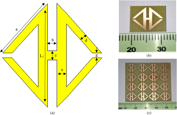
The diagram of the prospective modified H-shaped unit-cell composition is itemized in Fig. 1. The two split ring resonators (SRR) are connected with the substantial H-shaped structure. Each unit cell comprises with 12 mm in length and 12 mm in width. All elements have the thickness of 0.35 mm. Each H-shaped split resonator has the width of 1 mm with a same split gap. The outer length of the resonator is 11 mm where the split of each of the resonators is 0.5 mm. The entire patch (made of copper) is developed on a substrate called FR-4 with a dielectric constant of ε r = 4.3, a dielectric loss-tangent of tan δε = 0.025. Sides of the substrate are a = b = 10 mm and the thickness is t = 1.6 mm. Designed parameters of the proposed metamaterial are enlisted in Table 1.

Fig. 1. Metamaterial unit cell: (a) Proposed geometry; (b) fabricated geometry; (c) prototype array.
Table 1. Parameters of the unit cell
A prototype array and a unit cell are fabricated for the purpose of measurement. The area of the array is 45 × 45 mm2. Two waveguide ports are used to propagate the electromagnetic waves to excite the configuration in two opposite directions of the Z-axis. Perfect electric conductor (PEC) and perfect magnetic conductor (PMC) were used along the vertical direction of the x- and y-axes, respectively; and for the free-space simulation purposes, a frequency domain solver was utilized. Moreover, for the analysis purpose of these configurations, a tetrahedral mesh was used with a flexible mesh. The normalized impedance was 50 Ω and the system was performed from 1 to 18 GHz.
The area of the prototype is 12 × 12 mm2, which is fabricated for the purpose of measurements. By settling the perspective unit cell in between, the waveguides as per Fig. 2 to determine the scattering parameters accurately of the combined P-shaped split metamaterial. To determine the parameters, we have used a vector analyzer Agilent N5227A. To calibrate perfectly, an Agilent N4694-60001 is utilized.
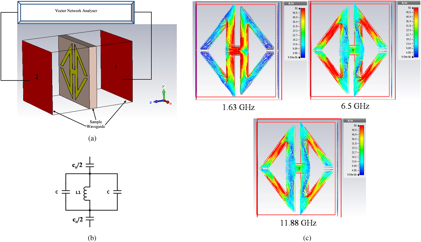
Fig. 2. (a) Experimental setup for measuring S parameter; (b) equivalent circuit of the unit cell; (c) current distribution on the unit cell at various frequencies.
Equivalent circuit model
The equation for this type of passive LC circuits of metamaterial structure is
 $$f = {\rm \;} \displaystyle{1 \over {2\pi \sqrt {LC_{\rm 0}}}},$$
where L represents cumulative inductance and C represents cumulative capacitance. Here C 0 represents the capacitance required that forms in two adjacent unit cells. Here, metal loops create inductance and splits create capacitance. When the electromagnetic waves applied through the structure, two types of coupling occurred. Electric resonances are produced due to the formation of coupling between gaps and electric field. Magnetic resonances are formed because of loops and magnetic field. Commonly, the total capacitance formed between the gaps is:
 $$C = {\rm \;} \varepsilon _0\varepsilon _r\displaystyle{A \over d}\left( F \right),$$
where ε 0 is the free space permittivity and ε r is the relative permittivity, respectively; A infers the cross-sectional area of the gap and d refers to the gap length. Hence, the total inductance can be estimated from [Reference Alu, Bilotti and Vegni23] as
 $$L_1 = \mu _0\left\{ {\displaystyle{{2c} \over {2w + h}} + \displaystyle{{\sqrt {{\left( {2w + h} \right)}^2 + l^2}} \over c}} \right\}t.$$
Therefore, the equivalent capacitance will be apparent as
 $$C_o \approx \varepsilon _0\displaystyle{{\left( {2w + h} \right)} \over \pi} \ln \left( {\displaystyle{{2c} \over {a - l}}} \right),$$
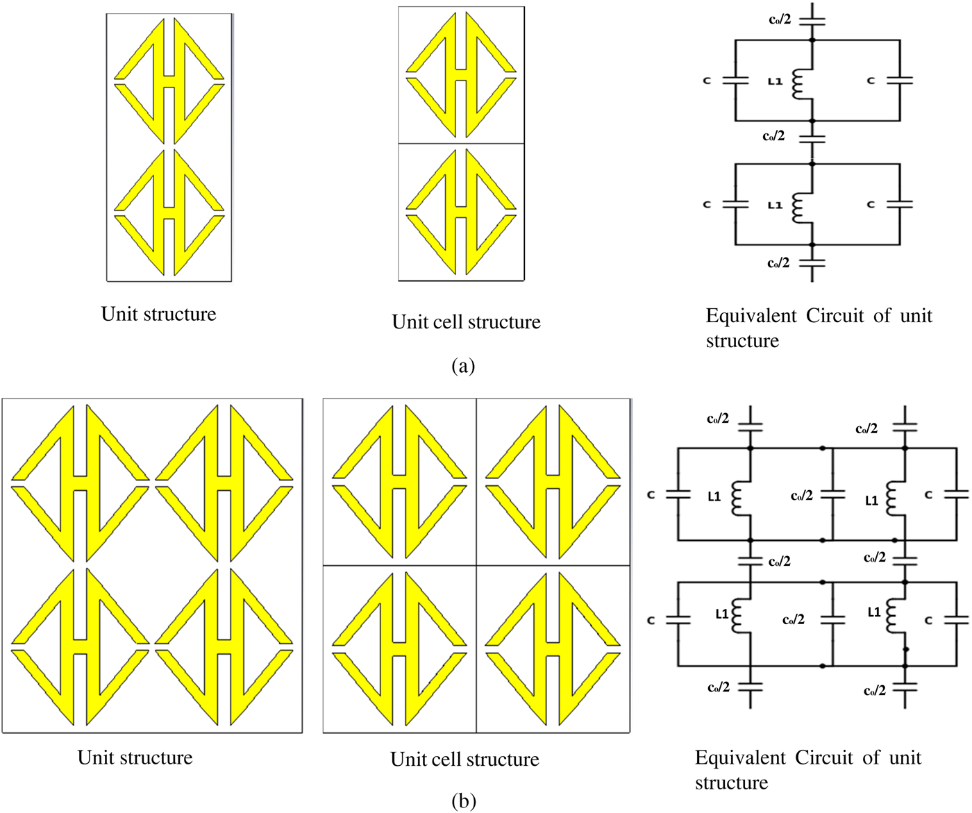
where μ 0 is 4π × 10−7 H/m, ε 0 is 8.854 × 10⁻¹² F/m, width w, height h and length l. The resonances of the proposed structure are formed because of several series and parallel inductances and capacitances. Splits maintained the capacitive effect and metal fillets are pledged to effect of inductance. The capacitive effects are symbolized in the equivalent circuit as C and the inductive effects are as L. The equivalent circuit of the proposed metamaterial is shown in Figs 2(b) and 3 shows different array structures and their corresponding equivalent circuits.

Fig. 3. Structure and equivalent circuit of (a) 1 × 2 array; (b) 2 × 2 array.
Results and discussions
There are plenty of ways to find out the effective parameters of a unit cell such as Nicolson–Ross–Weir (NRW) method, direct retrieval method of refractive index (DRI), etc. This paper highlights the electromagnetic properties using the real values of ε, μ, and η using S 11 and S 21.
Analysis of unit cell
As the unit cell is printed on an FR-4 substrate with an area of 144 mm2, it has been measured within a frequency range of 1–18 GHz. The simulation is done by CST microwave studio and the result is compared with the measured one after the fabrication to measure the transmission coefficient (S 21). The measured result follows the similar pattern as there is a bit shitting of frequencies in the C-band. The transmission coefficient exhibits a wide band with a coverage of L, C, X, and Ku bands. The first resonance is found in the L-band at frequency 1.63 GHz. Then a wide band from 4.68 to 17.18 GHz with a little band gap of 500 MHz. The shifting is occurring due to fabrication error and the free space measurement process.
The optimized resonance frequency is 8.9 GHz. Figure 4(a) shows the magnitude of the transmission coefficient (S 21) and Fig. 2(c) shows the current distribution of the unit cell at 1.63, 6.50, and 11.88 GHz. In the proposed formation, inductances are formed by the metal strip and the capacitances are formed by the splits. A homogeneous wave with polarization is an incident in the y-axis and propagation in the x-axis to the structure. Additionally, dimensional scattering consequence, the electric field in the x-direction induces a magnetic dipole in the y-direction, and the magnetic field in the y-direction induces an electric dipole in the x-direction [Reference Hasar, Barroso, Sabah, Kaya and Ertugrul24]. Due to the antithetical geometry of the structure, a reverse current flow is noticed in the metal fillet of the configuration. Moreover, magnetic resonances are formed by the coupling between the magnetic fields and loops [Reference Hasan, Faruque, Islam and Islam25].
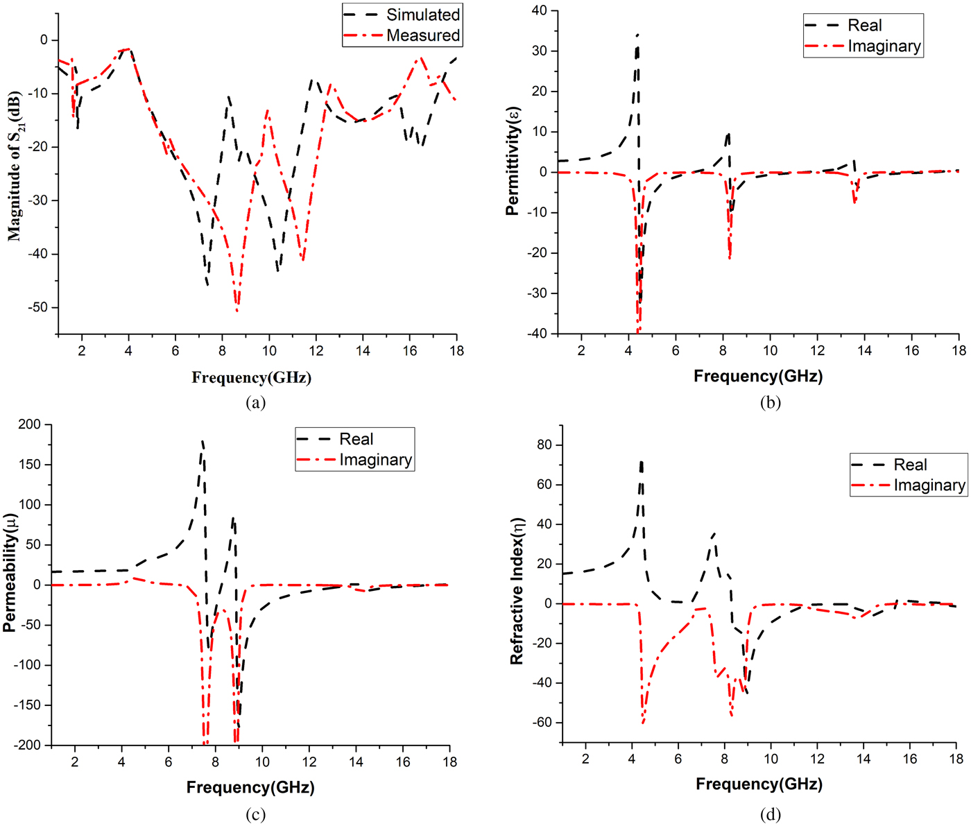
Fig. 4. (a) Measured and simulated results of S 21; real and imaginary values of (b) effective permittivity (ε) versus frequency; (c) effective permeability (μ) versus frequency; (d) refractive index (η) versus frequency.
By using S 21 and S 11 parameters, the effective parameters, i.e., effective permeability and effective permittivity can be obtained [Reference Luukkonen, Maslovski and Tretyakov26]. Figures 4(b) and 4(c) show the result of effective permittivity and effective permeability, respectively.
Figure 4(b) shows negative permittivity at resonating points. It shows negativity at 4.45–6.73, 8.3–11.4, and 13.59–16.86 GHz. Figure 4(c) shows the negative permeability at 7.61–8.25, 8.88–13.67, and 14.12–17.32 GHz. At lower frequencies, the current flow matches with the applied field. But in case of higher frequencies, it is not possible for the current to cope up with the applied field when the permeability becomes negative. In the gap, there is a change in the current produced of an SRR is regulated to a fluctuating magnetic field. At low frequency, the current remains in phase with the applied field, but it fails to remain in phase at higher frequencies and as a result, negative permeability is produced.
In Fig. 4(d), real and imaginary parts of η are plotted as a function of frequency. The curve shows negativity at 8.31–15.43 and 17.43–18 GHz. Table 2 shows the frequency range of refractive indices with effective parameters of the unit cell at different resonating frequency bands. The refractive index shows negativity when the permittivity and permeability both become negative. Here η shows certain negativity at different bands of frequencies. Hence, the designed unit cell has significant portions, where all the three effective parameters becomes negative. Therefore, this unit cell can be claimed as double-negative metamaterial as it has negative peaks at 8.9 and 14.3 GHz in all the three effective parameters which is shown in Table 2 with bandwidths.
Table 2. Frequency range of effective parameters
Array analysis
Figure 3 describes the array formation and the equivalent circuit of the unit structure and unit-cell structure which are placed vertically on the basic unit structure on the same FR-4 substrate. The array structure is measured within the frequency range of 1–18 GHz. For unit structure, both the patches are placed 0.5 mm apart from each other on the substrate. On the other hand, in case of unit-cell structure, the gap between the patches is 1 mm and the similar approach was used to assess the attainment of the array.
Unit structure analysis
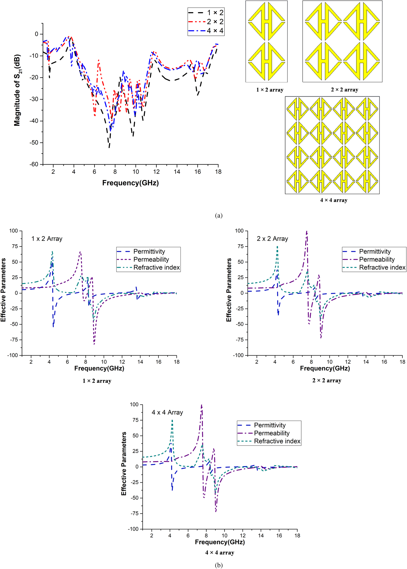
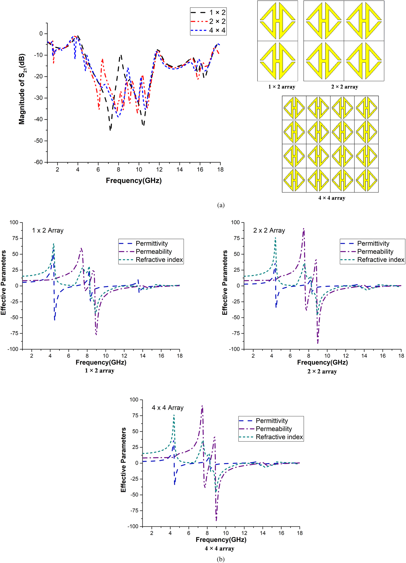
Figure 5(a) shows the transmission coefficient of the array structures. It is apparent that the resonances of the frequencies are found at the same points as the unit cell, but having greater negative magnitudes. The S 21 improves a bit as there is no band gap in between 4.68 and 17.18 GHz in case of 1 × 2 array. But it shows a little gap of about 100 MHz for 2 × 2 and 4 × 4 arrays. Figures 5(b) and 5(c) exhibit the real and imaginary values of the permittivity and permeability as a function of frequency of array structures.

Fig. 5. (a) S 21 versus frequency and array formations; (b) effective parameters versus frequency for the 1 × 2, 2 × 2, 4 × 4 array of the unit structure.
From Figs 5(b) and 5(c), it is observed that the negative values for the single unit-cell and the array structures are almost same. The differences among them are the amplitudes or magnitudes. The negative magnitude decreases in cases of permittivity. But in case of permeability, the negative magnitude increases at resonating points. Figure 5(d) shows the real and imaginary values of the refractive index, and only the negative quantities are counted for this parameter. The results of the array structures show similarity with the unit structure. All the effective parameters of these array structures are summarized in Table 3. All the arrays show double-negative characteristics at 8.9 and 14.3 GHz.
Table 3. Frequency range of effective parameters for array structures

Unit-cell structure analysis
Figure 6 shows the design of unit-cell structures of 1 × 2, 2 × 2, and 4 × 4 arrays. Here, the total unit cell is arranged vertically for 1 × 1 array and for higher formations, the unit cells are placed 0.5 mm apart both vertically and horizontally based on their degree. The structures are operated at the frequency range of 1–18 GHz. The same procedure is followed to evaluate the unit cell and results are compared with the array structures.

Fig. 6. (a) S 21 versus frequency and array formations; (b) effective parameters versus frequency for the 1 × 2, 2 × 2, 4 × 4 arrays of the unit-cell structure.
Figure 6 shows the effective parameters and the transmission coefficient of the unit-cell structures. S-parameter is shown in Figs 6(a)–6(d) show the permittivity, permeability, and refractive index, respectively.
The demonstration was done between two square unit cells. They are actually two different working cells, but the output was quite identical to the single unit-cell structure. The same procedure is repeated for a higher degree of array formations. It is evident from the figure, at lower frequencies, there is a slight deviation in the effective parameters including transmission coefficient. The resonating points shift a bit from the basic structure. In case of S 21, the effect is a bit higher. There is no resonance in the L-band except 2 × 2 formations with a negligible spike. Moreover, instead of getting the double negative at 8.9 GHz, the point shifts to 9.01 GHz to show the characteristic. But with the increase in frequencies, the unit-cell structures showed good commitment to the basic unit cell. However, the unit cell still carries the double-negative characteristics to some extent.
The transmission coefficient has a band of 13 GHz with a 500 MHz band gap at the middle is demonstrated for all of these configurations. The effective parameters of the resonators cover C, X, and Ku bands independently with double-negative phenomena at X and Ku bands with a frequency range of about 2.5 GHz which is similar to basic unit cell. All the effective parameters of these unit-cell structures are summarized in Table 4
Table 4. Frequency range of effective parameters for unit-cell array structures.

Comparative analyses of the configurations
In this paper, total observation is made on S-parameter, effective permittivity, effective permeability, and refractive index. In the proposed formation, inductances are formed by the metal strip and the capacitances are formed by the splits. Electric resonances are produced by coupling between the gaps and electric fields when the applied electromagnetic wave propagates along the structure. Moreover, magnetic resonances are formed by the coupling between the magnetic fields and loops [Reference Hasan, Faruque, Islam and Islam25]. The splits of the proposed metamaterial structure as capacitor as they will be storing energy in terms of an electric field. As this is think of an electric resonance and in fact this possesses a dielectric response that gives us a permittivity. The following circular structure be storing its energy primarily as a magnetic field. So, it has a magnetic resonance that gives rise to permeability. The magnetic dipole moment, which is created because of the electric field is subjected to generate an artificial magnetic of the resonator; and eventually that turns out to be an effective negative permeability. On the one hand, the magnetic resonance is superimposed to the corresponding electric resonance which is correlated to effective negative permittivity. This overlapping turns out to effective negative refractive index of the composite medium. The negative properties of the permittivity and permeability has altered a little bit due to the polarization effect on the interior construction of the interconnected array structures [Reference Hossain, Faruque and Islam27]. Different array structures with different formations vary the capacitance which has a succinct impact on the coupling of the overall circuit and the change in polarization. As a result, the variation points out to the effective parameters by changing their negative properties a bit.
All the results have shown unique, but not contradictory information throughout the methodology. Based on the comparison of 1 × 2, 2 × 2, 4 × 4 arrrays and 1 × 2, 2 × 2, 4 × 4 unit structures, it is found that the metamaterial shows double negativity at X and Ku bands. It has covered 8.88–11.41 GHz (bandwidth of 2.53 GHz) and 14.12–15.43 (bandwidth of 1.31 GHz) in basic unit structure. Among these sets of results, 8.90 and 14.30 GHz is the two frequencies where the double-negative characters of all sorts of configurations are found. Table 5 shows the covered band and relative bandwidths by the refractive index of different configurations for double-negative characteristic.
Table 5. Covered band and relative bandwidths by the refractive index of different configurations for double-negative characteristic
From Table 5, it is evident that all the configurations show similar double-negative characteristic of the respective frequency range. But more stability is found among basic unit cell, 1 × 2, 2 × 2, and 4 × 4 array structures with higher bandwidths. Besides 1 × 2, 2 × 2, and 4 × 4 unit-cell structures shown fluctuating results with less bandwidth with respect to other configurations. In case of array analyses, all the unit structures show similar results where unit-cell structures show similarity among themselves. The reason behind the analysis of unit-cell structures was to validate the metamaterial quality with the increase in gaps among themselves, as they have to be periodic in case of application. The overall inductance in a particular unit cell was fixed. The only scope was the gap that could change the potential values of the capacitances. The impact of coupling in the structure is shown due to different array formation. Although, all the formations follow the basic metamaterial characteristics and show similar results in every effective parameter.
Table 6 illustrates the comparisons of the frequency bands and the effective medium ratio of proposed design with previous work. The proposed structure demonstrations the effective medium ratio is more than 15 and applicable for X- and Ku-band applications.
Table 6. Comparison the proposed unit cell with the previous unit cell.
Islam et al. [Reference Islam, Faruque and Islam11], proposed a unit cell with a dimension of 10 × 10 mm2, applied for invisibility cloaking but the EMR is <4. Benosman and Hacene [Reference Benosman and Hacene17] and Rizwan et al. [Reference Rizwan, Jin, Rehman, Hou, Li, Butt and Ali20] both introduced metamaterial structures of 3 and 2 mm, respectively. Both of them having a common working range of frequency (K-band in common) with an EMR of around 6.30. Moreover, Mallik et al. [Reference Mallik, Kundu and Goni18] proposed meta structures of 25 mm, Zhou and Yang [Reference Zhou and Yang21] of 15 mm and Alam et al. [Reference Alam, Faruque and Islam22] of 12 mm. All the mentioned researches with different dimensions are having different ranges of frequencies. But none of these researches have exceeded the EMR of the proposed meta atom. However, this 12 mm Meta structure has a band coverage of X and Ku bands with an EMR of 15.33.
Conclusion
This paper presents the framework of the modified H-shaped unit cell and a correlation is contrived on transmission coefficient, relative permeability, permittivity, and refractive index. Then the analysis and the comparison are made on unit cell, 1 × 2, 2 × 2, and 4 × 4 array structures with 1 × 2, 2 × 2, and 4 × 4 unit-cell structures. The transmission coefficient (S 21) is calculated and compared with different array formations. The transmission coefficient covered L, C, X, and Ku bands for all the configurations. Negative effective permittivity and permeability are also found in all the structures. However, unit cell, 1 × 2, 2 × 2, and 4 × 4 array structures shown good commitment to the effective parameters. The negative values of each of the effective parameters are found on the X and Ku bands at 8.90 and 14.30 GHz with a bandwidth of more than 2.50 and 1.31 GHz, respectively. It certainly represents the dual-band double-negative characteristic of the proposed compact design. Thus, these structures are valid for the application of dual-band satellite communication because of their compact size, frequency range of working, and cost-effectiveness. These can also be a promising choice for double negativity. This modified H-shaped structure can be an auspicious alternative to new metamaterials, especially in utilizations where metamaterials are the only requirement.
 Md. Jubaer Alam is a Lecturer of Electrical and Electronic Engineering (EEE) Department in International University of Business Agriculture and Technology. He received his B.Sc. degree in Electrical and Electronic Engineering from the Islamic University of Technology. Currently, he is working as a Masters student in the Universiti Kebangsaan Malaysia (UKM), Malaysia. He has authored or co-authored a number referred journals and conference papers. He is currently a Graduate Research Assistant at the Space Science Centre (ANGKASA), Institute of Climate Change (IPI), UKM, Malaysia. His research interests include the antenna design, metamaterial applications and electromagnetic compatibility, filter and wireless communication.
 Mohammad Rashed Iqbal Faruque was born in Chittagong, Bangladesh in 1974. He received the B.Sc. and M.Sc. degrees in Physics from the University of Chittagong, Chittagong, Bangladesh in 1998 and 1999, respectively, and a Ph.D. degree in Telecommunication Engineering from the Universiti Kebangsaan Malaysia (UKM) in 2012. From July 2000 to until 2007, he worked as a Lecturer at Chittagong University of Engineering and Technology (CUET), Chittagong. From June 2007 to November 2008, he was an Assistant Professor at the University of Information Technology and Sciences (UITS), Chittagong. He has authored or co-authored approximately 170 referred journals, 15 book chapters, and 75 conference papers. He is currently a Senior Lecturer at the Space Science Centre (ANGKASA), Institute of Climate Change (IPI), UKM, Malaysia. His research interests include the antenna, RF, electromagnetic field, and propagation, FDTD analysis, electromagnetic radiation, metamaterials applications, and electromagnetic compatibility. Dr. Rashed currently serves as the Editor-in-Chief for the Current Electronics and Telecommunications Journal. He is a member of the IEEE and a member of the Applied Computational Electromagnetic Society (ACES), and ACS Photonic Society.
 Rezaul Azim was born in Chittagong, Bangladesh. He received B.Sc. and M.Sc. degrees in Physics from the University of Chittagong, Chittagong, Bangladesh. In 2012, he received his Ph.D. degree in Electrical, Electronic & Systems Engineering (Major in Telecommunication Engineering) from the Universiti Kebangsaan Malaysia (The National University of Malaysia). In November 2005, he joined the University of Chittagong where currently he is a Professor. From August 2009 to September 2014 he was with the Department of Electrical, Electronic & Systems Engineering, Universiti Kebangsaan Malaysia as a Research Fellow. He has been very promising as a researcher with the achievement of several medal and awards for his research and innovation. He has filled one patent application and the next one is under process. He has authored and co-authored 43 referred journal articles, 25 international & local conference papers, and two book chapters. His articles have been cited more than 885 times (Source: SCOPUS). He is a reviewer of as many as 36 peer review journals. He is a regular member of IEEE, IAENG, and Bangladesh Physical Society. His research interest includes the enabling technology for Antennas & Propagation, Electromagnetics, Microwave & RF devices.
 Mohammad Tariqul Islam is a Professor at the Department of Electrical, Electronic and Systems Engineering of the Universiti Kebangsaan Malaysia (UKM). He is currently the group leader of the Radio Astronomy Informatics group at UKM. He is the author of over 330 research journal articles, nearly 175 conference articles, four research level books and a few book chapters on various topics related to antennas, microwaves, and electromagnetic radiation analysis with 11 inventory patents filed. Thus far, his publications have been cited 2325 times and his H-index is 29 (Source: Scopus). He is now handling many research projects from the Malaysian Ministry of Science, Technology and Innovation and Ministry of Education, and some international research grants from Japan. His research interests include communication antenna design, radio astronomy antennas, satellite antennas, and electromagnetic radiation analysis. Dr. Islam currently serves as the Editor-in-Chief for the International Journal of Electronics and Informatics and Associate Editor for International Journal of Antenna and Propagation and Electronics Letter. He received several International Gold Medal awards, a Best Invention in Telecommunication Award, a Special Award from Vietnam for his research and innovation, and Best Researcher Awards in 2010 and 2011 at UKM. He also won the best innovation award in 2011 and the Best Research Group in ICT niche in 2014 by UKM. He was the recipient of Publication Award from Malaysian Space Agency in 2014, 2013, 2010, 2009 and the Best Paper Presentation Award in 2012 International Symposium on Antennas and Propagation, (ISAP 2012) at Nagoya, Japan and in 2015 in IconSpace. He is a senior member of the IEEE and member of the Applied Computational Electromagnetic Society (ACES) and Institute of Electronics, Information and Communication Engineers (IEICE).