


Introduction
Planar monopole antennas for circular polarization (CP) radiation are gaining significant attention in the area of wireless communication due to several attractive features, such as, wide bandwidth, light weight, and low profile [Reference Gao, Luo and Zhu1]. It has been demonstrated in the past that an asymmetrically fed monopole antenna can be used for CP radiation [Reference Liang2–Reference Birwal5]. The asymmetry can be created by loading a complementary monopole with a stub [Reference Liang2], by introducing an L-shaped parasitic element with an F-shaped monopole [Reference Lu and Liou3] or by exciting a trapezoidal monopole with an offset feed [Reference Kumar and Harish4].
Similarly, in [Reference Birwal5] a monopole antenna is asymmetrically placed in an L-shaped slot for CP generation. The CPW-fed grounded ring slot antenna is also widely used for the generation of CP [Reference Chou, Lin and Su6–Reference Sze and Pan10]. The CP is achieved by introducing an asymmetric cross-shaped parasitic element [Reference Chou, Lin and Su6], by placing a vertical stub within a crescent moon-shaped grounded slot [Reference Kurniawan7] or a square patch placed inside a modified ring slot [Reference Patil8]. A square-shaped grounded ring slot excited by a monopole with C-shaped stub [Reference Sim9] or a Halberd-shaped feed [Reference Sze and Pan10] can be used for the generation of CP. Similarly,a microstrip-fed circular slot antenna with spur-shaped slits in the ground plane [Reference Ojaroudi, Ojaroudi and Ghadimi11] and square grounded ring with a pair of L-shaped stubs connected to the ground [Reference Li12] can be used for CP radiation.
An asymmetrically coupled Y-shaped feed [Reference Pyo and Sung13] is used for bandwidth enhancement. Similarly, a slot loaded with two square linked unit-cell forming metasurface [Reference Zheng, Guo and Ding14] is also used for wide CP bandwidth. Two spiral monopoles are incorporated into a deformed square slot [Reference Rezaeieh, Abbosh and Antoniades15] for the CP bandwidth improvement. In recent past, a tapered monopole with a semi-circular slot has been studied for wideband CP [Reference Saraswat and Harish16]. In [Reference Nasimuddin, Qing and Chen17],a connected square ring slot antenna with two edge connected square perturbing element is excited by a microstrip line for wide CP. Similarly, a triangular symmetric connected aperture [Reference Nasimuddin, Chen and Qing18] is studied for wide CP bandwidth.
In this paper, a circularly polarized corrugated G-shaped grounded ring slot antenna is proposed, where a CPW-fed monopole antenna is placed inside a corrugated G-shaped grounded ring. Due to the corrugated structure within the ground plane, the impedance bandwidth(IBW) is improved by 22.8% and the axial ratio is improved by 39.9%. The antenna design, and the mechanism of generation of CP are discussed inthe Section “Antenna design and analysis.” Parametric analysis and design guidelines are discussed inthe Section “Parametric analysis.” The prototype of the proposed antenna is fabricated, measured results are compared with simulated results and discussed inthe Section “Experimental results.”
Antenna design and analysis
Proposed antenna structure
The geometry of the proposed wideband CP antenna is shown in Fig. 1. The proposed monopole antenna is fed by a coplanar waveguide. The antenna and feed are printed on a Taconic (TLY-5) substrate (relative permittivity (εr) of 2.2, loss tangent (tanδ) of 0.0009, and thickness of 1.56 mm). The overall size of the proposed structure is 30 mm × 50 mm. In the proposed antenna, a rectangular slot (W s × L s) is etched out of the ground plane which can be viewed as a grounded rectangular ring. A monopole antenna (W r × L r) is placed inside the rectangular grounded ring (shown in Fig. 1(a) as Antenna-1).
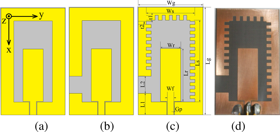
Fig. 1. Evolution of the proposed antenna: (a) grounded ring slot antenna (Antenna-1), (b) grounded G-shaped monopole antenna (Antenna-2), (c) proposed antenna (Antenna-3), and (d) fabricated prototype.
It is possible to generate CP by exciting two orthogonal modes having equal magnitude and that are 90° out of phase in time. This can be achieved by introducing an asymmetry in the antenna structure. To achieve the asymmetry in the ground plane, we introduce a discontinuity in the grounded rectangular ring by creating a gap of length L2 at a distance of L1 from the bottom edge of the ring and is shown in Fig. 1(b) (Antenna-2, a variant of [Reference Sze and Pan10]). To enhance the IBW and axial ratio bandwidth (ARBW), inner edge of the ring is corrugated (Antenna-3).
Figure 2 shows the simulated reflection coefficient and axial ratio for Antenna-1, Antenna-2, and Antenna-3. Antenna-1 is narrow band (and also poorly matched) and it is linearly polarized (AR > 40 dB). When a portion from the grounded ring is removed the antenna produces CP. The simulated reflection coefficient and ARBW for Antenna-2 are 35.06% (2.45–3.49 GHz) and 27.11% (2.55–3.35 GHz), respectively. In this paper, the input reflection coefficient bandwidth corresponds to the frequency band over which |S 11| ≤ −10 dB and the ARBW corresponds to AR < 3 dB. The bandwidth can be improved by incorporating the corrugation in the inner side of the grounded ring. The simulated reflection coefficient and ARBW for Antenna-3 are 43.1% (2.21–3.42 GHz) and 37.9% (2.2–3.23 GHz), respectively. From these results it can be concluded that, a significant improvement of 22.8 and 39.9%, respectively, is observed in the IBW and ARBW of Antenna-3 over Antenna-2.

Fig. 2. Simulated reflection coefficient and axial ratio for Antenna-1, Antenna-2, and Antenna-3 (axial ratio of Antenna-1 is > 40 dB).
The optimum dimensions of the proposed antenna shown in Fig. 1(c) are obtained for the maximum CP bandwidth (overlapping bandwidth of IBW and ARBW) as W g = 30, L g = 50, W s = 18, L s = 38, W r = 9.5, L r = 24.5, G p = 0.3, L1=10, L2=8, W f = 3, t1=2.3, and t2=1.5 (all dimensions in mm) using full wave simulation and iterative optimization.
Generation of circular polarization
For a better understanding of the mechanism of generation of circular polarization, the simulated vector surface current distribution obtained using full wave EM simulation for Antenna-3 (proposed antenna geometry) at 3 GHz at different time instants is shown in Fig. 3. The figure also shows the direction of dominant surface current (J s). As the phase changes from 0° to 270°, the dominant surface current (J s) rotates in counter clock wisedirection, and generates right hand circular polarization (RHCP) wave that is propagating in the + Z direction. Further, the inclusion of the corrugation in the ground plane increases the inner slot current path length, and hence the frequency band of operation decreases.

Fig. 3. Surface current distribution for the proposed antenna at 3 GHz for different time instants: (a) ωt = 0°, (b) ωt = 90°, (c) ωt = 180°, and (d) ωt = 270°.
Working mechanism and analysis
Thin wire approximation of Antenna-2 is used to understand the mechanism of operation of the antenna. The current on the antenna is assumed to be sinusoidal in nature and vanishes at the end points (i.e. at P 1, P 2, and P 3; see Fig. 4). The phase of the current is assumed to be constant if the arm length is less than 0.25λ. For longer arm lengths, a phase delay of e jkl is included in the current components where k is the propagation constant and is given by k = ω/c; ω isthe angular frequency and c is the velocity of EM wave in free space. Also, the gap, G p is very small compared to wavelength and therefore has been neglected in the analysis. The currents I 1 through I 7 (shown in Fig. 4) on each arm of the antenna can be expressed as follows:
 $$ \scale 94% { \bar{I_1} = I_o\sin\left[k\left(L_r-{L_g\over 2}+x'_4\right)\right]\hat{a}_x\semicolon\; \quad {-\left(L_r-{L_g\over 2}\right)} \leq x'_4 \leq {L_g\over 2} }$$
 $$ \scale 92% { \bar{I_2} = I_o\sin\left[k\left(-\left({L_g\over 2}-L1\right)+x'_3\right)\right]\hat{a}_x\semicolon\; \quad \left({{L_g\over 2}}-{L1}\right)\leq x'_3 \leq {L_g\over 2} } $$
 $$\bar{I_3} = I_o\sin\left[k\left({W_g\over 2}+L1-y'_3\right)\right]\lpar -\hat{a}_y\rpar \semicolon\; \quad 0 \leq y'_3 \leq {W_g\over 2}$$
 $$ \scale 88% { \bar{I_4} = I_oe^{-jky'_2 }\sin\left[k\left(L3+W_g+L_g+{W_g\over 2}+y'_2\right)\right]\hat{a}_y\semicolon\; -{W_g\over 2} \leq y'_2 \leq 0 }$$
 $$\bar{I_5} = I_oe^{\,jk\lpar {W_g}/{2}+{L_g}/{2}-x'_2\rpar }\sin\left[k\left(L_3+W_g +{L_g\over 2}+x'_2\right)\right]\hat{a}_x\semicolon\; \quad -{L_g\over 2} \leq x'_2 \leq {L_g\over 2}$$
 $$ \scale 85% { \bar{I_6} = I_oe^{\,jk\lpar W_g+L_g-y'_1\rpar }\sin\left[k\left(L3 + {W_g\over 2} - y'_1\right)\right]\lpar -\hat{a}_y\rpar \semicolon\; -{W_g\over 2} \leq y'_1 \leq {W_g\over 2} }$$
 $$ \scale 100% { \bar{I_7} = I_oe^{\,jk\lpar {L_g}/{2}+{3W_g}/{2}+L3+x'_1\rpar }\sin\left[k\left(-{L_g\over 2}+L3+x'_1\right)\right]\lpar -\hat{a}_x\rpar \semicolon\;} \cr & \quad {L_g\over 2}-L3 \leq x'_1 \leq {L_g\over 2} }$$
Fig. 4. Thin wire equivalent of Antenna-2.
The magnetic vector potential is given by,
 $$A_x={\mu\over 4 \pi} \int ^{}_{c} \lpar \bar I_1+\bar I_2+\bar I_5+\bar I_7\rpar {e^{-jkR}\over R} dx'$$
and,
 $$A_y={\mu\over 4 \pi} \int ^{}_{c} \lpar \bar I_3+\bar I_4+\bar I_6\rpar {e^{-jkR}\over R} dy'$$
where R is the distance between the source point (x′, y′, z′) and field point (x, y, z). The total electric field for the far-field region in the boresight direction (inthe + Z direction, at θ = 0°, ϕ = 0°) is given by,
 $$\bar E=E_x+E_y=-j\omega \lpar \bar A_x + \bar A_y\rpar $$
Evaluating the integrals in (8), (9) and substituting in (10), we get the electric field components (E x and E y) as,
 $$\eqalignno{E_x &={-j\omega\mu {e^{-jkr}\over 4 \pi r}}I_o\left[2+\lpar \cos\lpar kL_g\rpar -1\rpar e^{\,jk\lpar L_g+{3W_g}/{2}\rpar }\right.\cr & \quad -\cos\lsqb k\lpar L_g+W_g+L3\rpar \rsqb e^{\,jk\lpar {3W_g}/{2}}\rpar -\cos\lpar kL1\rpar \cr & \quad \left.+\cos\lsqb k\lpar L3+W_g\rpar \rsqb e^{\,jk\lpar {3W_g}/{2}\rpar }-\cos\lpar kL_g\rpar \right]}$$
 $$\eqalignno{E_y &={-j\omega\mu {e^{-jkr}\over 4 \pi r}}I_o \left[\vphantom{\left(k\left(L_g+L3+{3W_g\over 2}\right)\right)}\cos\lpar kL3\rpar e^{\,jk\lpar L_g+{W_g\over 2}\rpar }+\cos\lpar kL1\rpar \right.\cr & \quad -\cos\lpar kW_g+kL3\rpar e^{\,jk\lpar L_g+{W_g}/{2}\rpar }-cos\left(k\left(L1+{W_g\over 2}\right)\right)\cr & \quad \left.-\cos\lpar k\lpar L_g+W_g+L3\rpar \rpar +\sin\left(k\left(L_g+L3+{3W_g\over 2}\right)\right)\right]}$$
For the following dimensions of the antenna L1 = 0.062λ, L2 = 0.061λ, L r = 0.2λ, L g = 0.298λ, L3 = L g − L1 − L2, and W g = 0.24λ, the magnitude ratio of the electric field components (|E x|/|E y|) is equal to unity and the phase difference between them ( $\angle E_x - \angle E_y$) is 90°, which satisfies the condition for CP.
 $$\matrix{ L_g=0.297\lambda & L_g=0.298\lambda & L_g=0.299\lambda \cr {\vert E_x\vert \over \vert E_y\vert }=1.0 & {\vert E_x\vert \over \vert E_y\vert }=1.0 & {\vert E_x\vert \over \vert E_y\vert }=0.999 \cr \angle E_x - \angle E_y \approx {\pi\over 2} & \angle E_x - \angle E_y ={\pi\over 2} & \angle E_x - \angle E_y \approx {\pi\over 2} }$$
To validate the proposed antenna model, the thin wire model of the proposed antenna is simulated using method of moment (MoM). Figure 5 shows the normalized current magnitude on the wire. Figure 6 shows the phase of the current on the different segments of the antenna. It can be observed from Figs. 5 and 6 that the assumed current on antenna agrees well with the MoM simulation, except on the longer arm of the G-shaped antenna, where the assumed current is slightly different to that obtained using MoM simulation.
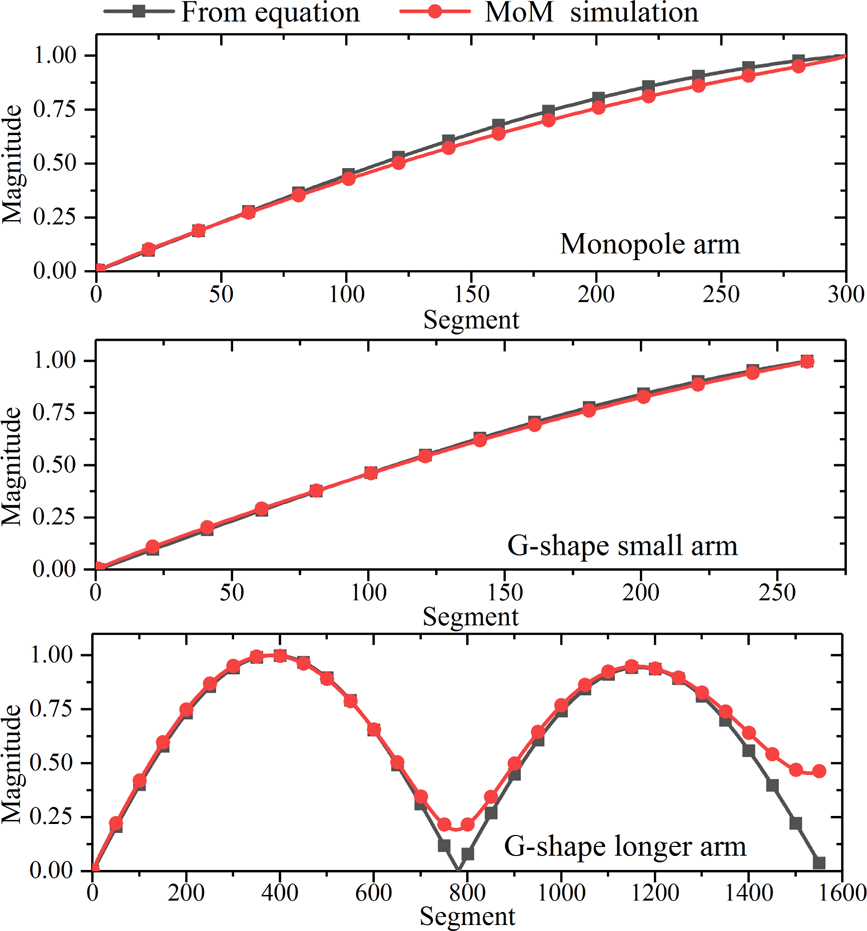
Fig. 5. Normalized surface current magnitude using thin-wire approximation and MoM simulation on different parts of the antenna (shown in Fig. 4).

Fig. 6. Surface current phase using thin-wire approximation and MoM simulation on different parts of the antenna (shown in Fig. 4).
Parametric analysis
The antenna characteristics are influenced by various geometrical parameters and to understand these effects, a parametric analysis has been performed using full wave simulation. The dimensions of the monopole antenna, corrugation in the inner edge of the ring, and discontinuity in the grounded ring have been varied and their effects are discussed below.
Effect of monopole width, W r
It can be observed from Fig. 7(a), that the lower and upper band edge frequencies corresponding to IBW and ARBW are less affected by W r. However, upper band edge frequency, corresponding to |S 11| = −10 dB, increases with W r and the mid-band axial ratio gets worse. The maximum bandwidth can be achieved for W r = 9.5 mm.

Fig. 7. Effect of (a) W r and (b) L2, and (c) t2 on reflection coefficient and axial ratio.
Effect of discontinuity in the grounded ring
The effect of changing the length L2 of the gap in the ground plane on the input reflection coefficient and axial ratio is shown in Fig. 7(b). As L2 increases, we observe very little change in the lower band edge of the reflection coefficient, however, the upper band edge shifts to higher frequency, resulting in slight improvement in the input IBW.
The effect of increasing L2 has a more dominant effect on the ARBW. Without the gap in the ground (Antenna-1, when L2 = 0 mm), the antenna is linearly polarized and hence the axial ratio is not plotted. As L2 increases, both lower and upper band edge frequencies shift toward the higher side, along with an increase in the bandwidth. This is also accompanied by the deterioration of the mid-band level of the axial ratio. Thus, it is observed that best AR bandwidth is obtained for L2 = 8.1 mm.
Effect of corrugation in the grounded ring
The geometrical parameter t1 and t2 define the corrugated structure and they show similar effect on the reflection coefficient and ARBW. For brevity, only the effect of t1 is discussed here and shown in Fig. 7(c). On increasing t1, both the input IBW and ARBW increase until t1 = 2.3 mm and then reduces. The maximum CP bandwidth can be achieved for t1 = 2.3 mm and t2 = 1.5 mm.
Design guideline
Based on the parametric analysis, the empirical design guidelines are presented in this section for Antenna-2 and Antenna-3. The design of the corrugated G-shaped grounded ring slot antenna is a two-step process.
In the first step, some of the important dimensions of Antenna-2 are specified in terms of wavelength (λc) corresponding to the center frequency as follows: L g ≈ 0.385λc, L1 ≈ 0.05λc, L2 ≈ 0.06λc, L f ≈ 0.2λc, W g ≈ 0.25λc, and L3 = L g − L1 − L2. The antenna dimensions are then optimized to achieve maximum bandwidth using an iterative procedure.
In the second step, the corrugation is introduced in Antenna-2 as shown in Fig. 1(c) and the dimensions t1 and t2 are optimized for maximum bandwidth.
Experimental results
The proposed CPW-fed monopole antenna with corrugated G-shaped grounded ring (Antenna-3) for wideband CP, shown in Fig. 1(c), is fabricated and its performance is validated by measurement. The photograph of the fabricated antenna is shown in Fig. 1(d). An SMA connector was used at the input port to feed the antenna. Agilent E5071C VNA was used to measure the input impedance of Antenna-3. All radiation characteristics viz. radiation pattern, gain, and axial ratio were measured in an anechoic chamber.
The measured and simulated reflection coefficient (|S 11|) of the proposed antenna is shown in Fig. 8(a). The measured and simulated reflection coefficient bandwidth (|S 11| < −10 dB) of the proposed antenna are 47.9% (2.13–3.47 GHz) and 43.1% (2.21–3.42 GHz), respectively. The measured axial ratio is also compared with the simulated results in Fig. 8(b). The measured 3 dB ARBW is 37.6% (2.22–3.25 GHz) and the simulated AR bandwidth is 37.93% (2.2–3.23 GHz). The measured and simulated overlapping CP bandwidth (the common bandwidth with AR < 3 dB and |S 11| < −10 dB) of the proposed antenna is 37.6 and 37.93%, respectively. The measured and simulated gain of the antenna is shown in Fig. 8(b), which is measured in the broadside (+ Z direction) direction. The mismatch between the measured and simulated results could be attributed to the tolerances in the fabricated antenna and the cable interacting with the small ground plane of the antenna.
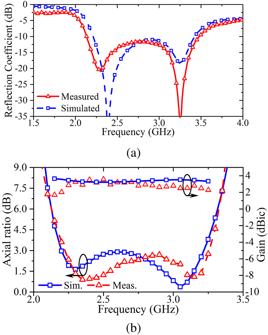
Fig. 8. Measured and simulated reflection coefficient, gain and axial ratio for proposed antenna (Antenna-3).
Figure 9 depicts the measured and simulated normalized radiation patterns in both XZ- and YZ-plane at 2.4 and 3 GHz. The antenna radiates RHCP wave inthe + Z direction and LHCP in the − Z direction. There is a good agreement between the measured and simulated results.

Fig. 9. Normalized measured and simulated radiation pattern in (a) XZ-plane for 2.4 GHz, (b) XZ-plane for 3 GHz, (c) YZ-plane for 2.4 GHz, and (d) YZ-plane for 3 GHz.
A comparison of the proposed antenna with some recently reported circularly polarized antennas is summarized in Table 1. It can observed that the proposed CP antenna has wider ARBW and compact in size.
Table 1. Comparison of previously reported antenna geometries.

λL corresponding to lower band edge frequency for AR < 3 dB.
Conclusion
A wideband circularly polarized monopole antenna has been presented and implemented. The monopole antenna placed inside a corrugated G-shaped ground is able to generate CP over a wideband of frequencies. The CP mechanism was described using surface currents and mathematically verified using thin wire equivalent of the proposed antenna. The measurement shows that the proposed antenna has − 10 dB reflection coefficient bandwidth of about 1350 MHz or 47.91% (2.13–3.48 GHz) and a 3 dB ARBW of about 1030 MHz or 37.6% (2.22–3.25 GHz). The proposed antenna is compact in size and having higher ARBW than some of the earlier published structures.
 Kapil Saraswat received hisM.Tech. degree fromthe Indian Institute of Technology Roorkee, India in 2013 in electronics and communication engineering, and his Ph.D. degree fromthe Indian Institute of Technology Kanpur, India in 2019 in electrical engineering. His current research interests include CP antennas, reconfigurable antennas, RFID, computational electromagnetics, tunable/reconfigurable and programable metasurfaces, etc.
 Trivesh Kumar received his Ph.D. in electrical engineering from the Indian Institute of Technology Kanpur, India. He is currently an Assistant Professor inthe Department of Electrical Engineering, Indian Institute of Information Technology, Design and Manufacturing (IIITDM), Jabalpur, India. His current research interests include circularly polarized antennas and analysis, microwave measurements, radio-frequency identification, etc.
 A. R. Harish received his Ph.D. in electrical engineering from the Indian Institute of Technology Kanpur, India. He was with Com Dev Wireless, Dunstable, UK, and was a visiting faculty at the University of Kansas. He is currently a professor with the Department of Electrical Engineering, Indian Institute of Technology Kanpur. His current research interests include antenna analysis, microwave measurements, microwave circuits, radio-frequency identification, and computational electromagnetics.


