I. INTRODUCTION
Antennas for wearable applications can be classified into three different types. The first type are antennas having rigid dielectric substrates that would occupy a small area rendering it useful for wearable applications [Reference Sanz-Izquierdo, Miller, Batchelo and Sobhy1]. The second type are the flexible antennas with a flexible substrate constituting the printed circuit board [Reference Raad, Abbosh, Al-Rizzo and Rucker2, Reference Khaleel, Al-Rizzo, Rucker and Mohan3] and the third type are the textile antennas that are composed of cloth fabric itself [Reference Osman, Rahim, Samsuri, Salim and Ali4].
The form factor and area occupied by the rigid dielectric antenna restricts the use of these antennas for wearable applications. Since the dimensions of the antenna made using the rigid boards have to be kept small to attach them on clothes, designing antennas at lower GHz range frequencies and obtaining a large operating bandwidth is a difficult task. If larger antennas are used, the movement of users is hindered. Flexible antennas with a substrate of foam or any flexible polymer substrates are difficult to integrate with the clothing of a person as they differ from the clothing material surrounding it. The third type of wearable antenna known as the textile antenna has the conductive and/or non-conductive material of the antenna, as a part of the fabric of regular clothing.
Proper integration of communication antennas into regular cloth fabric has many uses, which would benefit almost all smart clothing applications. One major use would be in rescue operations where communication components and associated electronics can be a part of the cloth fabric with little or no increase in the weight. This research aims at proposing a complete integration of antennas into the regular cloth fabric, which would enable the users to go about their daily duties without difficulty. Another potential use of this type of technology would be its use in building a collision avoidance system for the visually impaired [Reference Szeto and Sharma5].
The use of different substrates for construction of textile antennas has been previously studied in [Reference Sankaralingam and Bhaskar6]. Various methods for the production of these wearable antennas are also given in the literature. For example, copper foils could be attached to fabrics to form textile antennas [Reference Esther, Malathi and Alsath7]. Deposition of conductive inks using screen printing technique, electroplating the ordinary fabric with conductive material, knitting of these antennas, and also embroidery have been studied [Reference Graham8].
In [Reference Sanz-Izquierdo, Huang and Batchelor9] buttons in jackets have been converted into antennas. [Reference Locher, Klemm, Kirstein and Troster10] Explains the use of three different coated fabrics that can be used as the conducting regions of the planar antenna. Using conductive paints and inks, flexible antennas have also been fabricated through screen or inkjet printing [Reference Leng, Huang, Chang, Chen, Abdalla and Hu11, Reference Koji, Kuniaki, Keiji and Haruichi12]. Although the screen printing technique is faster compared to weaving, the requirement of a flexible conductive paste that could detach itself during regular use is the major drawback of the method. There might be a requirement for a protective layer above the ink or paste over the fabric. The paste could crack or peel which would compromise the satisfactory performance of antennas. Likewise, embroidery of the antenna layers would cause an elevated portion, increasing the risk of disconnection or detachment [Reference Roh, Chi, Lee, Tak, Nam and Kang13]; but embroidery can be done using advanced machinery which could enhance repeatability in production [Reference Kiourti and Volakis14]. The antenna fabrication proposed in this manuscript was done keeping in mind the need for a completely integrated textile antenna. The designed antenna was also required to be a part of the original structure of the fabric and not protrude as an attachment. This would render an unobtrusive operation of these antennas. Hence, in the proposed work, weaving was the method used for fabric production [Reference Behera and Rajesh15]. The proposed technique of textile antenna production also eliminates the need for fastening or attachment of the different layers of the planar antenna structure together. Access to production looms was also another reason for choosing weaving for fabric production.
The fabrication of the electro-textile antenna is explained in Section II. Section II also describes the salient features of the fabricated textile antenna. The results and the discussions for the multilayered weave antenna are presented in Section III.
II. FABRICATION OF A MULTILAYER WEAVE ELECTRO-TEXTILE ANTENNA
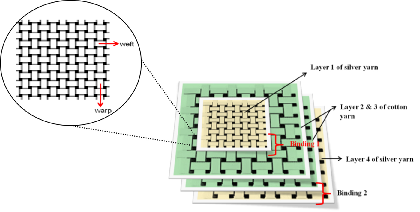
Weaving consists of interleaving yarn or thread, one in the vertical direction (warp thread) and another in the horizontal direction (weft thread). For every layer of cloth fabric, the interlocking of warp and weft threads would be done. To make cloth fabric with multiple layers, the weft yarn would pass through the various layers of warp thread and bind them together as shown in Fig. 1. This type of weaving is mentioned in literature as three-dimensional type of weaving [Reference McIlhagger and Archer16].These weft threads that are cuts in the weave pattern that disrupt the layers and bind them together are called binders. However, these binders would behave as a short circuit in an antenna configuration. In order to fabricate an integrated textile antenna, there was a need to have layers that were separated from each other to prevent shorting of the radiating patch and the ground plane. To do these, four layers of fabric were proposed as shown in Fig. 2. The substrate of the patch antenna would use two layers (instead of one) of dielectric fabric material and the top and bottom layers would be of conducting yarn. The binding would be done only on the edges of the layers. Layers 1 and 2 would be bound by weft yarn at the edge of layer 1. Layer 1 now forms the top radiating patch. Layers 2 and 3 are bound at their edges and both layers together constitute the substrate of the antenna. Layer 3 is bound with layer 4 at the edges where layer 4 becomes the ground plane that is completely isolated from the radiating patch. This can create independent fabric layers. In Fig. 1, the weft threads bind the various layers throughout the cloth fabric, while in the proposed method, the weft threads cross all the four layers only at the edges of the patch and substrate.

Fig. 1. Conventional multilayered weave textile antenna [Reference McIlhagger and Archer16].

Fig. 2. Proposed multilayered weave textile antenna.
A weaving loom was specially setup to weave four independent layers according to the proposed layering and binding. A trial run was first conducted for the modified set up, by using simple cotton yarn for all four layers. As the technique proved to be satisfactory, the set-up of the loom is reset with cotton yarn for the two middle layers and pure silver yarn for the top and bottom layers.
The silver yarn could be replaced by any conducting yarn. However, the thickness of the yarn should be taken into consideration, which would determine how much yarn should be used to set up the warp/weft thread to weave per unit length of antenna. The proposed layering of the weaves is depicted in Fig. 2. Weft yarn is wound in instruments called as boat shuttles (cotton for the middle layers, silver for the top and bottom layers) and used to weave the proposed multilayer textile antenna.
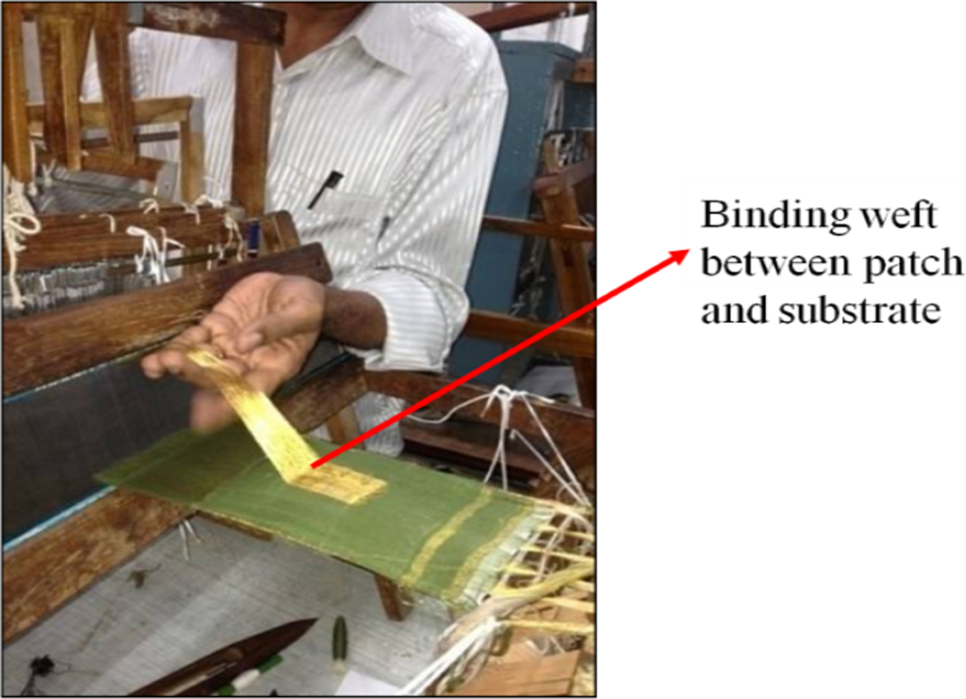
Binding weft is run along the edges of the patch to the cotton layer beneath it. Similarly binding weft would hold the layer 3 of cotton to the ground plane made of silver along the edges. The production of the textile antenna on a table loom is shown in Fig. 3.

Fig. 3. Prototype building of the multilayered weave textile antenna.
The conductivity over different parts of the top and bottom conductive portions was checked. Since conductive yarn was used for both the warp and weft directions, these layers were completely conductive with no non-conductive regions.
The novel features of the fabricated fully textile antenna is that conductive threads woven in the warp as well as weft are used to produce the conductive patch and the ground plane. This makes the antenna completely wearable. Four-layer weaving is used to produce three layers of different material for the textile antenna (conductor–dielectric–conductor). The substrate woven from simple cotton threads makes the textile antenna more flexible and wearable. The textile antenna is now totally integrated and hence eliminates the need for positioning and fastening of the components. The proposed prototype also offers complete and easy integration with clothing. Full integration of the textile antenna to the point of production is achieved by eliminating the tasks of positioning and fastening of the components and layers of the antenna. The feeding is also appropriately chosen for wearable applications.
Due to the seamless integration into clothing, the antenna would be useful in defense to enhance military camouflage. Low-cost production using a basic weaving jacquard and enhanced flexibility of the textile antenna are the major advantages in the proposed design.
III. RESULTS
The dimensions of the top layer of conductive fabric are calculated through the transmission line model [Reference Balanis17].The length and width of the patch are found to be 55 and 48 mm, respectively. The antenna is designed at the resonant frequency of 2.45 GHz for Wireless Local Area Network (WLAN) protocol. Simulation of the multilayered antenna with a coaxial probe feed as shown in Fig. 4 is also run in CST Microwave Studio for verification of the structure. The simulation parameters set for the material used as the ground plane and radiating patch is silver with permeability μ = 1, electrical conductivity = 6.3012e007 [S/m]. For the substrate, cotton fabric material is defined with a permittivity of 3.18 and loss tangent 0.04 as taken from literature [Reference Florin and Adriana18, Reference Salvado, Loss, Gonçalves and Pinho19].Using the dimensions of the woven antenna, a simulation is run and the structure resonated at 2.457 GHz with |S 11| of −20.62 dB. The gain and radiation efficiency of the designed antenna are 8 dBi and 0.9154, respectively.
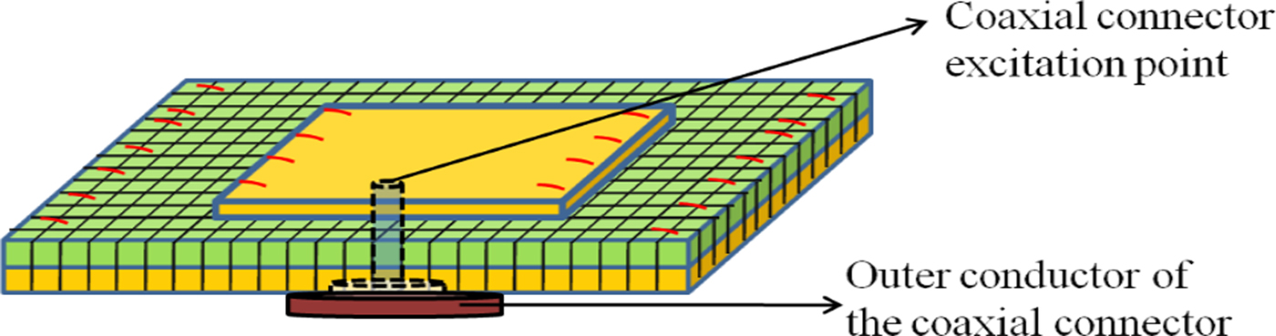
Fig. 4. Simulation model with coaxial feeding of the multilayered weave textile antenna.
The prototype that is built is then excited using a coaxial feed (after calculation of the feed point according to the dimensions of the patch). The prototype is shown in Fig. 5. The measurement is done using Agilent's portable network analyzer and the comparison of the reflection coefficient characteristics is done in Fig. 6. The resonant frequency of the designed antenna is at 2.43 GHz with a |S 11| of −18.62 dB.
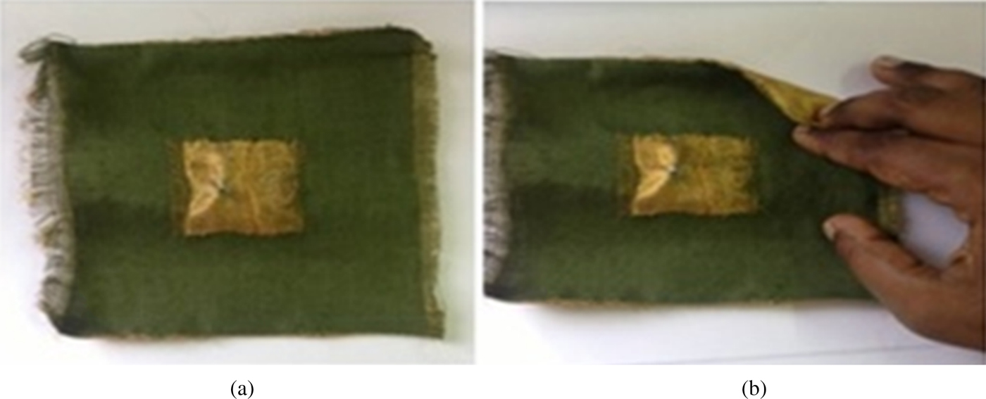
Fig. 5. (a) The multilayered weave textile antenna. (b) The multilayered weave textile antenna showing ground plane.
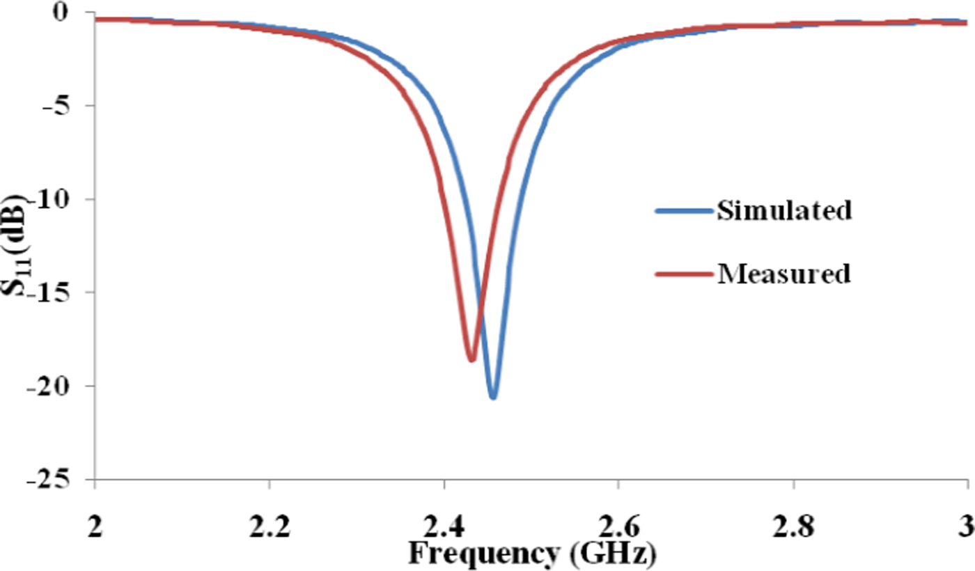
Fig. 6. S 11 of the simulated and measured multilayered weave antenna.
The proposed technique for production of textile antennas can be extended to incorporate any planar design of patch antennas, frequency selective surfaces, and electromagnetic band gap (EBG) surfaces [Reference Huang20, Reference Baisakhiya, Sivasamy, Kanagasabai and Periaswamy21]. To test the radiation capability of the proposed design, the E-plane and the H-plane radiation patterns have been measured. The measurement setup is shown in Fig. 7.

Fig. 7. Radiation pattern measurement setup of the multilayered weave antenna.
For measurement of radiation pattern, a standard gain horn is used as the transmitting antenna, while the fabricated prototype acts as the receiving antenna. The fabricated antenna is placed on a software-controlled turn table. A network analyzer is connected between the transmitting and receiving antenna and is interfaced with the software that plots the radiation pattern. The orientation of the receiving antenna is changed to measure E and H radiation patterns.
The E-plane and the H-plane radiation patterns at 2.43 GHz for both simulation and measurement are shown in Fig. 8. The full ground plane reduces the presence of back lobes in the radiation pattern as can be seen from Fig. 8. It is known that E-plane edge diffractions are stronger than those of the H-plane, and hence due to destructive interference, the back lobe is lesser in the E-plane compared with the H-plane [Reference Ameelia and Malathi22, Reference Aboserwal, Constantine and Craig23].
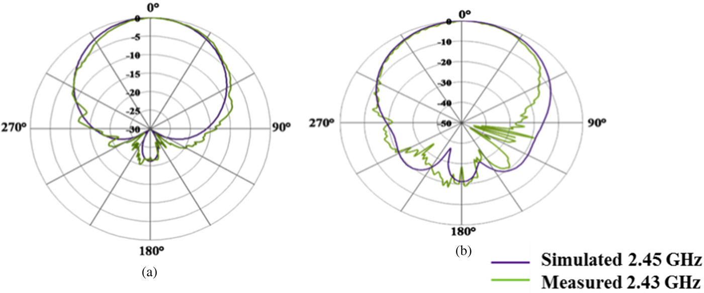
Fig. 8. (a) E-plane pattern at 2.43 GHz. (b) H-plane pattern at 2.43 GHz.
The measured and simulated parameters of the proposed antenna are tabulated in Table 1. Ideally, the reduced measured gain should have resulted in a narrower beamwidth. There could be several reasons for the mismatch between the simulated and measured gain-beamwidth discrepancy. One could be due to the various approximations induced during simulation of the proposed antenna like the ground plane in the fabricated prototype would not ideally be a homogenous conductive plane as is defined during simulation. The same is true for the radiating patch too. The ground plane becomes a grid-like structure in the fabricated prototype. Any change in aperture could cause a change in the efficiency of the antenna. Literature also states that when there are more sidelobes, gain and beamwidth might not always be inversely proportional [Reference John24]. As it can be seen, there is significant amount of energy distributed in the back lobes and this could have been a contributing factor as well. The gain along the bore sight direction of the antenna is calculated using the formula shown in [Reference Balanis17].
Table 1. Parameters of the proposed completely integrated textile antenna.

The gain of the fabricated textile antenna was calculated using it as the receiving antenna of unknown gain. A standard gain antenna of gain 11.5 dBi was used for the transmitting antenna. The distance (R) between the two antennas was kept constant at 1.6 m. The power transmitted from the standard gain antenna was kept at 0 dBm. Wavelength at the operating frequency was calculated as 0.12337 m. The gain of the receiving antenna in the case of the fabricated multilayered weave textile was found to be 1.0624 dBi at 2.43 GHz. The prototype was fabricated using a simple table loom used for weaving regular cloth fabric. The weaving was manually done, and hence the weave structure would have caused entrapment of small air gaps between the weaves. Hence, the ground plane in the fabricated prototype would not ideally be a homogenous conductive plane as is defined during simulation. The same is true for the radiating patch too. This could be the major cause of difference between the simulated and measured gain. Measurement induced errors could also be a contributing factor. The plot of measured gain versus the frequency is shown in Fig. 9.
Fig. 9. Gain versus frequency plot for the fabricated antenna.
A) Specific absorption rate evaluation
As the antenna proposed here would work close to the human body, it is necessary that the impact of the antenna on the human body has to be carried out [Reference Kamalaveni and Ganesh Madhan25]. Specific absorption rate (SAR) calculation has to be done to ensure that little to no harm is done to the person wearing the antenna. An SAR limit of 2 W/kg averaged over any contiguous 10 g head tissue is recommended by the Council of European Union for the general public [Reference Mhaske, Kulkarni and Tayade26, Reference Vladimir27].
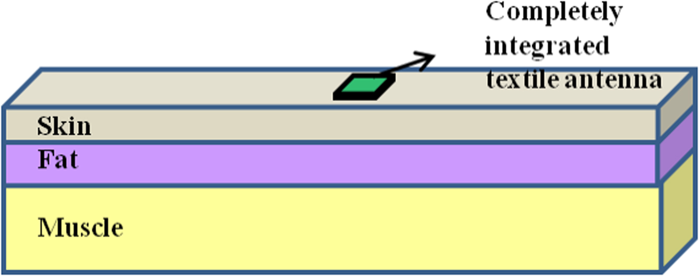
Body models that define various body tissues replicating the presence of lossy human tissue are available. There are detailed body models, which include various organs of the body. However, detailed body models demand higher run time while exhaustively using up computational resource. Simplified human body models are presented in literature such as the cylinder model and the rectangular model, which is defined using dielectric constant and conductivity [Reference Vivek and Bharat28]. The rectangular model of body is used to study the proposed antenna as it is known to give good agreement with measurements.
The model is depicted in Fig. 10 where the thickness of skin, fat, and muscle varies according to the different regions of the body. Simulation is done on rectangular body models that approximated the five regions of the human body namely arms, biceps, chest, back, and waist.

Fig. 10. Rectangular human body phantom used for SAR computation.
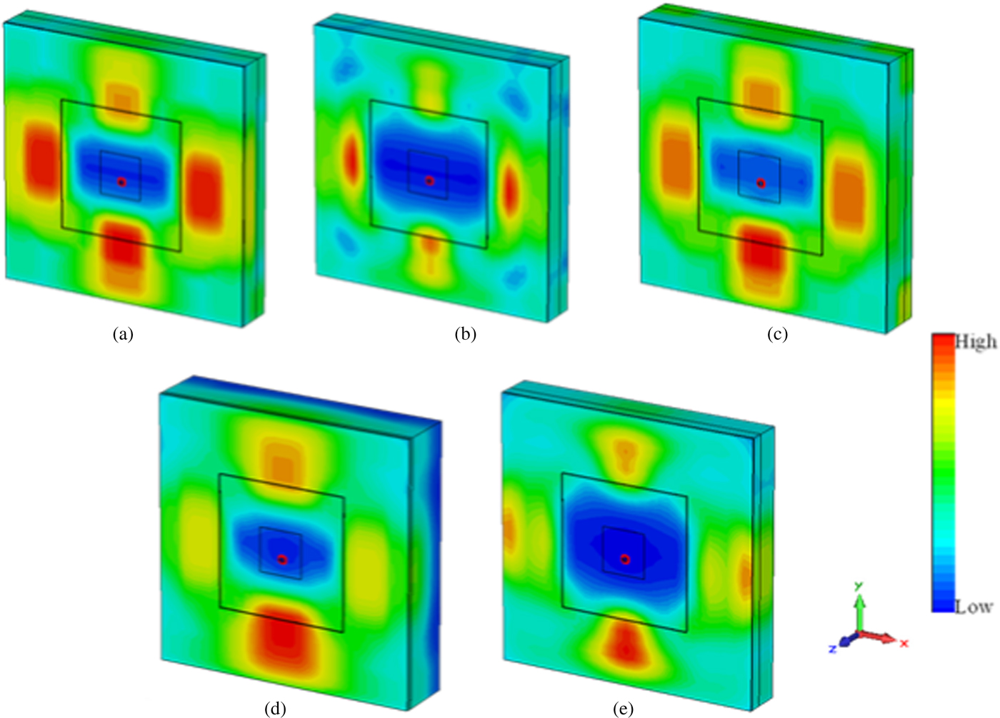
The permittivity, loss tangent, and density for the different tissues are defined as shown in Table 2. The thickness of skin, fat, and muscle at different regions of the body is shown in Table 3. A truncated human body model shown in Fig. 11 shows the results for SAR computed at various regions of the body. Figure 11 shows the simulated SAR (a) at the arms, (b) at the biceps, (c) at the chest, (d) at the back, and (e) at the waist regions of the human body.

Fig. 11. SAR computed at various regions: (a) arms, (b) biceps, (c) chest, (d) back, (e) waist.
Table 2. Electrical properties of tissues [Reference Peter and Yang29] at 2.45 GHz.
Table 3. Tissue thickness at different regions of the body.
The results of the computed SAR values are tabulated in Table 4. The computed SAR as shown in Table 4 fall well within the specified range since the antenna employs a full ground plane that blocks backward radiation. This makes the proposed antenna design suitable for wearable communications as the SAR requirements are satisfactorily met. The SAR value for the proposed structure is on an average 0.01 W/kg, which is well below the standard set (federal communications commission – 1.6 W/kg). For wearable communication, it is required that the antenna should induce a very minimum SAR [Reference Nacer, Maxim and Ronan30, Reference Elias, Samsuri, Rahim, Othman and Jalil31], the proposed antenna structure would be well suited for it. The fact that the antenna is made exclusively from cloth fabric makes it a suitable choice for on-body communication.
Table 4. SAR computed at different regions of the body.

The uniqueness of the proposed fabrication methodolgy when compared with similar ones in the literature [Reference Xu, Yao and Zhao32, Reference Jung, Yong and Tae33] is depicted in Table 5.
Table 5. Comparison of the proposed fabrication method of textile antenna with literature.

IV. CONCLUSION
A unique method for fabrication of electro-textile antenna was presented in this paper. The proposed structure was completely integrated at the point of production. The method involved the design of a multilayered woven textile antenna that showed good impedance matching at the 2.4 GHz band. The radiation pattern and gain for the structure were measured and conformed to acceptable values. SAR analysis was done using simulation at the resonant frequency, to check conformation of the antenna to existing standards. On an average, SAR for the designed antenna was about 0.01 W/kg. The proposed technique for production of textile antennas would also be ideally suited for the fabrication of various planar structures like patch antennas and EBG surfaces.
The same technique could be extended to incorporate slots or slits either in the top or bottom conductive layers to introduce additional resonances, increase the impedance bandwidth, or improve impedance matching. Hence, the proposed novel fabrication technique would find wide scope in the design of planar radiating components.
 Esther Florence Sundarsingh is an Associate Professor in the Department of Electronics and Communication Engineering at Sri Sivasubramaniya Nadar College of Engineering, India. Her research interests include design and analysis of microwave components like antennas for wearable application, application of flexible substrates in the design of microwave components.
 Malathi Kanagasabai is an Associate Professor in the Department of Electronics and Communication Engineering, College of Engineering Guindy, Anna University, Chennai, India. Her research interests include microwave communication, planar transmission lines, planar antennas, and signal integrity analysis in high-speed systems.
 Vimal Samsingh R serves as an Assistant Professor in the Department of Mechanical Engineering at Sri Sivasubramaniya Nadar College of Engineering, Chennai, Tamil Nadu, India. His research interests include development of sensors for non-destructive testing, material testing using microwave sensors and composite material development.