


Introduction
Ultra-wideband (UWB) technology is one of the emerging technologies that captured the attention of scientists and industry in the world. UWB systems have great consideration for modern communication applications. They have attracted more attention in the past few years [Reference Kumar, Khokle and Krishna1] due to their high performances, such as higher data rate and wide impedance bandwidth [Reference Liu, Wang and Qin2]. The UWB technology was authorized by the federal communication commission to use a new spectrum from 3.1 to 10.6 GHz with effective isotropic radiated power <−41.3 dBm/MHz in commercial applications [3]. The UWB technology is characterized by several advantages, including a wide impedance bandwidth, very-low-power spectral density, considerable channel capacity, and excellent immunity to multi-channel interference [Reference Hammache, Messai, Messaoudene and Denidni4–Reference Chu and Mao6].
An antenna is an essential part of any wireless communication system. In UWB systems, the antenna must have a broad bandwidth and a stable gain in the whole operating frequency range. The innovation and development of communication applications require antennas of very compact size to miniaturize these systems [Reference Bekasiewicz and Koziel7]. Various techniques have been proposed in the literature to design antennas with compact size, such as using shorting pins, introducing a shorting wall, and creating a defected ground substrate in the ground plan [Reference Yang, Xi, Zhao, Wang and Shi8]. The integration of slots in the ground plan is an effective solution to reduce the antenna size; this technique is based on etching different forms of slots to lengthen the current path for minimizing the resonance frequency and reducing the dimensions of the antenna [Reference Sim, Chung and Lee9]. Several antenna designs for reducing the size, enhancing the impedance bandwidth, and improving the radiation characteristics have been reported in [Reference Hammache, Messai, Messaoudene and Denidni4, Reference Bekasiewicz and Koziel7, Reference Yang, Xi, Zhao, Wang and Shi8, Reference Yang, Xi, Zhao, Tan, Yuan and Wang10–Reference Srivastava and Mohan13]. The reduction size of the antenna is extremely important to integrate it in miniaturized systems for indoor applications, such as the Internet of things and wearable device [Reference Srivastava, Mohan and Chakrabarty14, Reference Bekasiewicz and Koziel15].
In this paper, a very small and compact stepped slot antenna for UWB applications is presented. The proposed antenna has a very compact size (136 mm2). The antenna is formed with a simple design where a stepped slot is integrated into the ground plane to obtain a UWB impedance bandwidth and reduce the antenna size. The proposed antenna is fed by a microstrip line with cutting in the middle to improve the matching of the antenna. The position of the microstrip line has a critical role to obtain a good impedance bandwidth. The antenna has the dimensions of 17 mm × 8 mm × 1.27 mm. A comparison study was performed to show the superiority of the proposed antenna compared with previous works in the literature. From this study, it can be clearly seen that the proposed design is simple and provides a good performance in terms of compactness compared with previous works. This work is mainly inspired from our previous work cited in [Reference Hammache, Messai, Messaoudene and Denidni4]. The results obtained in terms of reflection coefficient and radiation pattern have a good agreement with the simulated ones.
Antenna design
UWB slot antenna
Figure 1 presents the design and the dimensions of the proposed compact UWB slot antenna. The antenna is fabricated on RT/duroide 6006 substrate with dielectric constant ɛr = 6.15, dissipation factor tanδ = 0.0027, and thickness h = 1.27 mm; the antenna size is 17 mm × 8 mm; this antenna is considered among the smallest size of antennas realized in the UWB slot antenna domain. The proposed antenna is realized by integrating additional elementary slots in the ground plane, each elementary slot has a matching point in the UWB range. The assembly of these elementary slots provides a wide impedance range. However, it is necessary to adjust the position of the microstrip line to obtain a UWB bandwidth. For the feeding of the proposed antenna, a 50 Ω microstrip line is used with cutting in the middle to improve the matching of the proposed antenna. The stepped slot is positioned near the top of the microstrip line to obtain the maximum coupling between them. The optimized dimensions of the proposed antenna are presented as follows: L = 17, W = 8, h = 1.27, Wf = 1.8, Lf = 13.75, Wf 1 = 1, Lf 1 = 1.25, W 1 = 3.3, W 2 = 0.7, W 3 = 0.8, W 4 = 0.7, W 5 = 0.6, W 6 = 0.7, W 7 = 0.4, L 1 = 7.65, L 2 = 1.05, L 3 = 4.75, L 4 = 3.5, L 5 = 4.75, L 6 = 3.5, L 7 = 4.75, D = 4.9.
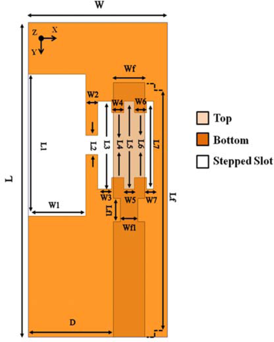
Fig. 1. Geometry, design, and dimensions of the proposed antenna.
The evolution of the design and the different steps to realize the compact UWB slot antenna is presented in Fig. 2. In the first step for Antenna 1 in Fig. 2(a), an open-ended rectangular slot (R-slot) is integrated into the ground plan; this structure generates a single resonance in the range between 4.2 and 6.25 GHz. In Fig. 2(b) for Antenna 2, an open-ended T-shaped slot is integrated into the ground plane. For this case, a frequency band between 2.98 and 3.55 GHz is obtained by Antenna 2. For the third step in Fig. 2(c), a simple stepped slot is etched in the back side of the antenna. A wide impedance bandwidth between 6.79 and 10.1 GHz is achieved by the simple stepped slot in Antenna 3. The assembly of the elementary slots in Antenna 1, Antenna 2, and Antenna 3, respectively, provides a wide impedance bandwidth. The proposed antenna, shown in Fig. 2(d), provides a UWB bandwidth using stepped slots. All the results of the different steps to obtain a UWB slot antenna are presented in Fig. 3. For Antenna 4, an impedance bandwidth between 3.1 GHz and more than 12 GHz is observed.

Fig. 2. Different steps to obtain UWB slot antenna: (a) Antenna 1, (b) Antenna 2, (c) Antenna 3, and (d) Antenna 4.

Fig. 3. Simulated reflection coefficients of different four steps to obtain UWB slot antenna.
Parametric study
A parametric study is carried out on the antenna to illustrate how this antenna obtains a UWB bandwidth. In this study, four parameters are chosen. Figure 4 presents the effect of the integration of R-slots in the antenna. From Fig. 5, it is observed that the antenna without R-slots covers the frequency range between 3.5 GHz and more than 12 GHz, and for the antenna with R-slots, the antenna covers the frequency band between 3.1 GHz and more than 12 GHz. It can be seen that there is a difference between the antenna without and with R-slots, whose operating frequency is improved from 3.5 to 3.1 GHz at the low frequency. Thus, the R-slots have a critical role to improve the edge of the impedance bandwidth in the low frequency.

Fig. 4. Integration of rectangular slots (R-slot) in the stepped slot: (a) without R-slots and (b) with R-slots.

Fig. 5. Comparison reflection coefficients of UWB slot antenna with and without rectangular slots (R-slots).
The proposed antenna is fed by a microstrip line with cutting in the middle. Figure 6 presents the comparison between the reflection coefficient of the proposed antenna with Lf1, Wf1 and without Lf1, Wf1. Before creating the defect in the microstrip line, the bandwidth is comprised of frequency between 3.1 and 12 GHz, with a frequency band between 5.25 and 8.15 GHz when the S 11 is <−10 dB. After modifying the microstrip line, a UWB bandwidth is obtained from 3.1 GHz to more than 12 GHz when the S 11 is <−10 dB and the antenna matching is improved by creating Lf1 and Wf1.

Fig. 6. Comparison reflection coefficients of the proposed antenna without Lf1, Wf1 and with Lf1, Wf1.
A parametric study was performed to clarify that the position of the feed line has an important role in matching the proposed antenna, by making the best coupling between the feed line and the stepped slot integrated into the ground plane. The parameter D is chosen to show the effect of the position of the feed line. Figure 7 presents the variation of reflection coefficient by changing the position of the feed line. An important variation is observed by changing the value of D, which leads to improve the matching of the antenna, and the best value for good matching is in D = 4.9 mm. Figure 8 presents a parametric study of another essential parameter in the proposed antenna design, the length of L 2, which has a great effect on improving the bandwidth of the antenna at higher frequencies. As shown in Fig. 8, for the first value of L 2, the bandwidth of the antenna is between 3.1 and 9.3 GHz. In the other cases, the bandwidth is decreased when the value of L 2 is increased. The optimal value is L 2 = 1.05, which leads to cover the UWB bandwidth. The operating frequency is improved by changing the value of L 2, from 9.3 GHz for L 2 = 4.75 to more than 12 GHz for L 2 = 1.05 at the high frequency.

Fig. 7. Simulated reflection coefficients of UWB slot antenna with different values of D.

Fig. 8. Simulated reflection coefficients of UWB slot antenna with different values of L 2.
Numerical results and discussion
The experimental and the simulated results of the very compact UWB slot antenna are presented in this section. The proposed antenna is fabricated on RT/duroide 6006 with ɛr = 6.15, tanδ = 0.0027, and h = 1.27 mm, a photo of the fabricated proposed antenna is presented in Fig. 9. The simulated results are realized by Computer Simulation Technology (CST) simulator, and the measurements of S-parameters were performed by using Agilent 8722ES network analyzer.

Fig. 9. Photography of very compact stepped slot antenna for UWB applications.
The measured and simulated reflection coefficients of the proposed antenna are presented in Fig. 10. A good agreement is shown between the measurements and the simulated results. For the measurement results, a UWB range between 3.05 GHz and more than 12 GHz is obtained, and for the simulated results, an impedance bandwidth of the proposed antenna is also obtained between 3.1 GHz and more than 12 GHz.

Fig. 10. Comparison between simulated and measured reflection coefficient of compact stepped slot antenna for UWB applications.
Figure 11 shows a comparison between the measured and simulated normalized radiation patterns of the very compact stepped slot antenna for UWB applications at 3.3, 5.5, and 9 GHz, respectively, in the H-and E-planes. From this figure, it is observed that the proposed antenna has an omnidirectional radiation pattern in the H-plane (xz-plane) for the proposed frequencies excepted in the second frequency at 5.5 GHz, some deformation is observed, this is due to the measurement effect and the asymmetry of the proposed antenna, because the feed line is shifted to the right side of the antenna. In addition, the radiation pattern in this frequency is quasi-omnidirectional. For the E-plane (yz-plane), the proposed antenna has a bidirectional radiation pattern at the three frequencies. For the third frequency at 9 GHz, there is some deformation in the radiation pattern; this deformation is caused by the effect of the presence of higher order modes at higher frequencies.

Fig. 11. Comparison between simulated and measured normalized radiation pattern of compact stepped slot antenna for UWB applications in H-plane and E-plane at (a) 3.3 GHz, (b) 5.5 GHz, and (c) 9 GHz.
The simulated and measured realized gain of the compact stepped slot antenna for UWB applications is shown in Fig. 12. For the simulated results, the realized gain is stable in the UWB range with a maximum gain of 3.36 dBi, as noted 11 GHz. For the measurement results, a stable gain with some deformation is observed in the operational frequency band. An acceptable agreement between simulated and measured results is achieved. The radiation efficiency of the antenna is presented in Fig. 13, an acceptable level and stable radiation efficiency between 60 and 80% are observed in the UWB operating band.

Fig. 12. Comparison between simulated and measured realized gain of compact stepped slot antenna for UWB applications.

Fig. 13. Simulated radiation efficiency of compact stepped slot antenna for UWB applications.
The comparison, including the antenna size, bandwidth, and realized gain, between the proposed compact UWB slot antenna and other previous works in the literature is illustrated in Table 1.
Table 1. Comparison of the proposed antenna with previous works

For the proposed work, the approach on using a specific stepped slot in the ground plane to make the proposed antenna more compact with good performances in terms of size fractional bandwidth and gain level is compared to other previous works. From this table, it can be observed that the proposed antenna has the most compact size (136 mm2) compared with the other works in the table such as [Reference Bekasiewicz and Koziel7] with the size of 161 mm2, [Reference Yang, Xi, Zhao, Tan, Yuan and Wang10] with the size of 264 mm2, and [Reference Srivastava, Mohan and Chakrabarty14] with the size of 189 mm2. The proposed antenna has a very important fractional bandwidth of 120.5% and an acceptable realized gain is observed for the proposed antenna compared with the other works. The proposed antenna has a better performance compared with the previous works in the literature, as indicated in Table 1.
Conclusion
A very compact stepped slot antenna for UWB applications has been presented in this paper. The proposed antenna has been characterized by a very small size (136 mm2) and a UWB bandwidth (3.05–12 GHz). Additional elementary slots have been integrated into the ground plane, leading to a UWB bandwidth and reducing the size of the antenna. The simulated results with CST agree well with measured ones in terms of reflection coefficient and radiation characteristics.
Acknowledgements
The authors acknowledge Arun Kesavan for his technical help to this project and thank all the project contributors.
 Boualem Hammache received the Master degree in Networks and Telecommunication Technologies from the University of Bordj Bou Arréridj Algeria, in 2013. Since 2015, he is currently working toward the Ph.D. degree. He is with the Department of Electronics, University of Constantine, Algeria. His research interests include microstrip antennas, UWB antennas, notched-band UWB antennas, slot antenna, reconfigurable UWB antennas, circular polarized slot antennas, and frequency-selective surfaces (FSS).
 Abderraouf Messai received his Ph.D. degree in 2007 from the University of Constantine in Algeria. He is a professor in the Electronic Department, Faculty of Engineering at the University of Constantine. His interest domains are artificial intelligence, Internet of things, numerical methods for electromagnetism analysis, structures electromagnetic bandgap (EBG) structures, UWB antennas, communication and networking systems, wireless networks, quantum cryptography, coding and decoding, quantum error correction codes, satellite networks constellations, electrical machines, and their use in renewable energies applications.
 Idris Messaoudene received his Ph.D. degree in Microwaves and Telecommunications from the University of Constantine, in 2014, and his Master degree in Networks and Telecommunication Technologies from the University of Bordj Bou Arréridj Algeria, in 2009. From February to October 2016, he was a Senior Research Fellow and leader of the research team “Devices for Telecommunications” at the Research Centre in Industrial Technologies, Algeria. From October 2016 to November 2019, he was a Lecturer at the Higher School of Computer Science, Algiers, Algeria. Since December 2019, he has been a Lecturer with the University of Bordj Bou Arreridj. His research interests include dielectric resonator antennas, microstrip and printed antennas, UWB antennas, reconfigurable antennas, millimeter-wave antennas, beamforming and adaptive antenna arrays, antennas for MIMO systems, substrate-integrated waveguide (SIW) structures, electromagnetic bandgap (EBG) structures, metamaterials, frequency-selective surfaces (FSS), and numerical methods for electromagnetism analysis.
 Tayeb A. Denidni (M’98–SM’04–F’19) received the M.Sc. and Ph.D. degrees in Electrical Engineering from Laval University, Quebec City, QC, Canada, in 1990 and 1994, respectively. From 1994 to 2000, he was a Professor with the Engineering Department, Université du Quebec in Rimouski (UQAR), Rimouski, QC, Canada, where he founded the Telecommunications Laboratory. Since 2000, he has been with the Institut National de la Recherche Scientifique (INRS), University of Quebec, Montreal, QC, Canada. He founded the RF Laboratory, INRS-Energie, Materiaux et Telecommunications (INRS-EMT), Montreal. He has extensive experience in antenna design. He served as a Principal Investigator on many research projects sponsored by NSERC, FCI, and numerous industries. His current research areas of interest include reconfigurable antennas using electromagnetic bandgap and frequency-selective surface structures, dielectric resonator antennas, meta-material antennas, adaptive arrays, switched multi-beam antenna arrays, ultra-wideband antennas, microwave, and development of wireless communication systems.


