


Introduction
Recently, Wireless Body Area Network (WBAN) has attracted special attention with its wide utilization in health monitoring, sports, and telemetry applications. WBAN can be characterized as in, on-, off-body communications, based on the location of the devices [Reference Zhu, Guo and Wu1]. To communicate from other external devices, the main requirement for off-body communication is the vertical radiation pattern from the body of the user [Reference Liu and Guo2]. Moreover, to fulfill the rapidly growing demands for multiple functions in modern WBAN communication systems, independently tunable antennas with compact size are preferred [Reference Mandal and Parui3]. The compact size with frequency-shifting properties makes the antenna very suitable for WBAN applications in limited space. Numerous techniques are suggested to minimize the size of the antenna, such as by increasing the permittivity of the substrate [Reference Semouchkina, Baker, Semouchkin and Lanagan4], using metamaterial geometries [Reference Li, Luk, Ge and Zhang5], miniaturizing the antenna size by meandering technique [Reference Psychoudakis and Volakis6]. The deployment of metalized vias has been useful for diverse functions such as size reduction, bandwidth enhancement, and frequency shifting in the desired frequency bands. A via patch is introduced under the main radiating patch in a PIFA antenna for size reduction [Reference Chiu, Shum and Chan7]. The interconnect bandwidth is improved with the help of shorting vias in a grounded coplanar waveguide structure by suppressing the higher order modes [Reference Sain and Melde8].
Microstrip patch antennas have been widely deployed in various wireless applications since they offer compact size, low profile, light weight, and planar types of structures. However, for body-worn applications, microstrip patch antennas with a large ground plane are utilized to shield adequately the user from the radiating element, but it leads to enlarging the size of the antenna. An electrically small, CPW-fed antenna reported in [Reference Al-Dahleh, Shafai and Shafai9] suffers from the poor isolation because of the absence of a ground plane between the antenna and the human wearer. Therefore, to make a design which should offer a less frequency detuning and more robustness against the high permittivity body tissues, a large ground plane is essential to maintain good isolation from the surrounding environment.
Recently, substrate-integrated waveguide (SIW)-based antennas are considered a good solution to overcome the difficulty of isolation, since it is a closed type of structure formed by side walls. The SIW-based antennas provide lower losses, planar structure, and unidirectional radiation pattern [Reference Hong, Tak and Choi10, Reference Zhu, Guo and Wu11]. To realize compact size, half-mode SIW antennas are introduced in [Reference Pinapati, Kaufmann, Ranasinghe and Fumeaux12, Reference Caytan, Lemey, Agneessens, Ginste, Demeester, Loss, Salvado and Rogier13]. Further size has been reduced by utilizing quarter-mode SIW (QMSIW) [Reference Agneessens, Lemey, Vervust and Rogier14–Reference Jin, Li, Alphones and Bao16] concept, where the size of the cavity is reduced by 75% compared with the full-mode with the comparable performance. Further miniaturization is achieved using eighth-mode SIW (EMSIW) [Reference Chaturvedi and Raghavan15, Reference Jin, Li, Alphones and Bao16], where the size of the cavity is almost reduced by 87.5%, preserving the same dominant mode. However, the aperture size is significantly reduced in EMSIW, which results in lower value of gain. An EMSIW cavity is reported in [Reference Sam and Lim17], where the frequency is changed from 4.74 to 5.74 GHz by the rotation of the CSRR slot.
In this paper, simple, compact QMSIW antennas are proposed for resonant frequencies of 5.2, 5.5, and 5.8 GHz. The proposed antennas consist of many advantages. First, the size of the antenna is compact. The compactness in the size is achieved due to quarter-mode topology and coaxial feed arrangement. Second, the proposed antenna maintains the advantage of the metallic cavity such as lower losses, good isolation, high front-to-back ratio in a planar type of structure. Third, the interesting property of the proposed antenna is that the operating frequency can be shifted in the desired frequency bands, by introducing three metalized via holes in the top plane of the cavity subsequently. In addition, the proposed antenna shows a reliable on-body performance with respect to frequency, gain, efficiency, and radiation pattern at 5.8 GHz.
The paper is organized as follows: “Antenna design methodology” section presents QMSIW design technique, impedance variation by loading the metalized via holes, and discussion about the configuration of the antenna. “Results and discussion in free space” section presents simulated and experimental results in free space. In “Experimental results and discussion in the proximity of pork tissues at 5.8 GHz” section, antenna performance is examined in the proximity of pork tissues. All the simulation studies are carried out by using CST Microwave studio simulation solver based on Finite-Integral Time-Domain (FITD) method.
Antenna design methodology
The cavity is dimensioned to operate the fundamental mode at 6.0 GHz for r = 14.2 mm. The geometry of the circular SIW cavity is shown in Fig. 1 (a) and its operating mode is TM mn0. The resonant frequency of the circular SIW cavity is calculated from equations (1) and (2) [Reference Sulakshana and Anjaneyulu18]
 $$f_{mn0} = \displaystyle{{K_{mn}c} \over {2\pi r_{eff}\sqrt {\varepsilon _r}}}, $$
 $$r_{eff} = r\left( {1 + \displaystyle{{2h} \over {\pi r\varepsilon_r}}\left\{ {{\rm ln}\left( {\displaystyle{{\pi r} \over {2h}}} \right) + 1.77} \right\}} \right)^{{1 \over 2}},$$
Fig. 1. Magnitude of the E-field distributions at the dominant mode TM 010: (a) FMSIW, (b) HMSIW, (c) QMSIW, (d) antenna configuration, (e) antenna on pork equivalent phantom.
where “c” is the speed of light in the free space, “r” is the actual radius of the circular cavity and “r eff” is the effective radius of the circular cavity, “εreff” is the effective permittivity of the filling substrate, “K mn ” are the corresponding roots of Bessel's function (for the dominant mode TM 010, K 01 = 2.404).
Design evolution to achieve the QMSIW antenna is presented through electric field distribution plots in Fig. 1(a), 1(b), and 1(c). Due to large width-to-height ratio, the normal component of the magnetic field is negligible along A − A ′ and B − B ′; therefore, these walls are considered as perfect magnetic conductor (PMC) walls. When SIW is bisected into two halves, along the magnetic wall A − A ′, a half-mode field distribution of the dominant mode at 5.4 GHz is preserved with reduction in the size of the cavity by 50%. Similarly, if HMSIW is further bisected along the wall O‒B in Fig. 1(b), a QMSIW [Reference Hong, Tak and Choi10]–[Reference Agneessens, Lemey, Vervust and Rogier14] is realized of the same mode at 5 GHz with a reduction in the size by 75% of FMSIW. Hence, cutting technique along PMC walls leads to the advantage of the substantial size reduction in QMSIW, but along with the quality factor of the cavity decreases. In case of QMSIW, bandwidth is enhanced by 0.9% than that of HMSIW. The total quality factor of the circular SIW cavity is represented in equation (3) [Reference Raveendranath, Kumar and Mathew19]
 $$Q_t = \omega _r\displaystyle{{w_s} \over {P_{Ld} + P_{Lw} + P_{Lc}}},$$
where, ω r denotes the resonant frequency, w s is the energy stored in the cavity, P Ld is the dielectric loss, P Lwis the wall loss, P Lcis the conductor loss. Owing to the no radiation leakage, FMSIW cavity consists of the maximum quality factor with minimum losses and narrow bandwidth. In HMSIW, cavity radiation takes place through one edge, while in QMSIW, two PMC walls act as radiating edges. Hence, in QMSIW, radiation leakage through dielectric aperture is higher than HMSIW, which causes reduction in quality factor and enhancement in bandwidth. The input impedance with frequency in FMSIW, HMSIW, and QMSIW cavities has been shown in Fig. 2.

Fig. 2. Real |Z 11| versus frequency for FMSIW, HMSIW, and QMSIW.
The proposed antenna prototypes are fabricated on RT Duroid 5880 substrate of dielectric constant 2.2, loss tangent of 0.002, and thickness 1.57 mm, shown in Fig. 5. The antennas are fabricated by the etching process, afterward drilled vias are filled with copper wires by hand soldering. The copper claddings of the cavity are shorted through metalized vias (diameter of via = 1 mm), and spacing between centers of vias is specified closed enough to minimize leakage losses through PEC wall, according to SIW guidelines (d via/s via⩾0.5 and d via/λ o ⩽ 0.1) [Reference Caytan, Lemey, Agneessens, Ginste, Demeester, Loss, Salvado and Rogier13]. The cavity structure is shorted through vias along periphery, and radiation takes place from other two open edges. Initially, the size of the circular SIW cavity is 324 π mm2,afterward by implementing the quarter-mode technique, the size of the cavity is reduced up to 85.5π mm2. In order to make the antenna compact and flexible impedance matching, a coaxial feeding technique is employed. To achieve impedance matching with 50 Ω impedance, the coaxial feed is inserted at 0.22r distance from the bottom edge. The radius of the inner conducting pin of the coaxial feed is “r i = 0.625 mm”, which is shorted to the patch with the help of drilled hole in substrate. The energy is coupled through a circular cut on bottom ground plane of radius “r gnd = 2 mm”. The optimized geometric parameters of the prototype-3 (shown in Fig. 1 (d)) are listed in Table 1.
Table 1. Dimensions of the proposed antenna (unit: mm)

By loading the cavity with three metalized via holes, consecutively, dominant mode is tuned at three resonant frequencies. Figure 3 illustrates the variation in the real and imaginary input impedance plots by inserting via holes. The QMSIW cavity resonates at 5 GHz, without any via hole. In case (a), when the cavity is loaded with first metalized via, the resonant frequency shifts toward the higher side and resonates at 5.23 GHz with better impedance matching. After inserting via in the cavity shunt, inductance increases, which causes a decrease in overall inductance of the cavity. Hence, the resonant frequency shifts upward [Reference Dashti and Neshati20].

Fig. 3. Simulated real and imaginary input impedance plots of QMSIW with shorted metalized via holes.
In case (b), if the cavity is loaded with second metalized via hole at a gap of “g via = 1.4 mm” from the first via hole, the cavity resonates at 5.5 GHz, and further in case (c) after incorporating third via hole at the same gap from the second via, frequency resonates at 5.8 GHz. Hence, it is interesting to note that, by loading the cavity with a number of metalized via holes, the resonant frequency of the dominant mode can be tuned in the desired frequency bands. It can be observed from Fig. 3, after loading each via, resistance decreases and reactance plots shrink, which exhibits improvement in the impedance matching. When via holes are inserted in the cavity, E-field enforces null at via location and surface current path reduces in the patch. From Fig. 4(a), 4(b), and 4(c), it is clearly visible that with the addition of a number of via holes, the effective aperture area of radiation reduces, causes frequency shifts toward higher side. The impedance matching at each frequency band depends upon the coaxial probe feed position and location of via holes. Therefore, the position of respective via holes is adjusted at the middle of two radiating edges and nearby the PEC wall, to maintain the symmetry of dominant mode field distribution with good impedance matching.

Fig. 4. Simulated E-field distribution in QMSIW: (a) Prototype-1 with one via, (b) Prototype-2 with two vias, (c) Prototype-3 with three vias.

Fig. 5. Fabricated Prototype-1, Prototype-2, and Prototype-3 of the proposed configurations.
Results and discussion in free space
In Fig. 5, the fabricated prototypes are shown. Figure 6 illustrates the effect on reflection coefficient plots by loading the metalized via holes. It can be observed that the resonant frequencies are changed in the range of 5.2–5.8 GHz, with the incorporation of three via holes. When one via is inserted, the operating frequency resonates at 5.23 GHz covering the impedance bandwidth of 124 MHz (5.142–5.266 GHz), with two vias the resonant frequency shifts upward and operate at 5.5 GHz covering impedance bandwidth of 170 MHz (5.37–5.54 GHz). Both the frequency bands cover the Wi-Fi bands under IEEE 802.11a standard. After introducing the third via, the operating frequency shifts at 5.84 GHz, covering the ISM band of 210 MHz (5.75–5.96 GHz) with 60 MHz extra margins utilized here for WBAN application. At every resonant frequency, the impedance matched to 50Ω and the best impedance matching is observed at 5.2 GHz. All measurements are performed in an anechoic chamber using Agilent E5071B (ENA) series Network Analyzer. A slight deviation has been observed between simulation and measurement results, due to fabrication inaccuracies and soldering imperfections.

Fig. 6. Simulated and measured reflection coefficient plots against frequency.
In order to see the radiation performance, simulated radiation patterns are plotted at 5.2 and 5.45 GHz and measurements are performed at 5.84 GHz in free space. The co-polarized radiation pattern in E-plane (YZ-plane) and H-plane (XZ-plane) are exactly similar at each resonant frequency, displayed in Fig. 7. This similarity in both planes (ϕ = 0o) and (ϕ = 90o) is observed due to equal dimensions of the radiating edges of the quarter mode SIW cavity, which produce the equal magnitude of radiation. The similarity is obtained in radiation pattern plots at each resonant frequency because all resonant frequencies area associated with the same dominant mode. The measured peak gain and simulated radiation efficiency at the frequencies 5.2, 5.45, and 5.84 GHz are 4.17, 4.26, and 4.8 dBi and 91, 92.3, and 92%, respectively.

Fig. 7. Far-field gain pattern (dBi) E-plane (ϕ = 90o) and H-plane (ϕ = 0o) simulated pattern in free space (a), at 5.2 GHz (b), at 5.5 GHz (c), (d) simulated and measured radiation patterns at 5.8 GHz.
The proposed antenna shows better impedance bandwidth and expressively compact size than reported work in [Reference Sam and Lim17]. In comparison with reported work in [Reference Chaturvedi and Raghavan15], the fractional bandwidth of the proposed antenna is reduced by 1.7%, but the miniaturization is achieved by 86%. In addition, the change of operating frequency is easier compared with [Reference Chaturvedi and Raghavan15] because here only dominant mode has been utilized and it offers sufficient bandwidth to cover the complete ISM band in prototype-3.
Experimental results and discussion in the proximity of pork tissues at 5.8 GHz
To investigate the antenna performance for on-body conditions, parametric studies are performed on pork tissues equivalent phantom of size 100 mm × 100 mm × 50 mm. The properties of the considered pork phantom in simulations are quantified as muscle (εr = 48.4, σ = 4.8 s /m, thickness = 25 mm), fat (εr = 4.8, σ = 0.35 s/m, thickness = 10 mm), and skin (εr = 35.2, σ = 3.72 s /m, thickness = 15 mm) [Reference Chaturvedi and Raghavan15], shown in Fig. 1(e).
The size of the ground plane plays a key role to maintain the performance of the antenna stable in the on-body scenario. The optimization of the ground plane is essential to make an outstanding trade-off between the size of the antenna and isolation from the phantom. In order to witness the effect of the ground plane [Reference Agneessens, Lemey, Vervust and Rogier14, Reference Chaturvedi and Raghavan15], various parameters are examined at 5.8 GHz by increasing the dimension of the ground plane, listed in Table 2.
Table 2. Simulated parameters at different dimension of ground plane on pork phantom at 5.8 GHz

All parameters improve, especially if the ground plane radius (R) ⩾ patch radius (r) + 4h (h is the thickness of the substrate). Front-to-back ratio, gain, and radiation efficiency apparently increased with large ground plane size because it reduces back radiations. SAR values are calculated per 10 gm mass of tissues with the input power of 100 mW. Evaluated SAR values are obtained under the FCC guidelines (SAR ⩽ 1.6 W/kg per 10 gm) [Reference Semouchkina, Baker, Semouchkin and Lanagan4] if the ground plane radius is considered R > 15.5 mm. In the proposed antenna, a smaller width of extra ground plane maintains the safety norms of radiations compared with the reported work in [Reference Agneessens, Lemey, Vervust and Rogier14].
In Fig. 8, the effect on the reflection coefficient is demonstrated by increasing the spacing between the antenna and the phantom. The resonant frequency shifts downward slightly by increasing the separation between the antenna and the phantom. The minimal variation is observed with different separations from the phantom due to the impact of shielding from the extra ground plane. Moreover, impedance matching follows the criteria of reflection coefficient below −10 dB at each resonant frequency.

Fig. 8. Simulated |S 11| versus frequency for different d values.
In order to authenticate the simulated on-phantom performance of the antenna, it is examined in the proximity to the pork tissues because pork properties are similar to the human body. The antenna is placed on pork tissues at a 3 mm spacing, which is separated by a foam spacer of dielectric constant 1.2 [Reference Hong, Tak and Choi10], displayed in Fig. 9. Experimental results on pork tissues closely follow simulated results, shown in Fig. 10. The measured impedance bandwidth of the antenna is enhanced by 40 MHz on pork tissues than free space. The enhancement in the bandwidth is obtained due to an increase in the loss from the pork tissues.

Fig. 9. Measurement set-up on pork tissues.

Fig. 10. Simulated and measured reflection coefficient and gain plots on pork.
To validate the antenna performance in on-body conditions, co-polar radiation patterns are plotted at 5.8 GHz at H-plane (XZ-plane) and E-plane (YZ-plane), shown in Fig. 11. The simulated and measured results accord well in boresight direction with front-to-back ratio better than 12 dB. The measured side-lobe levels and FTBR are obtained at −10.5 and 11.5 dB, respectively. The back-lobes are generated in the vicinity of pork tissues due to the loading effect. These tissues are prone to absorb the radiation and store the field due to its high permittivity property. The measured gain and simulated radiation efficiency on pork at 5.78 GHz are 3.25 dBi and 57%, respectively. Front-to-back ratio is improved by 5.5 dB on phantom than the free space due to the large decrease in backward radiation. A study of parameters executed on pork tissues demonstrates that the proposed antenna satisfies most of the requirements for off-body communication. A comparison of simulated and measured results in free space and on the pork tissues for Prototype-3 at 5.8 GHz has been illustrated in Table 3.
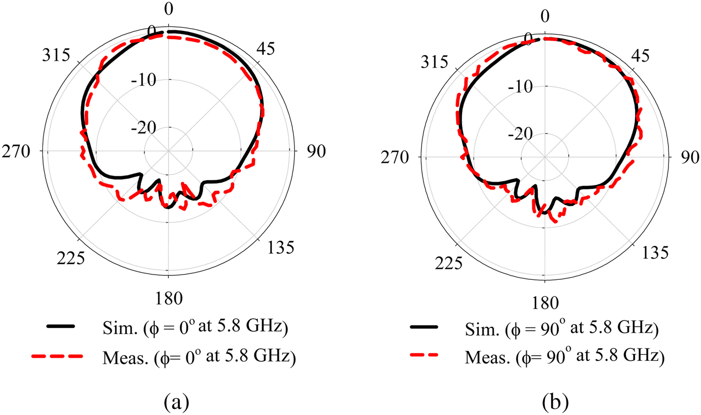
Fig. 11. Antenna co-polarized radiation patterns at H-plane (ϕ = 0o) and E-plane (ϕ = 90o) at 5.8 GHz on pork tissues.
Table 3. A comparative study for simulation and measurement results

NV, not verified
The performance of the proposed antenna with three metalized via holes has been compared with previously reported works and summarized in Table 4. The proposed antenna is highly compact than other listed prototypes [Reference Hong, Tak and Choi10]–[Reference Chen and Ku21]. The prototype reported in [Reference Chaturvedi and Raghavan15] and proposed structure are both realized by using QMSIW technology on same substrate and thickness. However, compared with the prototype in [Reference Chaturvedi and Raghavan15], the size of the proposed structure (Prototype-3) is miniaturized by 86.5% for the same operating frequency with a slightly lower gain and bandwidth. In addition, the proposed structure is more flexible to tune for different operating frequencies by loading a number of metalized vias while the radiation characteristics remain same.
Table 4. Comparison of proposed antenna parameters with previous refereed journals

In spite of compact size, the proposed antenna shows moderate gain and bandwidth with good radiation characteristics, which are comparable to the other listed prototypes. In addition, the proposed antenna is simple in design, as well as single-layered configuration which makes it easy for fabrication. The proposed antenna offers unidirectional radiation pattern and good radiation characteristics in proximity of pork tissues which makes it an optimum option for off-body communication.
Conclusion
In this work, simple circular QMSIW cavity-based antennas are presented and miniaturization is achieved up to 1/4th of FMSIW cavities by deploying quarter-mode topology. The operating frequency can be varied in the bands of interest (at 5.2/5.5/5.8 GHz) by inserting the metalized via holes subsequently in the top plane of the QMSIW cavity. At 5.8 GHz, the measured impedance bandwidth and a peak gain of the antenna in free space are 210 MHz and 4.8 dBi while in the proximity of pork tissues are 250 MHz and 3.25 dBi, respectively. The measured results closely follow the simulated results in free space as well as in proximity to the pork tissues in terms of both reflection coefficients and radiation patterns. The proposed antenna is a highly compact and single-layered structure. Moreover, it shows robust performance in an on-body condition which makes it an optimal candidate for compact hand-held devices.
 Divya Chaturvedi was born in Kanpur, India. She received her B. Tech. degree in Electronics and Communication Engineering from Uttar Pradesh Technical University, India and the M. Tech. degree in Electronics Engineering from Pondicherry Central University, India. She is working currently toward Ph.D. degree in the area of Substrate-Integrated Waveguide Antenna for Medical Applications at National Institute of Technology, Tiruchirappalli. Her area of research involves substrate-integrated waveguide, microwave-integrated circuits, metamaterial and biological effects of radiation on human body.
 Arvind Kumar was born in Jodhpur, India, in 1989. He received the UG degree in Electronics and Communication Engineering from Govt. Engineering College, Ajmer (India) in 2012, and the Master's degree in Electronics Engineering from Pondicherry Central University, India in 2015. He is working toward his PhD degree in the area of “Substrate-Integrated Waveguide Technology” under the guidance of Prof. S. Raghavan in the Department of Electronics and Communication Engineering, National Institute of Technology, Tiruchirappalli, India. His research interests include SIW-based antennas, circularly polarized antennas, and antenna arrays.
 S. Raghavan has 34 years of experience in teaching and research at the National Institute of Technology, Tiruchirappalli, India as a Senior Professor. He received his UG degree in ECE from College of Engineering, Guindy, PG degree in the Specialization of Microwave Engineering from College of Engineering, Trivandrum. He completed his Doctoral program in the field of Microwave-Integrated Circuits from I.I.T. Delhi, India under the guidance of Prof. Bharathi Bhat and Prof. S. K. Koul. He is a Senior Member of IEEE in MTT and EMBS, Life Fellow in BES, Fellow in IETE and IE, Life member in ISSS, MRSI, ISTE, EMC/EMI, IELTS, and ILA. His research interest includes microwave/millimeter-wave circuits and devices, microwave-integrated circuits, antennas, EMI/EMC, computational electromagnetics, RF/BIO MEMS, metamaterials and microwaves in biomedical applications. He has contributed more than 50 papers in international and national journals and 150 papers in international conferences including IEEE Explore proceedings.


