


I. INTRODUCTION
Oscillator is one of the important signal sources. At present, there has been increasing demand on oscillators with low-phase noise, because it determines the overall performance of radar and communication systems [Reference Jimenez-Martin, Gonzalez-Posadas, Parra-Cerrada and Segovia-Vargas1]. Besides, other factors of oscillators such as output power, harmonic suppression, DC–RF conversion efficiency and physical dimension, also play an important role.
Split-ring resonator (SRR) structure is one of metamaterial resonant structures, which is proposed theoretically by Pendry et al. [Reference Pendry, Holden, Robbins and Stewart2] and demonstrated experimentally by Smith et al. [Reference Smith, Padilla, Vier, Nemat-Nasser and Schultz3]. The equivalent-circuit models for the SRR structure, as well as its excitation through the planar transmission line, have been studied in detail in the previous work [Reference Baena, Bonache, Martin, Sillero, Falcone and Lopetegi4]. Some research work on the SRR with compact size and high Q-factor can be found in the literatures [Reference Montero-de-Paz, Ugarte-Munoz and Hettaiz-Martinez5–Reference Kim, Jo, Jang and Kim9]. However, the size of conventional SRRs is somewhat large in low-frequency range, which cannot meet the requirement of miniaturization. Thus, various modified SRR structures such as nested split-ring resonator (NSRR) have been proposed for performance improvement and size reduction. Compared with conventional SRRs, the size of the NSRR can be reduced. Meanwhile, its resonant characteristic is almost unchanged due to its geometric characteristics [Reference Melik, Unal, Perkgoz, Santoni, Kamstock, Puttlitz and Demir10]. The equivalent-circuit models for the NSRR structure have been set up, and the authors also have first put the NSRRs into a compact filter application [Reference Liu, Tang, Zhang and Huang11]. However, the application of this novel structure to the performance improvement of an active microwave component is rarely seen in literatures as the authors know.
In this paper, a novel miniaturized oscillator incorporating the NSRRs is presented. The proposed oscillator is featured by some advantages such as low-phase noise, good harmonic suppression and compact size, owing to the NSRRs with inherent high Q-factor and wide spurious-free characteristic. The fully planar and compact characteristics of the NSRR structure also exhibit its application potentiality to monolithic microwave integrated circuit (MMIC) technology.
II. DESIGN OF THE HIGH-Q NSRR STRUCTURE
The schematics of the conventional SRR and the proposed NSRR structures are shown in Fig. 1. In the NSRR structure, multiple SRRs are incorporated in the compact nested structure. They share the communal sides, excepting those where the gaps are located. The bottom line of the structure is connected, and it confers continuity in the nested design [Reference Liu, Tang, Zhang and Huang11]. Similar to the conventional SRR structure, the NSRR structure is also approximated by a LC resonator with a resonance frequency
 $f_0 = (2\pi \sqrt {LC} )^{ - 1} $
, where the inductance results from the current path on the NSRR structure and the capacitance depends on the gap dimensions of the NSRR structure [Reference Baena, Bonache, Martin, Sillero, Falcone and Lopetegi4]. Therefore, f
0 of the NSRR structure can be adjusted by changing the capacitance, inductance or both.
$f_0 = (2\pi \sqrt {LC} )^{ - 1} $
, where the inductance results from the current path on the NSRR structure and the capacitance depends on the gap dimensions of the NSRR structure [Reference Baena, Bonache, Martin, Sillero, Falcone and Lopetegi4]. Therefore, f
0 of the NSRR structure can be adjusted by changing the capacitance, inductance or both.
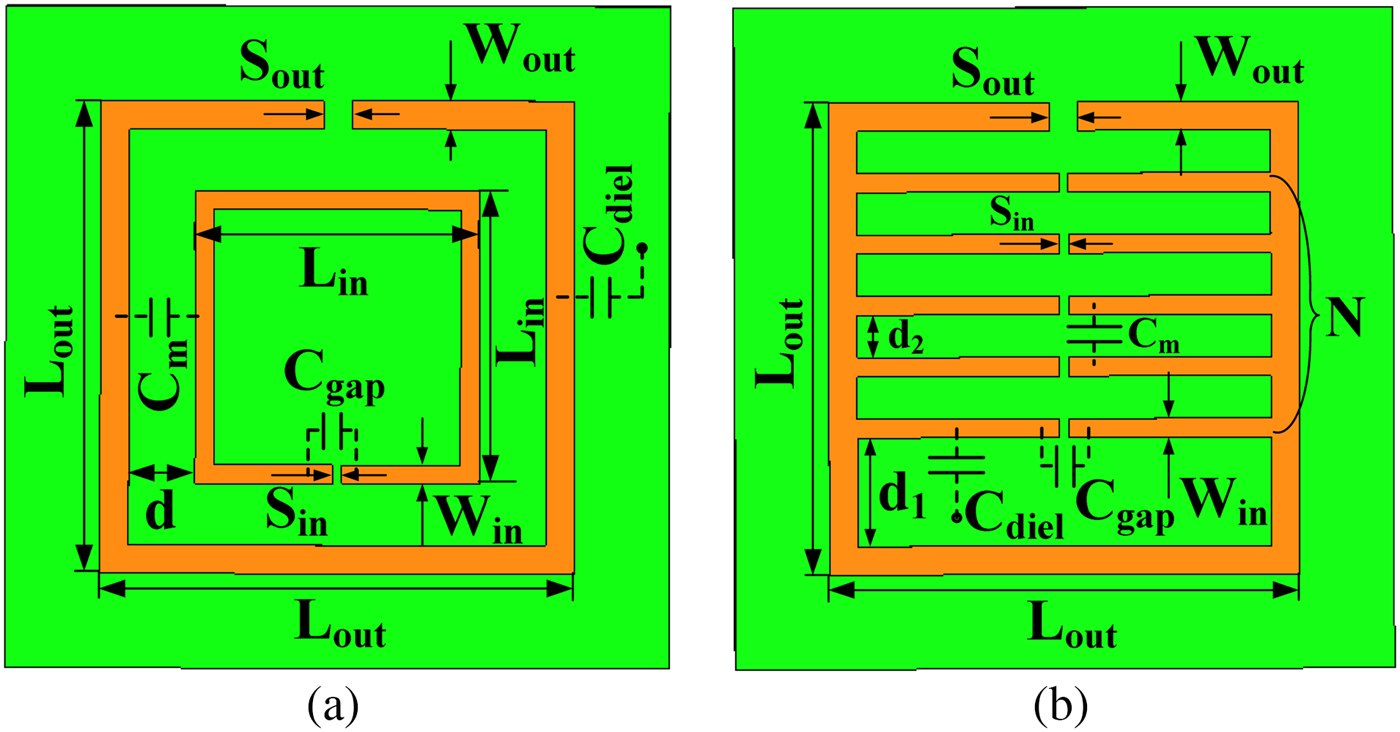
Fig. 1. Schematic representation of SRR structures. (a) Conventional SRR. (b) Proposed NSRR.
Compared with the conventional planar resonator structures, the NSRR structure exhibits a unique resonance mechanism owing to the distributed capacitance between the more concentric rings and the overall inductance of the ring. It behaves as a resonant tank, which can be excited by a time-varying magnetic field applied parallel to the rings’ axis. The proposed NSRR structure is able to obtain more available split gaps, so that the capacitance can be increased, and accordingly the resonance frequency can be adjusted. Therefore, it allows more compact resonator application. Additionally, due to its abrupt sign change of permittivity and the resultant abrupt change of the wave propagation direction in the resonator application frequency range, the NSRR structure has a Q-factor higher than those of other conventional planar resonators. The influence of physical dimension on the resonance frequency and Q-factor of the NSRR has been studied in detail in the authors’ previous work [Reference Liu, Tang, Zhang and Huang11], which dramatically depends on the numbers of the nested split gap N due to the realization of a larger C gap in a compact area. Besides, to obtain the sufficient C diel that serves as the distributed capacitance, a dielectric substrate with high relative permittivity is also an important factor. In this paper, the Taconic CER-10 substrate with a relative permittivity of 9.5 and a thickness of 0.635 mm is used.
Furthermore, the proposed NSRR structure also has some excellent features of the stepped impedance resonator structure due to the separate parameters W out and W in . The corresponding spurious frequency response can be adjusted by changing the impedance ratio of the nested combs and the outer coil, as shown in the previous work [Reference Liu, Tang, Zhang and Huang11].
Since the single microstrip line structure cannot provide high Q-factor performance, the NSRRs are incorporated with the microstrip line to achieve a very sharp band rejection. As shown in Fig. 2, the single NSRR and one pair of the NSRRs are designed and fabricated to be coupled to a terminated short-circuited microstrip line, respectively. The NSRR structure is designed based on the desired resonance frequency, and it is located beside the one side and both sides of the center terminated short-circuited microstrip line, respectively. In addition, the distance S between the NSRRs and microstrip line and the length L of the terminated short-circuited microstrip line are optimized for a higher Q-factor and a better band rejection.
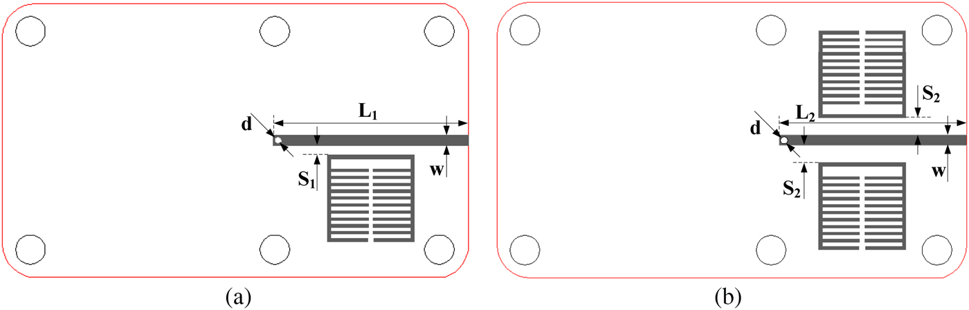
Fig. 2. Layout of the NSRRs incorporated with terminated short-circuited microstrip line. (a) Single NSRR. (b) One pair of the NSRRs.
The size of each NSRR unit cell is 5 × 5 mm2, i.e. only 0.12λ g × 0.12λ g , where λ g is the guided wavelength of resonance frequency. Some important dimension parameters are: S 1 = 0.55, S 2 = 0.98, L 1 = 11.3 and L 2 = 10.75 mm, respectively. They are adjusted for better band rejection and further miniaturization.
Figure 3 shows the simulated results of the proposed NSRRs incorporated with terminated short-circuited microstrip line. Both the single NSRR and one pair of the NSRRs operate near 2.4 GHz. The Q-factor is calculated by f 0/BW, where f 0 is the center frequency and BW is the 3-dB bandwidth [Reference Kajfez and Wheless12]. The Q-factor of 183 and 202 are obtained near 2.4 GHz for the single NSRR and one pair of the NSRRs, respectively. In Table 1, the performance of the proposed NSRRs and other planar resonators is compared.

Fig. 3. Simulated results of the NSRRs incorporated with terminated short-circuited microstrip line.
Table 1. Performance comparison between various planar resonators

Figure 4 shows the photographs and measured results of the fabricated single NSRR and one pair of the NSRRs. They are measured by an Agilent N5230A PNA-L network analyzer, and both of the measured resonance frequencies are approximately 20 MHz lower than the corresponding simulated results. The pass-band and corresponding S parameter characteristic of the resonators is applied to the oscillation frequency selection of the final reflection-type oscillator circuit. According to [Reference Hajimiri and Lee15], the phase noise of oscillator mainly depends upon the carrier power and the Q-factor of the resonator. Compared with that of conventional planar resonators, the higher Q-factor of proposed NSRR could lead to the phase-noise reduction of the oscillator circuit. In addition, the simulated and measured results also show that one pair of the NSRRs could bring in the higher Q-factor of the resultant resonator component than the single NSRR unit cell does.

Fig. 4. Photograph and measured results of the fabricated NSRRs incorporated with terminated short-circuited microstrip line. (a) Photograph of the single NSRR. (b) Photograph of one pair of the NSRRs. (c) Measured results of the single NSRR. (d) Measured results of one pair of the NSRRs.
In addition, the spurious resonances, which are obviously observed in most conventional quarter- or half-wavelength resonators, are not observed in this novel NSRR within wide frequency range, as shown in Fig. 4. It is due to the aforementioned unique resonance mechanism of the structure. The spurious resonance of the single NSRR is slightly observed in 2.7 times the center frequency, while the spurious-free band of the one pair of the NSRRs is more than four times the center frequency. This wide spurious-free band characteristic of the NSRR structure can lead to superior harmonic suppression characteristic of the resultant oscillator circuit.
III. DESIGN AND MEASUREMENT OF OSCILLATORS USING NSRRS
In this paper, two novel planar oscillators using the single and one pair of the NSRRs are designed, and the layouts are shown in Fig. 5, respectively. The negative resistance is generated from a transistor (Mitsubishi Semiconductor MGF4916 G HEMT) with a shunt stub added to its source terminal. In the vicinity of 2.4 GHz, the small signal oscillation conditions are satisfied by tuning the output matching stubs of the circuit. The proposed NSRR cells are added to its gate terminal as a fundamental frequency selection and harmonic tuning component of the oscillator circuit. HFSS and ADS simulation tools are used to design and optimize the oscillator circuits. Two final circuits are fabricated on the Taconic CER-10 substrate (ε r = 9.5) with a thickness of 0.635 mm, and the circuits size is only 46 × 49 mm2, as shown in Fig. 6.

Fig. 5. Layout of the proposed compact low-phase noise planar oscillators using the NSRRs. (a) Single NSRR. (b) One pair of the NSRRs.

Fig. 6. Photograph of the fabricated compact low-phase noise planar oscillators using the NSRRs. (a) Single NSRR. (b) One pair of the NSRRs.
Figures 7 and 8 show the output spectrum of the two fabricated oscillators measured by an Agilent E4440A spectrum analyzer. The single NSRR oscillator exhibits the stable oscillation at 2.41 GHz with 11.64 dBm output power, which is near the resonance frequency and the design frequency. The phase noise and second harmonics suppression are measured as −105.37 dBc/Hz@100 kHz, −131 dBc/Hz@1 MHz, and −40 dBc at the bias condition of V DS = 5 V and I DS = 10 mA.

Fig. 7. Measured results of the proposed single NSRR oscillator. (a) Output power. (b) Second harmonic suppression. (c) Phase noise at 100 kHz offset. (d) Phase noise at 1 MHz offset.

Fig. 8. Measured results of the proposed oscillator with one pair of the NSRRs. (a) Output power. (b) Second harmonic suppression. (c) Phase noise at 100 kHz offset. (d) Phase noise at 1 MHz offset.
At the same bias condition, the proposed oscillator with one pair of the NSRRs exhibits the stable oscillation at 2.43 GHz with 11.78 dBm output power. The phase noise and second harmonics suppression are measured as −110 dBc/Hz@100 kHz, −132.4 dBc/Hz@1 MHz, and −45.49 dBc. In addition, the DC–RF conversion efficiency of these two oscillators is calculated as 30%.
Compared with the oscillator using single NSRR, the measured results of the oscillator with one pair of the NSRRs exhibit the improvement of 4.6 dB in the phase noise at 100 kHz offset and 5.5 dB in the second harmonics suppression. The improvement is due to the increase of the Q-factor and spurious-free resonance characteristic of resonator structure, as shown in Fig. 4. Compared with the performance of state-of-the-art oscillators operating around 2.4 GHz, as shown in Table 2, the proposed NSRR structure is very effective in improving the performance of the conventional oscillators and simultaneously helps to reduce their size. The combination of the novel NSRR structure and planar oscillator techniques can be applied to design miniaturized high-performance hybrid microwave integrated circuit (HMIC) or MMIC oscillators.
Table 2. Performance comparison between state-of-the-art oscillators.

IV. CONCLUSIONS
In this paper, a novel oscillator utilizing the NSRRs is presented. The phase noise and harmonic suppression performances of the oscillator are improved due to the inherent high Q-factor and wide spurious-free band characteristics of the NSRR structure. Owing to the unique resonance mechanism, the NSRR unit cell is only 0.12λ g × 0.12λ g and the fabricated oscillator is fully planar and very compact. The output power is 11.78 dBm and the second harmonic suppression is −45.49 dBc. The measured phase noise is −110 dBc/Hz@100 kHz and −132.43 dBc/Hz@1 MHz offset from 2.43 GHz carrier frequency. The DC–RF conversion efficiency is 30%. The measured results reveal that the novel NSRR can realize the compact low-phase noise planar oscillator, and it also shows the potentiality of the NSRR as a promising novel structure in the future microwave circuit design. The combination of the novel NSRR structure and planar oscillator techniques can be applied to design miniaturized high-performance HMIC or MMIC oscillators.
ACKNOWLEDGEMENT
The authors would like to thank Editors and Reviewers for their work and help.
 Yong Liu received his B.S. and Ph.D. degrees in Electromagnetism and Microwave Technology in UESTC. Now he is a Research Associate in UESTC. He has authored more than 15 journal and conference papers. His research interests include microwave and millimeter-wave communication, circuit system design, etc.
 Neng Xie received his master degree from the University of Electronic Science and Technology of China (UESTC).
 Xiaohong Tang received his B.S. and Ph.D. degrees in Electromagnetism and Microwave Technology from the University of Electronic Science and Technology of China (UESTC). Now he is a Professor in UESTC. He has authored more than 100 journal and conference papers. He was also the recipient of several national and provincial awards. His research interests include microwave and millimetre-wave communication, computational electromagnetics, etc.
 Fei Xiao received his B.S. degree in Applied Physics from ChongQing University in 1997, the M.S. degree in Physical Electron and Ph.D. degree in Radio Physics from the University of Electronic Science and Technology of China (UESTC) in 2002 and 2005, respectively. From 2009 to 2010, he was a visiting researcher to Royal Institute of Technology, Sweden. Now, he is currently an Associate Professor in UESTC. Up to now, he has authored more than 60 journal and conference papers. His research interests include filter synthesis, microwave passive components design, computational electromagnetics, etc.


