


Introduction
Microwave power transmission (MPT) technology [Reference Brown1] has attracted more and more attention because of its advantages of low transmission loss, easy control of the beam intensity and the direction. A rectenna converts the received electromagnetic wave into direct current (DC) energy for energy supply, which is the key component of a MPT system. With the development of integrated circuit technology and semiconductor technology, MPT technology has been widely used in low-power electronic devices, such as radio frequency identification [Reference Boaventura and Carvalho2], wireless sensor networks [Reference Huang and Lau3], and energy collection [Reference Bolos, Blanco, Collado and Georgiadis4]. If the high microwave to DC conversion efficiency rectenna has a low profile and a compact size, it can adhere to the surface of the electronic devices or airships as a wireless battery.
Three kinds of printed transmission lines have been used to design the rectennas, the microstrip line [Reference Harouni, Cirio, Osman, Gharsallah and Picon5, Reference Yang, Jun, Lu, Yilin, Bing, Huacheng and Kama6], coplanar waveguide (CPW) [Reference Nie, Yang, Tan and Han7, Reference Chiou and Chen8], and coplanar stripline (CPS) [Reference Suh and Chang9, Reference Ren and Chang10]. The microstrip rectenna has a low profile but the rectifying circuit needs ground via for connecting the active components and the gain of the patch antennas is about 5 dBi. Traditionally, the gain of the CPW and CPS antennas is about 6 dBi and Reference [Reference Strassner and Chang11] improves the gain to 10.7 dBi by setting a reflecting plane at 0.21λ 0 away behind the CPS antenna. Therefore, the CPW and CPS rectennas need a metal reflector to improve the gain, which results in a high profile and bulky size. A circularly polarized (CP) antenna can receive any linearly polarized electromagnetic wave and the CP one with the same rotation direction, which lessens the requirement of polarization alignment [Reference Yang, Lu, Jun, Yilin, Bing, Huacheng and Kama12].
The artificial magnetic conductor (AMC) structure was proposed by Sievenpiper in 1999 [Reference Sievenpiper, Zhang, Broas, Alexopolous and Yablonovitch13]. Studies have shown that the AMC surface will produce in-phase reflection when the reflection phase is in the range of −90°~90°. Reference [Reference Feng, Zhai, Xi, Yang, Zhang and Yang14] designed a CP cross dipole antenna with AMC reflector. The height of the antenna was reduced to 0.12 λ 0 but the gain was only 6 dBi.
In this paper, a high-efficiency CP rectenna with low profile and compact size is designed based on AMC structure. The circular polarization operation is realized by a CPS-fed dual rhombic loop antenna with an AMC reflector, which makes the antenna have high gain, low profile, and harmonic suppression function. The compact and thin CP rectenna with high conversion efficiency could be printed on the surface of electronic devices and applied as the wireless battery or loaded on the airship for far-distance MPT.
Circular polarized receiving antenna
CP antenna design
The newly proposed CP antenna is shown in Fig. 1. The antenna is stacked by three substrate layers as shown in Fig. 1(a). The CPS-fed dual rhombic loop is printed on the top side of the upper layer, which is plotted in Fig. 1(b). The middle layer is the air and the lower one is the AMC reflector as shown in Fig. 1(c). The thicknesses of the three layers are h 1, h 2, and h 3, respectively. All design models are implemented with the full-wave electromagnetic software High Frequency Structure Simulator (HFSS). The substrate is F4B-2 with the relative permittivity of 2.65 and the dielectric loss tangent of 0.001.

Fig. 1. Configuration of the proposed antenna. (a) Side view, (b) top view of a dual rhombic loop, (c) top view of the AMC reflector.
The operation frequency of the CP dual rhombic loop is decided by the side length of L. The perimeter 4 × L of the dual rhombic loop is about 1.2 λ 0 at the center frequency of 5.8 GHz. Figure 2 shows the simulated reflection coefficients for different lengths of L. As L decreases, the resonance frequency increases gradually. Two gaps with the size of s 1 on the dual rhombic loop set symmetrically with respect to the center of the structure are used to excite the CP wave. The distance from the gap to the vertex of dual rhombic loop is d 1. The position d 1 and the width s 1 determine the axial ratio (AR). Figure 3(a) shows the influence of distance d 1 on the AR when s 1 is fixed. When d 1 gets bigger or smaller than 11.5 mm, AR would be worse. Similarly, Fig. 3(b) shows the influence of width s 1 on the AR when d 1 is fixed. When s 1 gets bigger or smaller than 1.6 mm, AR would be worse. Hence, the lowest AR of 1.3 dB is obtained when d 1 = 11.5 mm and s 1 = 1.6 mm. The tuning stub L 1 is used to match the input impedance because it determines the reactance of the input impedance. Figure 4 shows the reactance of different stub length L 1. We can find that the reactance tends to zero at 5.8 GHz, when L 1 = 16.5 mm. The optimized CP antenna parameters were as follows: h 1 = 0.8 mm, h 2 = 3 mm, h 3 = 1.5 mm, L = 15.5 mm, L 1 = 16.5 mm, s 1 = 1.6 mm, d 1 = 11.5 mm. So the total thickness of the rectenna is 5.3 mm.

Fig. 2. Simulated |S11| of the receiving antenna versus the frequency with different sizes of L.

Fig. 3. Simulated AR of the receiving antenna versus the frequency. (a) with different sizes of d 1 (b) with different sizes of s 1.

Fig. 4. Reactance of the receiving antenna's input impedance versus the frequency with different lengths of tuning stub L 1.
Table 1 shows the comparison of the rectenna profiles between our work and recent publications. It can be seen that the thickness of the air layer of the published rectennas were about λ 0/4, which results in high profiles. The proposed rectenna with AMC has a thin air layer that yields lower profile.
Table 1. Comparison of different rectenna profiles

The AMC is acted as a reflection plate with low profile to improve the antenna gain. The AMC reflector has a sandwich structure, whose top and bottom are the metal patch and the ground, respectively, while the middle is the substrate. The periodic units on the top surface are shown in Fig. 1(c), which is a 5 × 3 square patch. The length of the unit metal patch is a, and the gap is d. According to the operation mechanism of the AMC surface, the resonance frequency of AMC surface corresponds to the 0° of the reflection coefficient phase and the operation bandwidth is defined by the phase between −90° and 90° [Reference Prakash, Abegaonkar, Basu and Koul16]. Therefore, the unit cell of the AMC surface is designed to show 0° reflection phase at 5.8 GHz. Figure 5 shows the simulated reflection phase responses of different AMC unit cell configuration parameters. It could be seen that the increase in patch size (a) results in decrease of resonance frequency. With the gap d increasing, the resonance frequency increases. In short, the resonance frequency and operating band of the AMC unit cell can be basically controlled by the physical parameters of a and d. After optimization, the reflection phases of 5.8 GHz are close to 0° when a = 11 mm, d = 1.5 mm.

Fig. 5. Simulated reflection phases of AMC unit cells versus the frequency with different AMC cell configuration parameters.
The rectifying diode in the rectenna is a nonlinear element, which would excite high order harmonics. The re-radiation of the high order harmonics by the antenna would decrease the rectifying efficiency. Generally, it is necessary to insert a low pass or band pass filter between the antenna and the rectifying circuit to suppress the high order harmonics [Reference Strassner and Chang11]. However, it will increase the rectenna size and lower the conversion efficiency due to the insert loss. In this design, the AMC reflector makes the antenna have a harmonic suppression function. Figure 6 shows the simulated reflection coefficient of the antenna versus the frequency. It can be seen that the reflection coefficient on the second and third harmonics are −2.1 and −0.6 dB, respectively. Thus, the low pass filter between the rectifying circuit and the antenna could be omitted and the rectenna structure is more compact.

Fig. 6. Simulated |S11| of the antenna.
Measurement
In order to test the antenna performances, it is necessary to design a balun [Reference Tu and Chang17]. The balun consists of a multi-section impedance transformer and a quarter-wavelength fan-shaped microstrip stub, which is plotted in Fig. 7. Balun's irregular ground is within the dot line range. Parameters of the balun are as follows: W 1 = 7 mm, W 2 = 14.7 mm, W 3 = 10.2 mm, B r = 5 mm, B d = 80°, R 1 = 7.7 mm, W 4 = 0.6 mm, R 2 = 7 mm, W 5 = 2.14 mm.

Fig. 7. The structure of the receiving antenna with balun.
The measured and simulated reflection coefficient and AR of the proposed antenna with balun are shown in Figs 8 and 9, respectively. For comparison, the simulated one without balun was also plotted. The CP performances were measured using a rotating linearly polarized transmitting horn antenna. From Fig. 8, the simulated impedance bandwidth without balun of |S11|<−10 dB is 23.6% (5.43–6.8 GHz) and the simulated one with balun is 23.6% (5.43–6.8 GHz). The impedance bandwidth is in agreement and also reveals good performance of the balun. The simulated impedance bandwidth with balun of |S11|<−10 dB is 23.6% (5.43–6.8 GHz), while the measured one is 25.3% (5.55–7.02 GHz). A little distinction may be caused by the inaccuracy of the fabrication and the measurement system. From Fig. 9, the simulated 3-dB AR bandwidth without balun is 5% (5.68–5.97 GHz) and the simulated one with balun is 5.2% (5.6–5.9 GHz). It can be seen that the balun affects the AR because the balun is on the same plane with the antenna and produces radiation to change the CP characteristic. The simulated 3-dB AR bandwidth is 5.2% (5.6–5.9 GHz) and the measured one is also 5.2% (5.7–6 GHz). The simulated is relatively consistent with the measured results. But the frequency shift may be caused by the error of the fabrication and weld.

Fig. 8. Simulated and measured |S11| of the receiving antenna.

Fig. 9. Simulated and measured AR of the receiving antenna.
The simulated and measured gains against frequency are given in Fig. 10. The simulated gain is 10.3 dBi at 5.8 GHz, while the measured one is 9.8 dBi. This discrepancy may be caused by the balun's loss. It should be noticed that the balun is not necessary in the practical applications. The simulated and measured normalized radiation patterns in the two principal planes (xoz and yoz plane) at 5.8 GHz are plotted in Fig. 11. The pattern was also measured using a rotating linearly polarized transmitting horn antenna. The transmitting antenna is a spinning horn with linear polarization operation, where the calibration factor GF is added to the measured gain
 $$GF = 20\log \left[ {\displaystyle{{({10}^{AR/20} + 1)} \over {\left( {\sqrt 2 \cdot {10}^{AR/20}} \right)}}} \right]\;({\rm dB}),$$
with the unit of AR in decibels. In this way, the CP performance of the antenna can be obtained. The ripples in the pattern represent the quality of CP radiation. The depth of small dips in the measured pattern defines the AR. The ripples in the pattern represent the quality of CP radiation. We can find that the antenna has a better circular polarization in the direction of its maximum beam. The manufacture precision and the welding of the SMA connector influence the deviation between the simulation and the measure results.

Fig. 10. Simulated and measured gains of the proposed antenna.
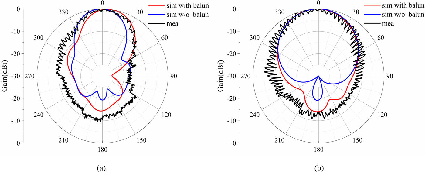
Fig. 11. Simulated and measured normalized radiation pattern at 5.8 GHz of the proposed antenna (a) xoz plane (b) yoz plane.
Rectifying circuit
Rectifying circuit design
The rectifying circuit consists of a rectifying diode, a capacitor, and a resistive load, as shown in Fig. 12. The Schottky diode of MA4E1317 is adopted as the rectifying diode, which has fast switching response and high cutoff frequency. The CPS transmission line avoids the use of ground via. It is easy for diodes and capacitors to be connected in shunt and series.

Fig. 12. Configuration of the proposed rectifying circuit.
In order to integrate the receiving antenna with rectifying circuit, the input impedance of the two parts needs to be matched first. The input impedance match network is realized by the CPS transformer with the length of L 1, the width of W t and the gap of g t. By optimizing the size of L 1, W t, and g t, the good impendence matching is achieved. Generally, the closed formula in Reference [Reference Yoo and Chang18] or software Advanced Design System (ADS) have been used to calculate the input impedance of the rectifying circuit. However, the closed formula is limited because it has been derived under some ideal conditions. The ADS does not have CPS model. Hence, in the design process, the ideal transmission line is used to replace the CPS for simulation in ADS. At the first stage, the characteristic impedance and electric sizes of the ideal transmission line were optimized with the goal of good matching performance and high rectifying efficiency. After optimization, the line width W t, the gap width g t, and the length of L 1 were obtained by the characteristic impedance and electric sizes of the ideal transmission line.
From Fig. 12, the DC-pass filter consists of the capacitor and the CPS section with the length of L 2, which is the distance between the diode and the capacitors. The length of L 2 is 1/4 wavelength at the fundamental wave. The DC-pass filter allows even harmonics to flow while odd harmonics are reflected. The even harmonics does not cause power loss because it does not have any voltage drop. The odd harmonics is reflected back to the diode for rectifying again [Reference Gutmann and Borrego19]. So the DC-pass filter can suppress high order harmonics.
Measurement
The rectifying circuit is simulated and optimized by ADS. Based on the geometric parameters of the simulation, the rectifying circuit was fabricated. In order to test the circuit performance, it is also necessary to design the balun. The balun structure is the same asFig. 7 with different sizes. Geometrical parameters are as follows: W 1 = 7 mm, W 2 = 47 mm, W 3 = 9.2 mm, B r = 4 mm, B d = 80°. The rectifying circuit with balun has been connected to the signal generator through a 50 Ω SMA connector for testing. The simulated and measured rectifying efficiencies of rectifying circuit versus the input power and the load are shown in Figs 13 and 14, respectively. A peak efficiency of 77% is measured at 102.3 mW input power. From Fig. 14, the maximum rectifying efficiency of the simulated and measured could be obtained when the load is 240 Ω. Compared with the simulated results, about 7% fluctuation has been observed, which was probably induced by the manual welding process of the diode and capacitor. The simulated and measured curves are basically consistent, which proves the validity of using an ideal transmission line to design CPS rectifying circuit.

Fig. 13. Simulated and measured efficiency versus the input power of rectifying circuit at 5.8 GHz.

Fig. 14. Simulated and measured efficiency versus the load of rectifying circuit at 5.8 GHz.
Rectenna measurement
The CPS feed line of the antenna and the input port of the rectifying circuit has the same characteristics impedance, so they could be integrated directly. Figure 15 illustrates the front view of the fabricated rentenna. The overall dimension of the proposed rectenna is 66 mm × 60 mm × 5.3 mm. According to Fig. 15, the air layer of the rectenna is filled with Polymethacrylimide (PMI) foam which has the same dielectric constant as air. Then it is fixed by nylon screw. So the thickness of the air layer can be adjusted by PMI foam. The proposed rectenna has good mechanical robustness related to the air layer. The conversion efficiency of the CP rectenna is measured in an anechoic chamber. The measurement system is illustrated in Fig. 16. A standard horn was used as the transmitting antenna. Firstly, the proposed CP antenna with balun was placed in a fixed position, and its received power P r was measured through a power meter. Secondly, the antenna was replaced by the rectenna in the same position. By measuring the voltage across the resistor, the conversion efficiency can be obtained by
 $$\eta = \displaystyle{{P_{out}} \over {P_r}} = \displaystyle{{V_d^2} \over {R_L\cdot P_r}},$$
where V d is the voltage on the resistor, R L is the resistance value. By this means, the use of Friis transmission equation can be avoided and precisely find out the received power of the rectenna. The distance between the transmitting horn antenna and the receiver is 50 cm. The transmitting horn antenna is a linearly polarized horn antenna with a gain of 16.55 dBi and a size of 13.5 cm × 10 cm. This distance is the near field, so the rectenna will obtain a higher received power.

Fig. 15. Photograph of the fabricated rectenna.

Fig. 16. Rectenna measurement system.
Figure 17 shows the measured conversion efficiency of the rectenna versus the received power on different loads. It can be found that the peak conversion efficiency is 76% on the load of 240 Ω and received power of 117.5 mW. The optimum load value of the rectenna is the same as the rectifying circuit. To investigate the CP property of the proposed rectenna, the conversion efficiency on different azimuth angle φ were measured. The φ is the angle between the transmitting antenna and receiving antenna along polar axis. Figure 18 shows the conversion efficiency at 5.8 GHz versus the angle φ when the received power are 55, 83.2, and 117.5 mW. The maximum conversion efficiency is 76% when the angle is 0°. There is about 4% fluctuation in the conversion efficiency between different angles at 117.5 mW received power. Therefore, the rectenna has good circular polarization characteristics. When the load is 240 Ω,the conversion efficiency at 5.8 GHz versus the received power is shown in Fig. 19. From Fig. 19, the efficiency increases with the received power until the received power is 117.5 mW. When the received power is higher than 117.5 mW, the efficiency decreases sharply.
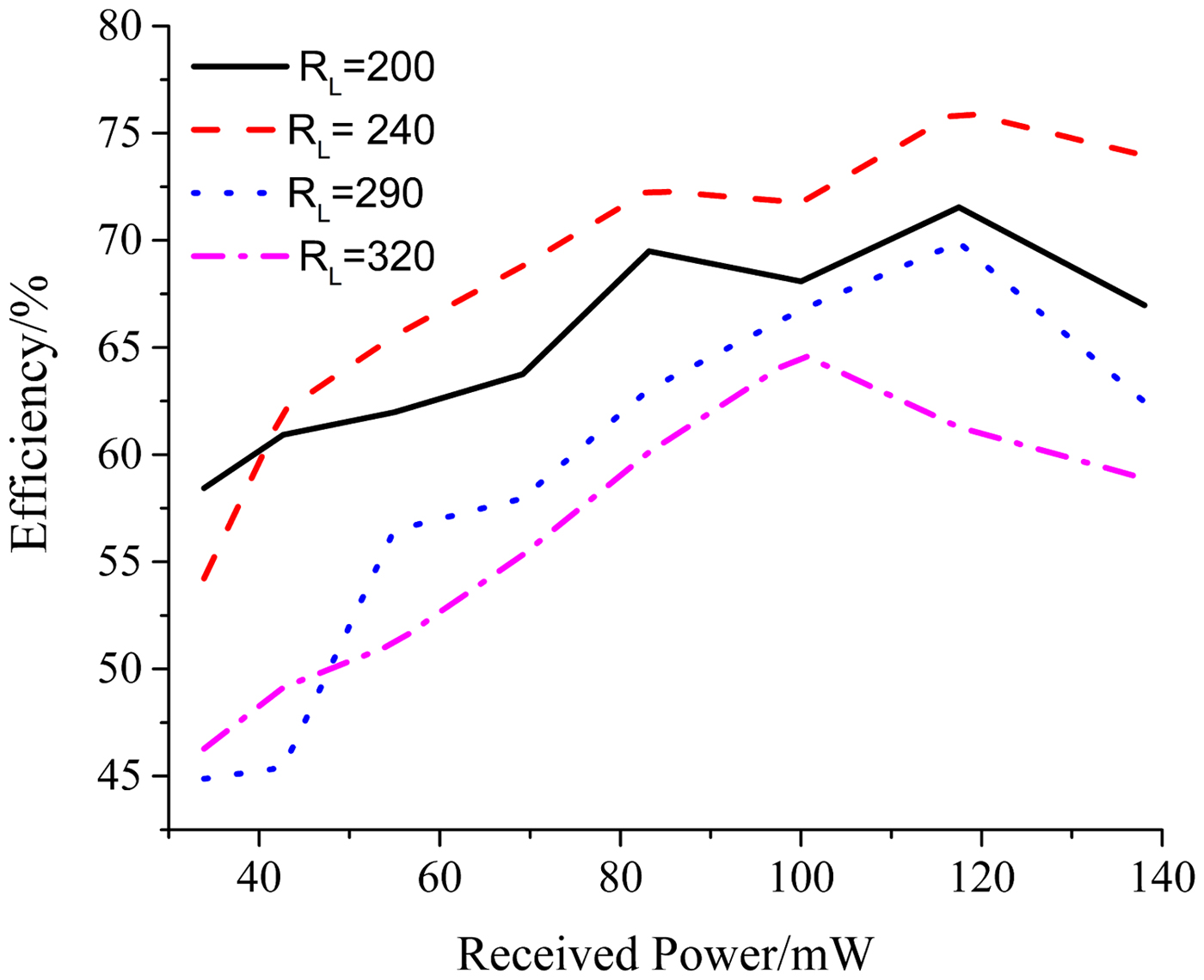
Fig. 17. Efficiency versus the input power under different load at 5.8 GHz.

Fig. 18. Efficiency versus the angle φ under different received power at 5.8 GHz.

Fig. 19. Measured efficiency versus the received power at 5.8 GHz.
Conclusion
In this paper, a high-efficiency CP rectenna with low profile has been proposed. A dual rhombic loop based on AMC antenna with the characteristics of high gain and low profile is designed as the CP receiving antenna. The AMC reflector makes the antenna have a harmonic suppression function so the low pass filter between the rectifying circuit and the antenna could be omitted and the rectenna has compact structure. The measured results show that the rectenna has a high conversion efficiency and good circular polarization characteristics. The maximum conversion efficiency at 5.8 GHz is 76%. When the linearly polarized transmitting antenna is rotated, the conversion efficiency of the rectenna is maintained at about 74%. The CP rectenna has the good features of high conversion efficiency and no requirement of polarization alignment. This compact structure, low profile, and CP operation of the rectenna can be applied as the wireless battery for some electronic devices or airships.
Acknowledgement
This work was supported by the Natural Science Foundation of China under Grant no. 61771300.
 Lin Li is currently pursuing the M.S. degree with the Shanghai University, Shanghai. His current research interests include rectenna and microwave power transmission.
 Xue-Xia Yang received the B.S. and M.S. degrees from Lanzhou University, Lanzhou, China, in 1991 and 1994, respectively, and the Ph.D. degree in electromagnetic field and microwave technology from Shanghai University, Shanghai, China, in 2001. From 1994 to 1998, she was a teaching assistant and a lecturer in Lanzhou University, China. From 2001 to 2008, she was a lecturer and an associate professor in Shanghai University, China. She is currently a professor and the Head of the Antennas and Microwave R&D Center at Shanghai University. She has authored or coauthored over 180 technical journal and conference papers. She is also a frequent reviewer for over 10 scientific journals. Her research interests include antennas theory and technology, computational electromagnetics and microwave power transmission. She is now a member of the Committee of Antenna Society of China Electronics Institute and Senior Member of China Electronics Institute. She is an associate editor for the Journal of Shanghai University (Science edition).
 Geliang Zhu is currently pursuing the M.S. degree with the Shanghai University, Shanghai. His current research interests include rectifying circuit and microwave power transmission.
 Qi Luo received the M.Sc. degree in data communications from The University of Sheffield, Sheffield, UK, in 2006, and the Ph.D. degree in electrical engineering from the University of Porto, Porto, Portugal, in 2012. From 2012 to 2013, he was a Research Fellow with the Surrey Space Center, Guildford, UK He is currently a Research Associate with the School of Engineering and Digital Arts, University of Kent, Canterbury, UK. His current research interests include smart antennas, circularly polarized antennas, reflectarray, multiband microstrip antennas, and electrically small antenna design. He has been serving as a reviewer for a number of technical journals and conferences. He is an Outstanding Reviewer for the IEEE TRANSACTIONS ON ANTENNAS AND PROPAGATION in 2015.
 Steven Gao is currently a Professor and the Chair of RF and microwave engineering with the University of Kent, UK. He has authored two books including the Space Antenna Handbook (Wiley, 2012) and the Circularly Polarized Antennas (IEEE Wiley, 2014), over 200 papers, and several patents. His research covers smart antennas, phased arrays, multi-in multi-out, satellite antennas, RF/microwave/mm-wave circuits, satellite communications, ultra-wideband radars, synthetic-aperture radars, and mobile communications. He is a Distinguished Lecturer of the IEEE AP-S, an Associate Editor of the IEEE TRANSACTIONS ON ANTENNAS AND PROPAGATION and the Radio Science, and the Editor-in-Chief of Wiley Book Series on Microwave and Wireless Technologies. He was the General Chair of LAPC 2013 and a Keynote Speaker or Invited Speaker at some international conferences, such as AES'2014 (China), IWAT'2014 (Sydney), SOMIRES'2013 (Japan), and APCAP'2014 (China).


