Introduction
Power dividers have been widely used in radar systems such as power combining amplifiers and antenna arrays [Reference Guo, Song, Zhou and Fan1–Reference Becker and Oudghiri12], and higher demands are placed on compact, low loss, and high isolation. In recent years, many kinds of multi-way power dividers, based on the waveguide, microstrip line or SIW, have been widely investigated. In [Reference Ruiz-Cruz, Fahmi and Mansour6, Reference Song and Xue7, Reference Becker and Oudghiri12], waveguide power dividers are investigated with low insertion loss. However, the isolation between output ports is not high and it is difficult to achieve miniaturization and integration within one wavelength. Meanwhile, in [Reference Yu, Tsai and Chang4, Reference Song, Mo, Xue and Fan9], the power dividers designed with a microstrip line and slotline show the potential of compact size and easy integration with active devices. In [Reference Chen, Che, Wang and Feng5, Reference Khan and Mandal8, Reference Dong-Sik, Jindo and Hai-Young10], power dividers based on the substrate integrated waveguide (SIW) are designed. Good isolation between the four output ports and good impedance matching at all the ports is achieved. However, the insertion losses caused by microstrip-to-SIW, microstrip-to-half mode substrate integrated waveguide (HMSIW) transitions, and the SMA connectors are large that cannot meet the demands of high power-combining efficiency.
The suspended stripline is widely used in filter design due to its low insertion loss [Reference Ruf and Menzel13, Reference Shan and Shen14]. In [Reference Dong-Sik, Jindo and Hai-Young10], suspended striplines are applied in the design of the power divider to reduce the insertion loss. However, it is cannot meet the demands for high isolation.
In this letter, a four-way suspended-stripline power divider at the X band with compact size and good input/output return loss is designed and fabricated. The suspended stripline is introduced to the designed power-divider network and connected to the SMA connectors with low insertion loss. The microstrip lines are introduced to obtain attractive high isolation without effect input return loss and insertion loss.
Structure, analysis, and design
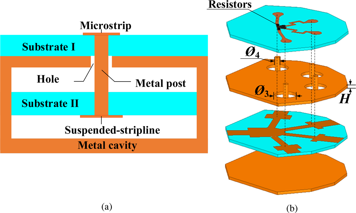
Figures 1 and 2 demonstrate the structure of the suspended-stripline power divider. The presented power divider includes the power-dividing circuit and the isolation network. The suspended stripline has been used in the power dividing circuit, while the microstrip line has been used in the isolation network. The power dividing network and isolation network are connected through vias, as shown in Fig. 1. Four isolation resistors are located on the microstrip isolation circuit with a common point, as shown in Fig. 2(b).

Fig. 1. Quasi-planar suspended-stripline power divider: (a) section structure view and (b) 3D structure view.
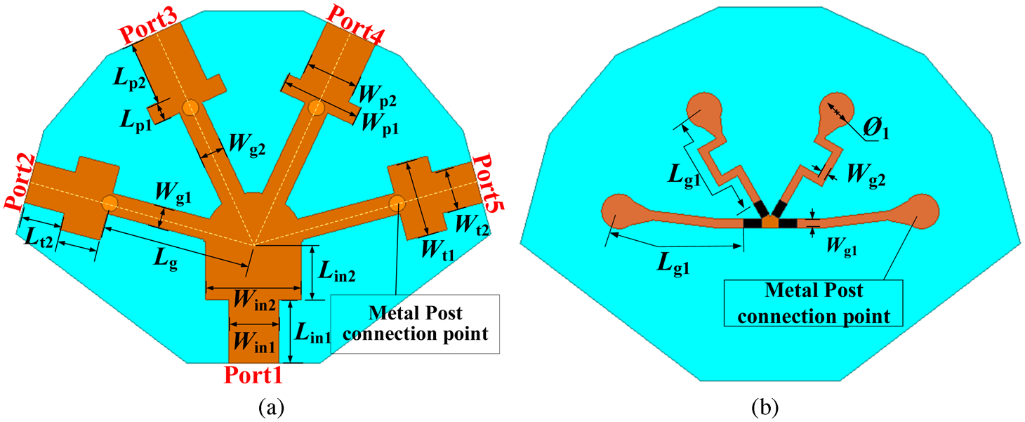
Fig. 2. (a) Suspended-stripline power divider network and (b) microstrip isolation network.
Since the power divider is almost symmetric, the even- and odd-mode equivalent circuit method can be applied to analyze the presented four-way suspended-stripline power divider. Fig. 3 shows the equivalent circuit model of the proposed four-way power divider. Under the even-mode excitation, the equivalent circuit can be simplified to Fig. 3(b). According to transmission line theory, the impedance Zine 1 and Zine 2 can be given by


where Zb 1 is the impendence of the microstrip line and Zb 2 is the impendence of the transmission lines through the vias. In the even mode, Z ine2 should be equal to infinity, also Z a = 2Z 0 to satisfy the matching condition. So admittanceY ine2 = 1/Z ine2 = 0. When θ 1 + θ 2 = π is satisfied, the impedance ratio can be obtained as

Under the odd-mode excitation, the equivalent circuit of the presented power divider can be simplified to Fig. 3(c). According to transmission line theory, the impedance Zino 1 and Zino 2 can be given by


Whenθ 1 + θ 2 = π and Zino 2 = Z0 are satisfied,it becomes


According to equations (3), (6), and (7), the isolation network can be easily designed.
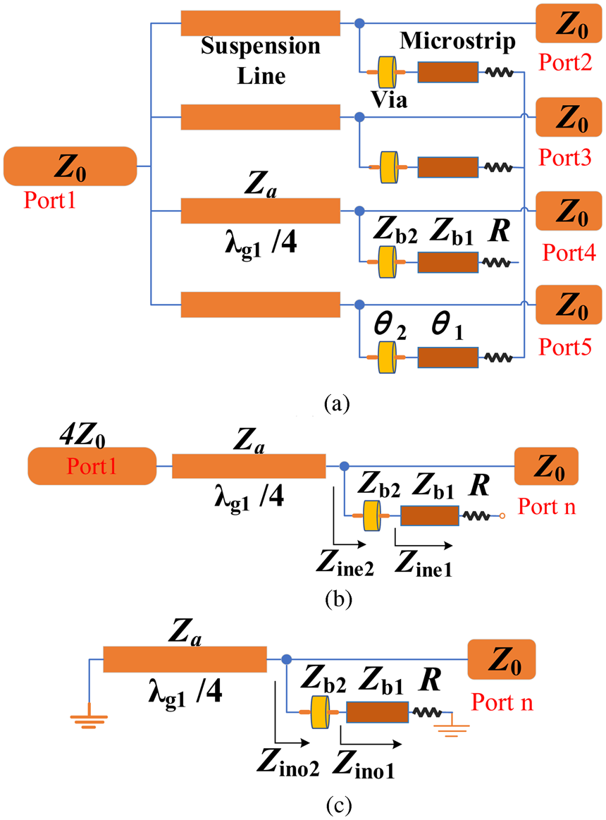
Fig. 3. (a) Equivalent circuit of the proposed power divider, (b) even mode, and (c) odd mode.
When the center frequency is determined, the suspended-stripline wavelength λg 1 and the microstrip wavelength λg 2 can be obtained. The electrical length of the high impendence Za suspended stripline is π/2. The length Lg can be further designed. When the length and impendence of the transmission lines through the vias is determined, according to the above formula, the length Lg 1 and width of the isolation microstrip network is easy to be obtained. To obtain good isolation, the transmission lines through the vias are connected to connect the place λg 1/4 of the high impedance suspended-striplines. And the two-step impedance lines are used to obtain good impedance matching of input and output ports respectively.
Figure 4 shows the input return loss S 11 and output return loss S 33 with different Ø 3. It can be seen that the input and output return loss can adjust greatly by altering Ø 3. When the diameter Ø 4 of the inner conductor is initially identified, by properly adjusting Ø 3, good impedance matching is obtained. When Ø 3 is varied, the input and output return loss is changed greatly, as shown in Fig. 4.
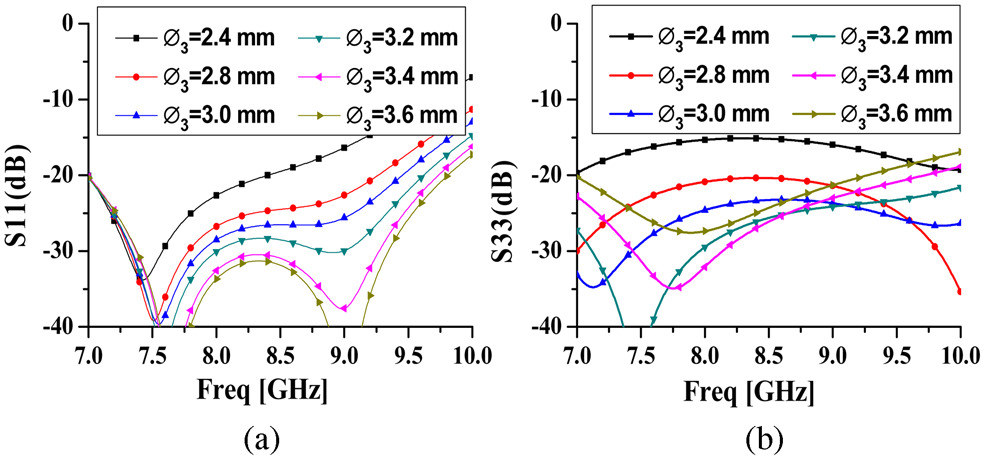
Fig. 4. (a) Input return loss and (b) output return loss with varied Ø 3.
Results and discussion
A four-way suspended-stripline power divider was designed according to the aforementioned analysis. It was simulated and optimized in the full-wave simulation software HFSS. The four-way power divider has been fabricated by machining of the suspended-stripline in the copper blocks and the microstrip line on the substrate Taconic RF-35 with a relative dielectric constant of 3.5, a thickness of 0.508 mm, and a loss tangent of 0.0018. The final dimensions of the proposed power divider is as follows: Wt 2 = 2.49 mm, Wt 1 = 4.67 mm, Lt 2 = 2.45 mm, Lg = 9 mm, Wp 1 = 3.42 mm, Wp 2 = 4.91 mm, Lp 2 = 3.87 mm, Lp 1 = 1.13 mm, Win 1 = 1.00 mm, Lin 1 = 3.88 mm, Lin 2 = 3.5 mm, Win 2 = 1.88 mm, Wg 1 = 0.52 mm, Wg 2 = 0.45 mm, Ø 3 = 3.14 mm, Ø 4 = 1.00 mm, Ø 1 = 2 mm, Lg 1 = 7.72 mm. The resistance is 50 Ω and is selected from Barry's high-power resistors. The photograph of the fabricated suspended-stripline power divider is shown in Fig. 5(d).

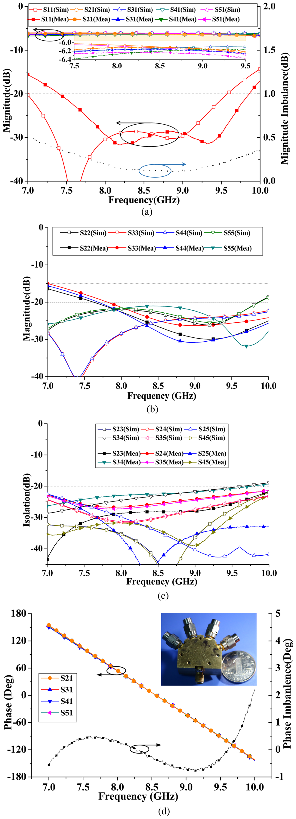
Fig. 5. Simulated and measured results of the proposed power divider: (a) input return loss and insertion loss, (b) output return loss, (c) isolation, and (d) phase.
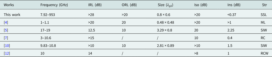
The fabricated power divider has been measured by using an Agilent N5244A network analyzer. The simulated and measured results are presented in Fig. 5. It can be seen that the measured results agree with the simulated ones over the entire operating frequency range. The measured 20-dB input return loss bandwidth is 2.45 GHz (from 7.40 to 9.85 GHz). Moreover, the measured input return loss is greater than 28 dB from 7.92 to 9.53 GHz. The measured insertion loss is less than 0.37 dB from 7.5 to 9.5 GHz while the measured magnitude imbalance is less than 0.5 dB. As shown in Fig. 5(b), the output return loss is greater than 20 dB from 7.82 to 9.86 GHz. The output isolation is greater than 20 dB from 7 to 9.77 GHz, as shown in Fig. 5(c). Meanwhile, the measured phase imbalance between the output ports is less than ± 0.7°. The measured results and the simulated ones show a reasonable agreement with each other. As can be seen, the differences between the simulated and measured results are due to the welding and manufacturing error of the power divider. The comparison with others' four-way power dividers is shown in Table 1. It can be seen that the presented suspended-stripline power divider has the advantages of low insertion loss, relatively high isolation, and good input/output return loss.
Table 1. Comparisons between the proposed power divider and the reported ones
Conclusion
In this letter, a four-way suspended-stripline power divider is demonstrated. The circuit model and the performance of the simulated and measured results have been introduced and discussed. The measured results are in good agreement with the simulated ones. The proposed four-way suspended-stripline power divider has low insertion loss, good input/output return loss, compact size, and high isolation. The proposed power divider can be used to multiway power-combining amplifiers, antenna array, mixer, and so on.
Acknowledgement
This work was supported by the National Natural Science Foundation of China (Grant No: 61771094)
 Song Guo was born in Lang Fang, Hebei Province, China, in February 1993. He received the B.Sc. degree in Microelectronics from Harbin Engineering University, Harbin, Heilongjiang, China, in 2006, and is currently working toward the M.Sc. degree in electromagnetic fields and microwave technology at UESTC (University of Electronic Science and Technology of China). His research interests include microwave and millimeter-wave power-combining technology and microwave passive component design.
 Kaijun Song received the M.S. degree in radio physics and the Ph.D. degree in the electromagnetic field and microwave technology from the University of Electronic Science and Technology of China (UESTC), Chengdu, China, in 2005 and 2007, respectively. In 2011, he received the “New Century Excellent Talents in University Award” from Chinese Ministry of Education. In 2015, he received the academic and technical leaders in Sichuan province. In 2019, he received the science and technology innovation talents in Sichuan province. Since 2007, he has been with the EHF Key Laboratory of Science, School of Electronic Engineering, UESTC, where he was a full Professor. From 2018, he is currently a full Professor with School of Electronic Science and Engineering, UESTC. From 2007 to 2008, he was a postdoctoral research fellow with the Montana Tech of the University of Montana, Butte, USA, working on microwave/millimeter-wave circuits and microwave remote sensing technologies. From 2008 to 2010, he was a research fellow with the State Key Laboratory of Millimeter Waves of China, Department of Electronic Engineering, City University of Hong Kong, on microwave/millimeter-wave power-combining technology and Ultra-Wideband (UWB) circuits. He was a senior visiting scholar with the State Key Laboratory of Millimeter Waves of China, Department of Electronic Engineering, City University of Hong Kong in November 2012. He has published more than 200 internationally refereed journal papers and conference papers. His current research fields include microwave and millimeter-wave/THz power-combining technologies; high-power solid-state microwave/millimeter-wave technologies; UWB circuits and technologies; and microwave/millimeter-wave devices, circuits, and systems. Prof. Song is the Reviewer of tens of international journals, including IEEE Transactions and IEEE Letters.
 Yong Fan (M’05) received the B.E. degree from Nanjing University of Science and Technology, Nanjing, Jiangsu, China, in 1985 and the M.S. degree from University of Electronic Science and Technology of China, Chengdu, Sichuan, China, in 1992. He is now with the School of Electronic Engineering, University of Electronic Science and Technology of China, where he is currently a full Professor. His current research interests include electromagnetic theory, millimeter-wave technology, communication and system. He has authored and co-authored over 130 papers. Mr. Fan is a senior member of the Chinese Institute of Electronics.