


Introduction
Nowadays, the impact of wearable devices is unquestionable and beyond doubt. This is because of the tremendous growth of applications requiring highly operational and efficient wearable devices that can serve, either or both, on-body and off-body communications [Reference Peter and Yang1]. Military, sports, emergency rescue missions, and smart wrist wearable gadgets [Reference Yen and Ting2–Reference Sherif, Mahmoud and Abdelhamid7] are only a few number of wearable applications.
To meet the demands of those applications, the wearable antenna should hold wearable-related characteristics, such as compactness, flexibility, and robustness against extreme bending scenarios, high gain, and low specific absorption rate (SAR). Reported in the literature are a number of techniques to attain such features. Primarily, the wearable antennas are classified as either monopole or patch-based. For achieving low profile radiators, [Reference Adel, Zuhairiah, Samsul, Huda, Shaharil, Muhammad and Akram8–Reference Mohamed, Mahmoud and Hadia10] applied modifications to the radiator geometry, [Reference Zhi, Zheng and Taiwei11] slotted the radiator at its center, [Reference Mohamed, Mahmoud and Hadia12] wound the radiator entire length, and [Reference Sen and Guy13] designed a radiator based on the composite right/left-handed transmission line methodology. As for achieving flexibility, it mainly depends on the conformable material type utilized. Textiles [Reference Sherif, Mahmoud and Abdelhamid7, Reference Adel, Zuhairiah, Samsul, Huda, Shaharil, Muhammad and Akram8, Reference Linda, Ping and Sen14, Reference Sen, Ping and Guy15], ultra-thin polyimides [Reference Sherif, Mahmoud and Abdelhamid6, Reference Mohamed, Mahmoud and Hadia10–Reference Mohamed, Mahmoud and Hadia12, Reference Saud, Constantine and Craig16–Reference Sherif, Mahmoud and Abdelhamid21], composite materials [Reference Zhi, Zheng and Taiwei11], papers [Reference Simone, Filippo and Filippo22–Reference Benjamin and Atif24], and flexible FR-4 [Reference Negi, Khanna and Kaur25] are the main substrates for mounting the radiators on.
Because the antenna is functioning nearby the human body, it is essential to take into consideration the amount of radiation absorbed by the human body. The factor that accounts for such amount of radiation is acknowledged as SAR. It can be determined from (1), where σ points to the human tissue conductivity, E characterizes the near-field electric field, and ρ specifies the human tissue mass density. SAR has two well-known limits; the first is set by the Federal Communications Commission (FCC) at a threshold of 1.6 W/kg, averaged over 1 g tissue, and is referred to as the American standard. The second is set by the International Electrotechnical Commission (IEC) at a maximum of 2 W/kg, averaged over 10 g tissue, and is referred to as the European standard.

To attain high gain, as well as low SAR, simultaneously, when assessing the antenna performance within the vicinity of the human body, artificial magnetic conductor structures (AMCs), often termed electromagnetic band gap or high impedance surface (HIS), have been heavily relied on [Reference Yen and Ting2, Reference Adel, Zuhairiah, Samsul, Huda, Shaharil, Muhammad and Akram8–Reference Zhi, Zheng and Taiwei11, Reference Saud, Constantine and Craig16–Reference Haider, Ayman and Hussain20, Reference Simone, Filippo and Filippo22–Reference Negi, Khanna and Kaur25]. Another approach is to simply utilize a large ground plane [Reference Sen and Guy13, Reference Roy, Asimina and Karu26, Reference Dalia, Ahmed and Esmat27]. However, since the ground plane is a perfect electric conductor, it experiences out-of-phase reflection properties with the incident plane wave. This results in substantial total efficiency reduction and large amounts of antenna near-field energy storage [Reference Dan, Lijun and Romulo28]. An interesting technique relies on increasing the separation between the wearable antenna and the human body, as reported in [Reference Sherif, Mahmoud and Abdelhamid7, Reference Mohamed, Mahmoud and Hadia12]. However, there is a trade-off experienced in terms of antenna performance parameters and low SAR, besides the large overall size due to the large gap separation.
Thus, proposed in this paper is an extension to the work presented in [Reference Mohamed, Mahmoud and Hadia12], where the asymmetric meander line antenna (AMLA), mounted on an ultra-thin Rogers ULTRALAM 3850 substrate, is backed by a 1 × 2 textile-based AMC array, targeting human hand applications. Such a structure is low profile, flexible, and displays high gain and low SAR when operating at close distances to the human hand-wrist. The procedure behind choosing the certain size and substrate material of the AMC is discussed in section “The AMLA-backed textile AMC design” along with the free space performance of the integrated design. Finally, the integrated design flat case and bent case scenarios are studied and analyzed in section “The integrated design hand results”.
The AMLA-backed textile AMC design
Displayed in Figs 1(a) and 1(b) are the AMLA layout and fabrication prototype, respectively, where the details on how this design was attained and its performance in free space are covered in [Reference Mohamed, Mahmoud and Hadia12]. In [Reference Mohamed, Mahmoud and Hadia12], a human hand three-layered cubic model was used to assess the AMLA SAR performance for wrist applications; however, in this work, an actual human hand model is incorporated in the 3D full-wave simulator Computer Simulation Technology (CST). The human hand model is of the specific anthropomorphic mannequin (SAM) human model phantom, which is readily available in the libraries of CST software tool. It is homogenous-based and is composed of a liquid, which imitates the tissue, and is covered by a shell. The SAM phantom head and hand tissue's dielectric properties are determined by averaging those of an anatomical head and hand. It possesses a relative permittivity of 37.005, conductivity of 2.0249 S/m, and mass density of 1090 kg/m3. Simulation was conducted using the CST time-domain transient solver along with a hexahedral mesh type for partitioning the domain and achieving accurate outcomes. The advantage of incorporating the SAM hand model in the simulations is that it is time efficient in calculating the SAR.
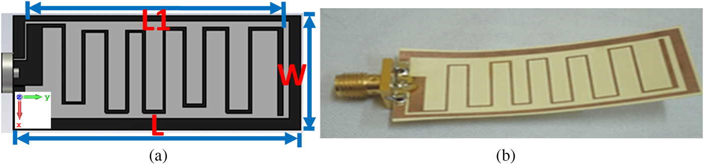
Fig. 1. The 2D layout geometry of: (a) asymmetric meander line antenna (W = 20 mm, L = 50 mm, L 1 = 47.7 mm); (b) fabricated prototype.
Distanced by 10 mm, the maximum SAR level achieved, averaged over 10 g of tissue, is 5.05 W/kg which is far beyond the limit of 2 W/kg, as illustrated in Fig. 2. To circumvent this, an AMC array structure was designed as a reflector to reduce the SAR.

Fig. 2. The AMLA maximum SAR, averaged over 10 g of tissue, at 2.4 GHz.
The textile AMC unit-cell design
The incorporated AMC is designed by etching a cross-shaped slot at the square patch center, as displayed in the top view of the unit-cell design and fabricated prototype in Figs 3(a) and 3(b), respectively. The initial dimensions were found using (2) and were optimized so that it operates at 2.4 GHz.


Fig. 3. The layout top view of: (a) the textile AMC unit-cell (L 1 = 20 mm, L 2 = 2 mm, L 3 = 0.45 mm, Lg = 25.7 mm); (b) the fabricated textile AMC array design.
A cross-shaped slot was purposely designed and etched to further reduce the overall AMC structure. This is due to the fact that the etched cross-slot increases the path for current to travel leading to a corresponding increase in the inductance, which results in a reduction in size, as per (2). The unit-cell characteristics are displayed in Figs 4 and 5. Observing the left-hand scale (solid black) of Fig. 4, the designed unit-cell achieves 0° reflection phase at 2.4 GHz, with −90° to +90° bandwidth achieved from 1.44 to 2.66 GHz. On the other hand, the right-hand scale illustrates the impedance, where a high impedance of 7 kΩ is attained at 2.4 GHz. Furthermore, Fig. 5 depicts the dispersion diagram associated with an AMC unit-cell, where a band gap is exhibited at 2.4 GHz.

Fig. 4. The reflection phase (solid black) and impedance (dotted red) of the AMC unit-cell.
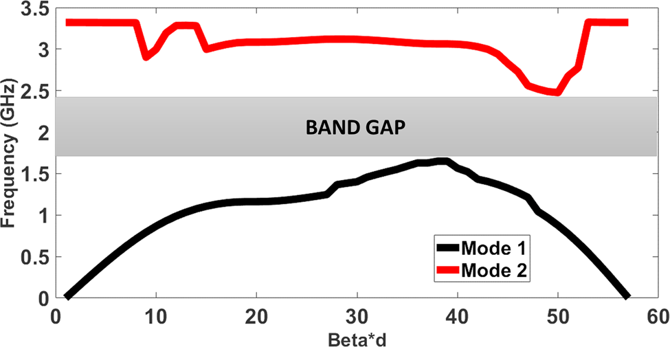
Fig. 5. The dispersion diagram of the AMC unit-cell.
Study of different AMC sizes and substrate materials
Subsequently, a study of AMC sensitivity test was conducted to determine the suitable size and the rationale behind such size of the AMC array, in terms of reflection coefficient, realized gain, and total efficiency performance parameters, as shown in Fig. 6 and Table 1, respectively. The different array sizes under test included 1 × 2, 2 × 2, 3 × 2, 2 × 3, and 3 × 3 unit-cells. As depicted in Fig. 6, when the AMLA was backed with a 1 × 2 AMC array (solid black), with an in-between separation of 5 mm, the achieved resonant frequency is 2.4 GHz, while the others were shifted downwards, due to the capacitive effects in-between both structures, as reported in [Reference Mantash, Tarot, Collardey and Mahdjoubi29, Reference Hadarig, Cos and Las30]. Moreover, inspecting Table 1, a realized gain and total efficiency of 6.76 dBi and 88.4%, respectively, were achieved with the backed 1 × 2 AMC array, which is clearly higher than those of other sizes.

Fig. 6. Comparison in terms of simulated reflection coefficients between the integrated design different AMC sizes.
Table 1. Comparison between different AMC sizes in terms of realized gain and total efficiency at 2.4 GHz
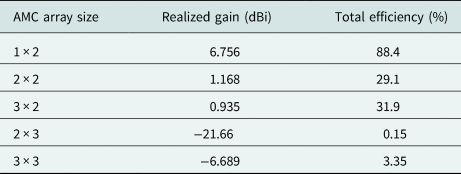
This could also be because of the fact that with the increase in the AMC array size, the electrical conductivity is increased due to the more number of cells. It is well known that with the increase in the conductivity, the total antenna efficiency is reduced because of the conduction losses, as was tabulated in Table 1. Despite the high directivity associated with the integrated design, since by backing the monopole antenna with an AMC array structure, the integrated design displays a uni-directional radiation pattern, the gain decreased. This is because of the relation between gain, efficiency, and directivity, where gain (in dB) is the addition of the efficiency (in dB) with the directivity (in dB). As such, the gain will decrease with the decrease in the total efficiency.
Another study was conducted on the type of substrate material, which is considered a contribution of the proposed work. For attaining flexibility and integrating with clothes, textile was chosen as the AMC material. However, other substrate materials, such as Rogers 5880 and FR-4, were studied to get an understanding of the textile benefits in addition to flexibility. For the textile case, the conductive parts of the AMC array, patch and ground plane, are based on the conductive ShieldIt Super [31]. It is 0.17 mm thick with an approximate conductivity of 1.18 × 10⁵ S/m. The dielectric substrate in-between is made of Felt [32]. It is 3 mm thick with a relative permittivity of 1.2 and a loss tangent of 0.044. For the Rogers 5880 case, its relative permittivity and loss tangent are 2.2 and 0.0009, respectively, with a thickness of 0.8 mm. Finally, for the FR-4 case, its relative permittivity and loss tangent are 4.3 and 0.025, respectively, with a thickness of 1.6 mm. All simulations were conducted with the same air-gap separation of 5 mm in-between the AMLA and 1 × 2 AMC array structures. As displayed in Fig. 7 and Table 2, when the AMLA was backed with a 1 × 2 textile-based AMC array (solid black), the achieved resonant frequency is 2.4 GHz, which is not the case with the other material types. Moreover, the corresponding realized gain and total efficiency are much higher than those of Rogers 5880 and FR-4, as tabulated in Table 2. This is because Felt, the dielectric textile, possesses a low relative permittivity of 1.2, which helps in reducing the losses of the surface waves. In other words, the spatial waves are increased leading to antennas with high gain and suitable efficiency, as stated in [Reference Rita, Caroline, Ricardo and Pedro33].

Fig. 7. Comparison in terms of simulated reflection coefficients between the integrated design different AMC substrate materials, with inset of integrated design, and measured reflection coefficient.
Table 2. Comparison between different AMC substrate materials in terms of realized gain and total efficiency at 2.4 GHz

Integrated design free space results and analysis
Therefore, presented in Fig. 3(b) is the 1 × 2 all-textile AMC array, with a footprint of 50.7 mm × 25.7 mm, where fabrication was conducted using manual cutting tools. Alongside manual cutting, ironing was involved to adhere to the ShieldIt Super layers to the Felt one. This is due to the hot melt adhesive back associated with the ShieldIt Super layers. After that, the proposed AMLA was integrated into the proposed 1 × 2 all-textile AMC array, where the separation in-between is realized by foam, forming the integrated design. The top view is displayed in the inset of Fig. 7.
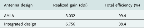
To validate the simulated reflection coefficient result, the fabricated integrated design, including the 5 mm foam, reflection coefficient was measured in free space and plotted in Fig. 7 (dotted red). It attained resonance at 2.4 GHz, thus agreeing and matching with its simulated counterpart. A frequency of 2.4 GHz was selected as the operating frequency in order to transmit the subject's medical symptoms through the Wi-Fi wireless connection. The AMLA, without the AMC array, is benchmarked against the proposed integrated design, including the AMC array, in Table 3, with respect to realized gain and total efficiency. In free space, the integrated design displayed an enhancement in the realized gain by 3.73 dBi, with a slight reduction in the total efficiency.
Table 3. Comparison between AMLA and integrated design in free space in terms of realized gain and total efficiency at 2.4 GHz
The integrated design hand results
Flat case performance and analysis
The integrated design was placed over the human hand model, as displayed in the inset of Fig. 8. Moreover, illustrated as an inset in Fig. 8 is the Vector Network Analyzer (VNA) device. Specifically, Rohde & Schwarz ZVB20 VNA was used for measuring the reflection coefficient of the integrated design in the flat condition. The integrated design maintained its 2.4 GHz resonance, as per the simulated and measured results, with a good impedance matching performance, at a close distance of 3 mm from the human wrist. This distance accounts for the smart gadget cover. In addition, the realized gain and total efficiency are 4.06 dBi and 44.39%, respectively. The integrated design performance results are benchmarked against the AMLA, without the AMC, for the human hand scenario, in Table 4. As tabulated, the integrated design displayed a gain and total efficiency enhancements of 3.03 dBi and 16.5%, respectively, courtesy of the incorporated AMC array. This signifies that the back radiation, toward the human hand, is further reduced, and the FBR is further enhanced as well. With the same input transmittal power level of 100 mW, the integrated design SAR level was evaluated. With the addition of the AMC array, the integrated design exhibited a maximum SAR of 1.8 W/kg, averaged over 10 g of tissue; thus, it complies with the standard, as depicted in Fig. 9. In comparison with the outcome obtained in Fig. 5, the integrated design achieved a SAR reduction of 64.4%.

Fig. 8. The integrated design simulated and measured reflection coefficients at 3 mm from the human hand model, with inset of measurement setup.
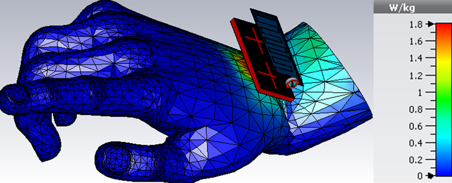
Fig. 9. The integrated design maximum SAR, averaged over 10 g of tissue, at 2.4 GHz.
Table 4. Comparison between AMLA and integrated design against human hand in terms of realized gain and total efficiency at 2.4 GHz

Bent case performance and analysis
Since the integrated design is constructed based on flexible materials, it was essential to check the performance of the bent design against the human hand model. The setup is displayed in the inset of Fig. 10, where the 3 mm distance in-between accounts for the smart gadget cover. Moreover, illustrated as an inset in Fig. 10 is the same VNA device (Rohde & Schwarz ZVB20), which was used for measuring the reflection coefficient of the integrated design in the bent condition. The integrated design displayed resonance at 2.4 GHz with good impedance matching performance, according to the simulated and measured outcomes which highly agree. However, it is noticeable that the measured result is slightly wider with a much better impedance matching. Furthermore, the obtained realized gain and total efficiency are 2.83 dBi and 36.33%, respectively.

Fig. 10. The bent integrated design simulated and measured reflection coefficients against the human hand model, with inset of measurement setup.
Finally, the SAR of the bent integrated design was evaluated, with the input power to the integrated design fixed at 100 mW. The bent integrated design exhibited a maximum SAR of 0.521 W/kg, averaged over 1 g of tissue and 0.406 W/kg, averaged over 10 g of tissue. As such, it complies with both the American and European standards, as depicted in Figs 11(a) and 11(b), respectively.

Fig. 11. The bent integrated design maximum SAR, at 2.4 GHz, averaged over: (a) 1 g of tissue; (b) 10 g of tissue.
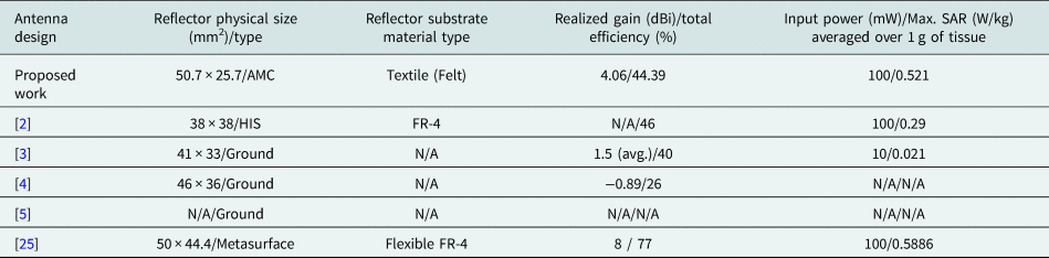
Tabulated in Table 5 is a comparison between the presented work and other recent wrist-wearable published antennas. Comparison criteria include the reflector physical size and type, reflector material type, realized gain, total efficiency, input transmittal power to the antenna, and maximum SAR level, averaged over 1 g of tissue, attained against the hand-wrist. As observed in Table 5, the proposed work reflector is of the lowest profile compared to the published ones, in addition, to being more flexible due to the incorporated textile material. This proves its compactness and flexibility required for such an application. Performance wise against the human hand-wrist, the proposed integrated design displayed a high realized gain while falling second to [Reference Negi, Khanna and Kaur25]. In terms of efficiency, it is near to [Reference Yen and Ting2], but lower than [Reference Negi, Khanna and Kaur25]. Furthermore, with the same input power of 100 mW, the proposed integrated design achieved a very low SAR value, but falling second compared with [Reference Yen and Ting2].
Table 5. Comparison between the proposed work and published wrist-wearable work against the human hand at 2.4 GHz
Conclusion
An integrated design consisting of a compact AMLA, 50 mm × 20 mm, and a low profile 1 × 2 textile AMC, 50.7 mm × 25.7 mm, spaced apart by 5 mm, was presented at 2.4 GHz. The AMLA, without the AMC array, performed well in free space, but suffered, in terms of realized gain, total efficiency, and SAR, when placed within the vicinity of the human hand model. As such, to maintain low profile and flexibility, the AMLA was backed with a textile AMC. The integrated design displayed gain enhancements, in free space, and against the SAM human hand model, distanced by 3 mm, as well as SAR reduction. Furthermore, it performed well in bent scenarios against the hand. In addition, a study was conducted between different AMC substrate materials, where it was concluded that the textile-based antenna displayed the highest gain and efficiency performances of all ones under test. Therefore, the proposed flexible and compact integrated design can be highly recommended for wrist-wearable applications and for communicating the patient's medical symptoms information, diagnosed at the wrist, through the Wi-Fi wireless technology. This was the main reason for designing the proposed antenna at a resonant frequency of 2.4 GHz.
 Mohamed El Atrash received B.Sc. (with honors) in electrical engineering from the Electrical Systems Engineering Department, October University for Modern Sciences and Arts (MSA), Cairo, Egypt, in 2011. He also received M.Sc. (with distinction) in wireless mobile communications systems engineering from the University of Greenwich (UoG), United Kingdom, in 2014. Currently, he is pursuing his Ph.D. degree in electrical engineering at Ain Shams University, Cairo, Egypt. His research interests include flexible wearable antennas, high gain, thin, low profile antennas, and EBG/AMC design. Research studies enabled him to publish articles in IEEE Transactions on Antennas and Propagation, IET Microwaves, Antennas & Propagation, and the International Journal of Microwave and Wireless Technologies, as well as, a number of conference papers. He is a reviewer for the journal IET Microwaves, Antennas & Propagation, and has reviewed 12 journals.
 Mahmmoud A. Abdalla was born in 1973, received B.Sc. and M.Sc. in electrical engineering from Military Technical College, Cairo, Egypt in 1995 and 2000. He received the PhD degree from School of Electrical Engineering, University of Manchester, UK, in 2009. He is now a professor leading the electromagnetic waves group in Electronic Engineering Department, Military Technical College. Dr. Mahmoud was the recipient of Egyptian encouragement state prize for engineering sciences in 2014. He has published more than 200 peer-reviewed journal and conference papers. His research focused on miniaturized, multiband and wideband microwave/millimeter antennas and componennts and also absorbing materials employing metamaterial/EBG, structures. He is a senior member of the IEEE/URSI and the European Microwave Association EuMA. He is a reviewer in many high ranked journals where he was awarded the top 1% Publon worldwide reviewer award for 2018 and 2019.
 Hadia M. Elhennawy received B.Sc. and M.Sc. from Ain Shams University, Cairo, Egypt, in 1972 and 1976, respectively, and Doctorate of Engineering (Dr.-Ing.) degree from the Technische Universitat Braunschweig, Braunschweig, Germany, in 1982. Since 1992, she has been a Professor of communication engineering with the Electronics and Communications Engineering Department, Ain Shams University. In 2004, she became a Vice-Dean for graduate study and research. In 2005, she became the Dean of the Faculty of Engineering, Ain Shams University. Her research interests include microwave devices and subsystems, as well as filters and antennas for modern radar and wireless communications applications.


