


Introduction
In order to realize single frequency full-duplex (SFFD) also termed as in-band full-duplex (IBFD) wireless operation with its full gains, the IBFD transceiver should cancel the self-interference (SI) at the receiver side (which is induced by its own transmitter) to the receiver's noise floor [Reference Bharadia, McMilin and Katti1–Reference Korpi3]. Normally, the amount of suppressed SI is deemed as a figure of merit for SFFD radio transceiver design [Reference Maraševic, Zhou, Krishnaswamy, Zhong and Zussman2, Reference Korpi3]. The residual SI acts as a noise and decreases the signal to noise ratio which results in degradation to achievable throughput of full-duplex wireless operation [Reference Bharadia, McMilin and Katti1]. The intended levels of SI suppression depend on the radiated power and bandwidth (BW) of transmitted signal in addition to received noise power (Prn) at receiver. For example, the received noise power (Prn) for the receiver with 20 MHz BW and 11 dB noise figure (NF) are computed as [Reference Korpi3, Reference Anttila, Korpi and Syrjälä4]:


Based on (1) and as depicted in Fig. 1, if the transmitted power (Pt) for a radio transceiver is 10 dBm, then the required amount of SI suppression should be 10 dBm-(−90 dBm) = 100 dB so that received signal is not disturbed by RF leakage from its own transmitter (which is termed as SI in IBFD wireless communication context).

Fig. 1. Achieving around 100 dB self-interference cancellation (SIC) for an IBFD transceiver employing a monostatic antenna with 70 dB interport isolation.
A large amount of SI suppression is required at the antenna stage to prevent the radio receiver to become saturate due to excessive SI [Reference Bharadia, McMilin and Katti1–Reference Korpi3, Reference Nawaz and Tekin5]. As depicted in Fig. 1, if we achieve around 70 dB SI suppression or SI cancellation (SIC) at antenna stage which is the case with our proposed antenna, then only 30 dB SIC using digital base-band techniques can achieve the total intended 100 dB isolation enabling the full-duplex operation at same transmit and receive carrier frequency without using complex and bulky analog RF domain SIC topologies. In addition, the non-linear components of SI (resulting from nonlinearities in Tx chain) and transmitter noise is also required to be suppressed [Reference Bharadia, McMilin and Katti1, Reference Anttila, Korpi and Syrjälä4].
The basic configuration of a dual-polarized, dual-port patch antenna is normally based on a square-shaped element with two perpendicular ports for excitation of vertical and horizontal polarizations for respective port excitation. Such dual-polarized antenna designed on 1.6 mm thick FR-4 substrate can offer ~30–35 dB Tx–Rx port–port isolation [Reference Nawaz and Tekin5]. Moreover, hybrid feeding can be employed for such dual-polarized antennas to improve the interport isolation on the cost of additional complexity [Reference Nawaz and Tekin5]. For instance, one such topology is reported in [Reference Nawaz and Tekin5], where one port excites the patch through thin quarter-wave feed line and slot coupling is deployed for other polarization modes to achieve ~ 15–20 dB additional isolation. The microstrip-T can also be used instead of thin quarter-wave feed to achieve almost the same levels of interport isolation for such antennas with hybrid feeds [Reference Amjad, Nawaz, Özsoy, Gürbüz and Tekin6]. The interport coupling can also be reduced through a defected ground structure as reported for an antenna presented in [Reference Younkyu, Seong-Sik and Ahn7].
An external single or multi-taps SIC circuitry can be used with dual-port, dual-polarized antenna to suppress the Tx leakage at Rx port [Reference Nawaz and Tekin8–Reference Nawaz, Gürbüz and Tekin11]. These SIC techniques are based on signal inversion mechanism where Tx signal is tapped and its modified version is subtracted from the coupled signal at Rx port. The achievable isolation levels with such techniques are highly dependent on the accuracy and resolution of active components in Tx signal modification channel. Moreover, such SIC topologies are inherently narrow-band and provide cancellation within very limited BW (few MHz) as detailed in [Reference Nawaz and Tekin8, Reference Nawaz, Gürbüz and Tekin9]. The two-taps circuitry can achieve comparatively wider SIC BW as reported for antennas in [Reference Kolodziej, McMichael and Perry10, Reference Nawaz, Gürbüz and Tekin11].
Different excitation networks can also be used along with balanced circuitry to generate two orthogonal for Tx and Rx modes with reduced coupling and cross-polarization levels. However, such antenna designs are mostly based on the multi-layered printed circuit board (PCB) structures and complex balanced feed networks [Reference Deng, Li and Zhang12]. The SIC can also be performed through an extra signal path to achieve improved interport isolation. For example, the dual-port antenna reported in [Reference Zhang and Wang13] is based on Tx leakage suppression through an additional signal path to obtain 20 dB interport isolation within 1.85–2.62 GHz frequency range. The cross-polarized antennas with improved interport isolation between DC isolated feeding ports are required for active integrated antenna topologies [Reference Chang, York, Hall and Itoh14]. These types of antennas are also used for the implementation of retrodirective arrays [Reference Luxey and Laheurte15] or amplifying-reflect arrays [Reference Bialkowski and Song16]. Previously reported antennas for such application have employed electromagnetic coupled (proximity feeding etc.)-based excitation or multilayered structures. The monostatic antennas with DC isolated ports will neither require DC blocking series capacitors at the output of Tx chain nor at the input of Rx port of radio transceiver. The dual-polarized antennas with high port–port isolation can effectively mitigate the fading effect for GSM and LTE bands mobile applications as discussed in [Reference Puente, Anguera and Borja17]. The differential feeding is a very useful SIC technique to achieve high Tx–Rx isolation without degrading the radiation performance of monostatic antennas. The differential feeding can be used either at Tx/Rx or simultaneously at both ports [Reference Nawaz and Tekin18–Reference Nawaz and Umar Niazi21]. The achievable SIC performance of differentially driven antennas is dependent upon the antennas symmetry and the response of the employed differential circuit. Moreover, the coupling between the radiating structure and differential circuit also limits the achievable isolation. The 3 dB/180o ring hybrid coupler with very nice amplitude and out-of-phase balance characteristics is a good choice for differential excitation of dual-polarized antennas to achieve high interport isolation.
The presented antenna topology is based on three ports patch with three symmetrically placed ports exciting the patch through thin quarter-wave (λ g/4) feed lines. Two Rx ports are dual linear polarized with respect to a Tx port which results in the same amount of coupling for each pair of Tx–Rx ports. The differentially driven Rx mode through designated ports of antenna effectively suppresses the Tx leakage at Rx port through signal inversion mechanism without degradation in radiation characteristics of the antenna. The intended differential excitation is realized through a simple and well balanced 3 dB/180o ring hybrid coupler. The designed hybrid coupler has an excellent amplitude and out-of-phase balance response for the BW of interest (antenna's 10 dB return loss impedance BW). Consequently, the SI is well suppressed by the employed differential circuit within the intended range of frequencies. The theoretical analysis using simple circuit theory is also presented for employed SIC topology. The dependence of achievable SIC levels on amplitude and phase response of the differential circuit is analytically analyzed too. The validation model for the proposed antenna is realized with two-layered PCB. The patch with co-planar feeds is etched on the top of dielectric layer 1 and the differential circuit is implemented on bottom of dielectric layer 2 with shared ground plane sandwiched between two layers of substrate. The interconnections are made through small vias. This architecture results in compact antenna design and reduced PCB size. In addition, as compared to reported work in [Reference Nawaz and Tekin18], this design achieves better interport isolation performance. The implemented antenna demonstrates ~10 dB additional isolation in 50 MHz BW compared to the reported antenna in [Reference Nawaz and Tekin18]. The reason is that the achievable SIC performance is limited by strong coupling between the coupler and co-located radiating element for the antenna design reported in [Reference Nawaz and Tekin18]. However, for stacked PCB design in current work, the patch and SIC circuit are electromagnetically isolated through the sandwiched ground plane. So here, the improvement in isolation is attributed to the reduced coupling between the patch and SIC circuit.
2.4 GHz Dual-polarized antenna with differentially driven Rx mode
The presented dual-polarized, 2.4 GHz antenna comprises three ports square patch antenna with quarter-wave (λ g/4) feeds as shown in Fig. 2 below. The proposed antenna has been designed on 1.6 mm thick single-layered FR-4 substrate (ɛr = 4.4, tanδ = .02) as indicated in Fig. 2. The port 1 is for transmit (Tx) mode while port 2 and port 3 will be used for differential-driven receive (Rx) mode. Due to the symmetry of the proposed antenna, the same amount of SI or RF power is leaked from Tx to each of Rx port.

Fig. 2. Three ports microstrip patch antenna with a transmit port and pair of Rx ports which will be used for differential receive mode for self-interference suppression.
Each Rx port is orthogonally linearly polarized with respect to Tx port (port 1) and as reported in [Reference Nawaz and Tekin5], the interport isolation between each pair of Tx–Rx ports will be around 35 dB for such single-layered antenna designed on 1.6 mm thick FR-4 substrate. The differential excitation through Rx ports can suppress the Tx leakage to achieve additional isolation on the top of intrinsic isolation of polarization diversity as detailed through the following analysis. Let us denote IRx 1 and IRx 2 as currents flowing out of Rx ports and they are related with input current ITx (current flowing in to Tx port) through following equations:

where S 21 and S 31 are the magnitudes of coupling co-efficients for respective pair of Tx–Rx ports.
With the differentially driven Rx port, the total current IRx flowing out will be given as:

Based on (3), the interport current coupling and isolation transfer functions are given as:


As stated earlier, based on the symmetry of the proposed antenna, the same amount of SI or RF power results from Tx to each of Rx port. For perfect or ideal symmetrical structure S 21 = S 31.This will result in perfect cancellation of SI at Rx port to provide infinite interport isolation based on (5) if an ideal differential circuit is employed. However, in reality for a carefully designed antenna S 21 ≈ S 31, excellent SIC levels can be obtained when a differential circuit with nice amplitude and phase balance characteristics is employed with proposed three ports antenna and both are electromagnetically isolated.
The dependence of achievable SIC levels on the amplitude and an out-of-phase imbalance of differential circuit is analyzed graphically as illustrated in Fig. 3. The plot in Fig. 3 provides the difference (in dB) between two same frequency AC signals with different magnitude and phase values. The magnitude and phase difference between two signals is termed as magnitude and phase errors of the differential feeding network (DFN). As expected and stated earlier, the difference (in dB) or SIC levels are highly dependent on both magnitude and phase errors as clear from Fig. 3. For instance, the SIC levels are reduced from 45 dB to around 37 dB for two out-of-phase signals with 0.1 dB magnitude error. Similarly, the SIC levels are reduced from 35 dB to 30 dB for the case of 0.1 dB and 1o phase errors, respectively. However, as indicated in Fig. 3, SIC levels between 30 dB and 45 dB can be achieved through a differential circuit with magnitude error ≤ 0.3 dB and phase error ≤ 1o.

Fig. 3. The illustration of SIC levels dependence on magnitude and phase error of DFN.
The simulated return loss and port–port isolation results for proposed three ports antenna depicted in Fig. 2 are presented in Fig. 4. The three ports antenna was simulated by using Ansoft HFSS13 software. The reference impedance for each port was set to 50Ω for these simulations. As clear from Fig. 4, the ideal differential feeding circuit (having zero magnitudes, phase errors) can provide around 80 dB interport isolation within 10 dB return loss BW of 50 MHz. The simulated peak isolation exceeds 100 dB in this case. So more than 50 dB isolation is provided through differential feeding-based SIC operation on top of 30–35 polarization diversity isolation for 50 MHz BW. The asymmetric behavior of interport isolation is due to low mesh density which was used to save the computational resources and reduce the simulation times.

Fig. 4. The simulated S-parameters for three ports antenna with one Tx port and two Rx ports.
The simulated dual-polarized characteristics of the presented three ports antenna with differential Rx mode are presented in Fig. 5. As clear from simulated surface currents distribution and gain patterns in Fig. 5, the antenna resonates at the same frequency of 2.4 GHz with vertical and horizontal polarization for Tx and differential-fed Rx modes, respectively. The differentially excited Rx mode also achieves reduced cross-polarization levels through the cancellation of higher-order modes and enables the patch to operate with TM 01 and TM 10 modes (fundamental modes of square-shaped radiating patch) only as detailed in [Reference Liang, Zhong and Wang22].

Fig. 5. The simulated surface current distributions and 3D radiation patterns for Tx mode and differential Rx mode of three ports antenna for respective port excitation at f = 2.4 GHz.
A 2.4 GHz, 3 dB/180o ring hybrid coupler has been used for required differential excitation at Rx port. The coupler is used as 3 dB out-of-phase power divider. The hybrid coupler acts as SIC circuit to perform (S 31–S 21) operation when it is connected with three ports antenna and its difference port (Δ port) is used as Rx port. The simulated hybrid coupler achieves excellent amplitude and out-of-phase balance response for BW of interest (antenna's 10 dB return loss impedance BW). Consequently, the SI is well suppressed by the employed differential circuit (hybrid coupler) with an intended range of frequencies. The design details and simulated results of 3 dB/180o ring hybrid coupler are not presented here for brevity.
Antenna prototype and measurement results
The physical model or prototype of the miniaturized dual port, dual-polarized monostatic IBFD antenna with differentially driven Rx mode is shown in Fig. 6. The overall dimensions of the implemented antenna are 75mm × 70 mm as shown in Fig. 6. The validation model was realized by using double-layered FR-4 (ɛr = 4.4, tanδ = .02) dielectric with 1.6 mm thickness of each layer. The three ports patch was etched on top of FR-4 layer 1 while hybrid coupler was placed on the lower side of FR-4 layer 2 as indicated in Fig. 6. The ground plane is placed between two layers of FR-4 substrate. The interconnections are made through small vias. This results in compact antenna design and reduced PCB size. The implemented antenna can be directly connected to single-in single-out transceiver through designated Tx and Rx ports. The Tx and Rx ports of the implemented antenna can be interchanged without degradation in antenna's interport isolation performance. However, the ports of IBFD antenna on a second wireless node should also be interchanged to align the intended polarization of forward and reverse links of dual-polarized full-duplex channel as discussed in [Reference Nawaz and Tekin20, Reference Nawaz and Basit23].

Fig. 6. The physical model of 2.4 GHz differential fed IBFD monostatic antenna.
The performance of the implemented antenna has been characterized through S-parameters and gain measurements for each polarization. The recorded results for S 11, S 22, and Tx–Rx inter-port coupling (S 21) for validation model are presented in Fig. 7. The simulation S-parameters were obtained through Keysight ADS software. The three ports antenna was simulated by using Ansoft HFSS13 software. The 3 dB/180o ring hybrid coupler was simulated in Keysight ADS Momentum software with mesh density = 20 cells/wavelength. The S-parameters for the three ports antenna were imported from HFSS to ADS. Then, the imported S-parameters and EM model of coupler were used in ADS schematic to obtain the simulated S-parameters (S 11, S 22, S 21) for the compact antenna structure.

Fig. 7. The simulated and measured S-parameters (S 11, S 22, S 21) for IBFD antenna.
The physical model or the prototype achieves the shared 10 dB return- loss impedance BW of 50 MHz (2.38–2.43 GHz) for each of Tx and Rx port. The physical model achieves ≥ 70 dB isolation (negative of measured Tx–Rx interport coupling) throughout the 50 MHz BW (spans over 2.38–2.43 GHz). Moreover, the measured peak isolation exceeds 95 dB peak near 2.41 GHz as marked in Fig. 7. Furthermore, better than 80 dB isolation has been observed for the frequency span of 2.4–2.42 GHz (20 MHz BW). Consequently, for 50 MHz BW ~45 dB isolation is contributed by SIC circuit on the top of polarization isolation. The difference between the simulated and measured results can be attributed to the fabrication inaccuracies and the soldering imperfections.
The simulated and experimentally recorded co-polarized and cross-polarized gain patterns for implemented dual port, dual-polarized monostatic IBFD antenna are also recorded and presented in Fig. 8. These patterns have been measured at 2.4 GHz frequency band for both Tx and Rx modes, respectively. The measured gain is better than 4.2 dBi for each of Tx and Rx port as clear from Fig. 8. Moreover, the recorded cross-polarization levels for the prototype are more than 30 and 40 dB below the respective co-polarized levels. Thus, the antenna offers nice gain levels with excellent polarization purity in addition to highly decoupled Tx–Rx ports for IBFD applications.

Fig. 8. The simulated and measured co-polarization and cross-polarization gain patterns for presented monostatic IBFD antenna at 2.4 GHz frequency band.
The measured radiation efficiencies for the presented antenna are given in Fig. 9 for respective Tx and Rx ports excitations with other ports terminated in 50Ω loads. These results were measured through EMSCAN RFxpert near-field measurement configuration for the respective ports. The recorded peak radiation efficiencies are better than 56% for both Tx and Rx ports as clear from Fig. 9. The low radiation efficiencies for the presented antenna are due to the high loss (loss tangent) of FR-4 substrate which was used for antenna implementation. The radiation efficiencies and the resulting gains for Tx and Rx modes of the presented antenna can be improved significantly by using low loss dielectric/substrate as detailed in [Reference Nawaz and Tekin20, Reference Nawaz and Basit23, Reference Nawaz, Basit and Shaukat24].

Fig. 9. The measured radiation efficiencies for the presented antenna when respective Tx and Rx port are excited with other ports terminated in 50 Ω loads.
Dual-polarized antenna with high RF isolation between the DC isolated ports
By replacing the thin λ g/4 feeds with microstrip-T (MS-T) feeds for the presented antenna, the DC isolation between Tx and Rx ports can be achieved in addition to high RF interport isolation [Reference Nawaz and Basit23, Reference Kurup, Rydberg and Himdi25]. Such MS-T feeds excite the antenna through EM coupling and antenna can be effectively used for active applications where DC interport isolation is required [Reference Chang, York, Hall and Itoh14–Reference Bialkowski and Song16]. The simulated S-parameters results for three-port antenna with MS-T feeds are shown in Fig. 10. The proposed antenna achieves around 120 dB peak interport isolation and more than 80 dB port to port isolation for 50 MHz BW as clearly depicted in Fig. 10. The differential feeding can be used for this antenna for Rx mode to achieve high interport isolation between DC isolated ports as presented in [Reference Nawaz and Basit23]. The isolation can be further improved through stacked PCB structure where patch and SIC will be electromagnetically isolated through the ground plane as was the case for antenna presented in previous sections. In that case, the PCB size will also be reduced compared to the antenna design reported in [Reference Nawaz and Basit23].
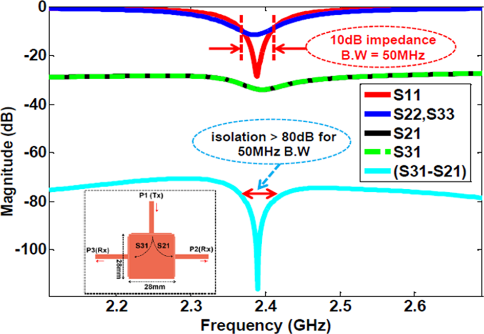
Fig. 10. Simulated port matching (S 11, S 22) and interport isolation (S 12) for three ports patch antenna with microstrip-T feeds to achieve DC interport isolation.
The dimensions and experimentally characterized interport isolation performance of the presented antenna are compared with other monostatic antennas which were reported earlier in [Reference Deng, Li and Zhang12, Reference Nawaz and Tekin18, Reference Nawaz and Tekin20, Reference Nawaz and Basit23, Reference Nawaz, Basit and Shaukat24, Reference Khaledian, Farzami, Smida and Erricolo26]. This comparison is detailed in Table 1 which provides the peak isolation, 10 dB return-loss BW, amount of SIC versus SIC BW, dimensions, type of substrate, number of substrate layers, and peak radiation efficiencies for various prototypes of IBFD monostatic antennas. As clear from Table 1, the validation model of our proposed, dual-polarized monostatic IBFD antenna is more compact as compared to previously reported monostatic antennas. The dimensions of the presented antenna are only (0.6 × 0.55 × 0.03) λ o where λ o is the free space wavelength for 2.4 GHz frequency. The validation model of proposed antenna also offers comparatively better performance in terms of interport isolation versus SIC BW along with very high levels of peak isolation as obvious from Table 1. These enhanced levels of interport isolation for presented compact antenna structure are attributed to effective SIC performed through differential feeding circuit. Moreover, these SIC improvements stem from the electromagnetic isolation (through intermediate ground plane) of monostatic antenna element and associated differential feeding circuit. This electromagnetic isolation offers reduced interport coupling (around 10 dB reduction) as compared to differentially driven antennas reported in [Reference Nawaz and Tekin18, Reference Nawaz and Tekin20, Reference Nawaz and Basit23].
Table 1. The performance comparison of the presented antenna with other monostatic antennas which were reported earlier in [Reference Deng, Li and Zhang12, Reference Nawaz and Tekin18, Reference Nawaz and Tekin20, Reference Nawaz and Basit23, Reference Nawaz, Basit and Shaukat24, Reference Khaledian, Farzami, Smida and Erricolo26]

Conclusion
A high isolation, compact (75 mm × 70 mm), two-port, dual-polarized, monostatic patch antenna has been presented here for 2.4 GHz IBFD applications. The proposed antenna employs differential feeding at Rx port to achieve high interport isolation. The differential excitation is achieved through a simple and well balanced 3 dB/180o ring hybrid coupler. The deployed hybrid coupler has an excellent amplitude and out-of-phase balance response for the BW of interest and SI is well suppressed by the employed differential circuit within 10 dB return loss impedance BW of antenna. The DFN provides 45–50 dB additional isolation which is superimposed on 30–35 dB polarization diversity isolation. The electromagnetic isolation between the monostatic radiating element and SIC provides ~ 10 dB improvement in isolation along with reduced PCB size compared to previously reported design based on the same topology. The physical model with 80 dB Tx–Rx isolation within 20 MHz BW can be deployed for low power IBFD wireless link without additional RF domain SIC techniques or stages.
 Haq Nawaz received the B.Sc. degree in electrical engineering and the Master's degree in telecommunication engineering from the University of Engineering and Technology (UET), Taxila, Pakistan, in 2005 and 2012, respectively. He received the Ph.D. degree in Electronic Engineering from Sabanci University, Istanbul, Turkey. From January 2017 to June 2018, he has worked as post-doc research fellow with Faculty of Engineering and Natural Sciences (FENS), Sabanci University, Turkey. During 2006–2009, he was with SUPARCO Pakistan as a RF Design Engineer. He served UET Taxila, Sub-campus Chakwal, Pakistan, as a Lecturer in Electronics Engineering from 2010 to 2012.
Currently, he is working as Assistant Professor at Department of Electronics Engineering, UET Taxila, Sub-campus Chakwal, Pakistan. His research interests include full-duplex antenna design, RF circuits design and measurements for Radar and Satellite systems, beam-switched and phased scanning array antennas design and indoor positioning systems design.
 Muhammad Abdul Basit received the B.S. degree in telecommunication engineering from FAST NUCES Islamabad, the M.S. degree in electrical engineering from UET Taxila, and the Ph.D. degree in communication and information engineering from the University of Electronic Science and Technology of China (UESTC), in 2016.
He has been an Assistant Professor with the Department of Electronics Engineering, UET Taxila, Sub-Campus Chakwal, since 2007. His area of specialization in the Ph.D. was antenna design. His research interests include flush-mounted antenna design, dual-polarized antenna design, and phased scanning array antennas.
 Ahmad Umar Niazi received the B.Sc. degree in electrical engineering with specialization in communication & electronics from the University of Engineering & Technology (UET), Lahore, Pakistan and the Master's degree in electrical engineering from the University of Engineering and Technology (UET), Taxila, Pakistan, in 2001 and 2012, respectively. He is now pursuing his Ph.D. degree in electrical engineering from UET Taxila, Pakistan. He served at private and public sector industries/organizations from 2001 to 2006. He joined UET Taxila, Sub-campus Chakwal, Pakistan, and served as a lecturer in electronics engineering from 2007 to 2012.
Since 2012, he is working as Assistant Professor at Department of Electronics Engineering, UET Taxila, Sub-campus Chakwal, Pakistan. His research interests include microwave antenna design, antennas for 5 G applications, full-duplex antenna design, RF circuits design, beam-switched and phased scanning array antennas, and multi-band jamming techniques.


