I. INTRODUCTION
Owing to the rapid growth in wireless communication system, the requirement for enhanced data rate and good channel capacity are the principal area of concern. Ultra wideband (UWB), a leading system as it allows low power, short range, high data rate communication, and large impedance bandwidth [Reference Liang, Chiau, Xiaodong and Parini1]. It has numerous applications, some of them include an indoor environment where multipath propagation results in huge signal fading, inter-symbol interference (ISI), and lowers the system capacity. Multiple-input multiple-output (MIMO) technique can be employed in such scattering environment to convert these drawbacks as advantages [Reference Jensen and Wallace2, Reference Zheng and Tse3]. Hence, some major benefits can result by combining these two technologies (UWB-MIMO) such as high data throughput, extended communication range, mitigation of multipath fading, and suppression of interference, good channel capacity, and better reliability of the link.
Design of a compact UWB-MIMO diversity antenna within a limited space of user terminal is a challenging task. Closely spaced multiple antennas have higher mutual coupling or correlation between the patterns, which degrades the channel capacity of the system. Therefore it is highly required to mitigate this mutual coupling and de correlate the radiation pattern throughout the UWB band. A number of techniques for reduction of mutual coupling between the closely spaced antenna elements, which include use of decoupling and matching network (DMN) [Reference Zhekov, Tatomirescu and Pedersen4], neutralization line [Reference Wang and Du5], defected ground structure (DGS) [Reference Sui, Gong, Liu, Jiang and Guan6], slit on the ground plane [Reference Li, Chu and Huang7], Metamaterials/EBG structures [Reference Sharawi, Numan and Aloi8] etc.
It has been noticed that the use of DMNs are preferred for narrowband MIMO systems, as the design of matching networks for wideband and UWB systems are very difficult. On the other hand, a huge number of Metamaterials/EBG structures are required to control the mutual coupling over the whole UWB band, which increases the system complexity. Employing a neutralization line to operate over wide range of bandwidth is also a difficult task, as it can affect the compactness of the MIMO antenna. Recently a number of structures have been proposed to design a compact UWB-MIMO antenna with increased isolation [Reference Zhu, Li, Feng, Deng and Yin9–Reference Liu, Cheung and Yuk17], which includes, a quasi self-complementary radiators in [Reference Zhu, Li, Feng, Deng and Yin9], a metal strip reflector between the radiators to improve isolation in [Reference Roshna, Deepak, Sajitha, Vasudevan and Mohanan10], a λ/4 slot between the antenna elements to reduce mutual coupling in [Reference Deng, Guo and Liu11], wideband neutralization line is used between the antenna elements to reduce coupling [Reference Zhang and Pedersen12] and T shaped ground stub is placed in [Reference Deng, Guo and Liu11] to reduce coupling between the radiators etc. The use of polarization diversity is also employed in some designs for the isolation enhancement [Reference Feminaand and Mishra13–Reference Liu, Cheung and Yuk17].
In this paper, a compact printed two port UWB-MIMO antenna, consisting of two quadrant shaped monopole antenna, is proposed for high data rate indoor applications. A folded ground stub is added to the ground plane to improve the wide band impedance matching at the lower operating band and simultaneously maintain the compactness of the antenna. The orthogonal orientation of the monopoles results from the investigations of various antennas positioning, which employs polarization diversity and results in the least mutual coupling between the elements. An ‘L’ shaped slot is etched on the monopole to improve the isolation performance of the MIMO diversity antenna at the upper band. The gradual progress in the structure generates several modes and provides the facility to operate over the UWB span maintaining a good isolation level. The proposed MIMO antenna has a compact size of 21 mm × 35 mm, which is about 72 and 51.3% smaller than the designs reported in [Reference Toktas and Akdagli14, Reference Alsath and Kanagasabai16] respectively. The proposed antenna prototype is a good prospect for indoor applications which can be ensured from the simulated and measured performances. To affirm the diversity performances of the proposed antenna, important attributes such as envelope correlation coefficient (ECC), diversity gain (DG), mean effective gain (MEG) ratio and channel capacity loss (CCL) are presented.
II. UWB-MIMO ANTENNA DESIGN AND ANALYSIS
The geometrical representation of the dual port UWB-MIMO antenna is given in Fig. 1. The antenna is integrated on a low-cost FR4 substrate with ε r = 4.4, tan (δ) = 0.02, thickness = 0.8 mm, and occupying a size of 21 × 35 mm2. The antenna dimensions are optimized using ANSYS HFSS (Version-15). The MIMO antenna composes of two perpendicularly oriented planar radiators (M1 and M2) are fed by two 50 ohm microstrip lines. An elongated stub of length l 3 + l 4 + l 5 is extended from the ground plane to provide the resonance at lower operating band by increasing the surface current path. An ‘L’ shaped slot having length l 1 + l 2 is etched on the surface of the radiator to maintain a good isolation level between the two ports. The optimized dimensions are: L g = 6 mm, L p = 10.5 mm, L f = 7.5 mm, W g = 15 mm, W f = 1.5 mm, W p = 10 mm, w 1 = 0.5 mm, l 1 = 4.8 mm, l 2 = 2.2 mm, l 3 = 21 mm, l 4 = 1.5 mm, l 5 = 3.6 mm, and a = 9.5 mm.

Fig. 1. The geometry of the proposed UWB-MIMO antenna.
For the design of a compact UWB MIMO antenna, proper selection of the radiator shape is very important because many patch geometries may have poor isolation characteristics instead of their excellent UWB response. To demonstrate it, S-parameters (magnitude in dB) of a rectangular-shaped UWB radiator and of the introduced quadrant shaped structure are plotted and compared in Fig. 2. The figure reveals that both the rectangular and quadrant shaped monopole of the MIMO antenna provides wideband return loss bandwidth but the isolation performances of the rectangular shaped radiator are poor as compared with the proposed quadrant shaped structure. Hence a quadrant shaped monopole has been chosen as a basic element for the UWB-MIMO system.

Fig. 2. Simulated S-Parameters for both rectangular and quadrant shaped monopole antenna.
A) Effect of different orientation of radiators
The coupling analysis between the elements of a MIMO structure for four different orientations of the antenna elements is depicted in Fig. 3. The figure reveals that among the four combinations, Model–IV results in the least coupling between the elements and hence can be considered as the best position to achieve a better isolation performance. In Model–IV, polarization diversity technique is exploited due to the orthogonal alignment of the radiating element by which mutual coupling and correlation coefficient can be effectively reduced without using any additional decoupling networks [Reference Alsath and Kanagasabai16]. Polarization diversity is one of the useful diversity techniques to alleviate the effect of multipath fading with improvement in the channel capacity and spectral efficiency and in this technique, the radiators are placed both horizontally and vertically to receive the signals from both the directions to improve the reliability of the signals [Reference Wong, Lau and Luk18]. Radiating elements are aligned in both horizontal and vertical position to acquire all the incoming signals from both the direction, which enhances the reliability of the link/system.

Fig. 3. Isolation performance of the MIMO antenna for various orientations of the radiating elements (Model-I, Model-II, Model-III, and Model-IV).
B) Effect of grounded stub and ‘L’ shaped slot
In the proposed structure two folded ground stubs are protruded vertically, one from each ground plane, to enhance the impedance bandwidth at the lower edge of the UWB spectrum by increasing the path of surface current. The grounded stub behaves as quarter wavelength resonator and substantially shifts down the lowest resonance frequency of the structure [Reference Alsath and Kanagasabai16]. Therefore, it helps to improve the lower frequency performance and provide an efficient way to maintain the compactness of the antenna. Furthermore; two ‘L’ shaped slots are etched at the upper edge of the monopoles to improve the isolation performance. To demonstrate it, surface current distributions on the antenna elements, with and without ‘L’ shaped slots, are plotted in Fig. 4 at 3, 4.5, 7.4, and 9.6 GHz. The figure reveals that the introductions of the L-shaped slots have reduced the induced current on the coupled antenna element.

Fig. 4. Simulated surface current distribution of the prototype with and without ‘L’ shaped slot at (a) 3 GHz, (b) 4.5 GHz, (c) 7.4 GHz, and (d) 9.6 GHz.
It can be also observed that at 3 GHz a substantial amount of current is concentrated on the quarter wavelength folded ground stub, revealing its resonator nature. The effects of the folded ground stubs and “L” shaped slots on the magnitude of S-Parameters are shown in Fig. 5. It reveals that, in the absence of folded ground stubs and L–slots the antenna has the lowest resonance at 5 GHz. However, by adding the stub the lowest resonance can be shifted to 3 GHz. The figure also reveals that use of only folded ground stubs cannot satisfy the MIMO criteria for isolation at higher frequencies. These criteria, however, can be satisfied by etching the ‘L’ shaped slots on the radiators. The ‘L’ shaped slots have no effect on resonance frequencies. It only improves the isolation at the expense of a slight increase in return loss.

Fig. 5. Simulated S-Parameters (magnitude) of the structure with/without folded ground stubs/’L’ shaped slots/both.
III. RESULTS AND DISCUSSIONS
A) Network characteristics
The proposed UWB-MIMO antenna has been fabricated and measured for its network and radiation characteristics. The fabricated prototype is shown in Fig. 6. The measurements of the network parameters have been carried out using calibrated Keysoft N5221A PNA network analyzer. The measured and simulated |S 11| and |S 21| in dB are shown and compared in Fig. 7. The results are in reasonable agreement, which validates the simulation. The slight mismatches are due to possible fabrication tolerances and losses in the connectors. Figure 7 reveals a 2.9–11 GHz 10 dB return loss bandwidth with better than 20 dB insertion loss. The mechanism to achieve UWB bandwidth with the improved isolation of the proposed MIMO antenna is briefly explained in the previous section.

Fig. 6. A fabricated prototype of the UWB-MIMO antenna (top and bottom view).

Fig. 7. Measured and simulated |S 11| and |S 21| of the proposed structure.
B) Radiation characteristics
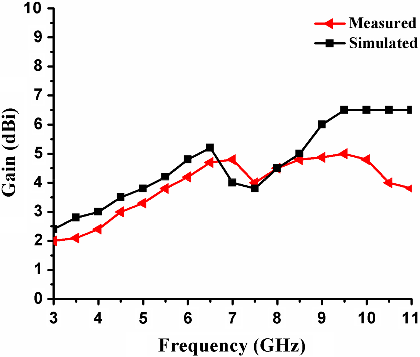
To characterize the radiation properties, normalized co-polar and cross-polar radiation patterns of the antenna at all the three orthogonal planes (XZ, YZ, and XY plane) at 3, 4.5, 7.4, and 9.6 GHz are shown in Fig. 8. The figure reveals that a relatively stable radiation pattern has been observed over the entire return loss bandwidth. The slight deviations, especially at the higher frequency end, are due to increased losses in the substrate and excitation of higher order modes. Since the facility of the anechoic chamber was unavailable, the radiation pattern and gain measurements were carried out in the indoor laboratory environment. As a result, the measurement was affected by the reflected fields from nearby scatters. Though all sorts of efforts were made to reduce these reflections, they cannot be completely removed. Figure 8 further reveals a relatively high cross-polarization level at higher frequencies, which may be explained as a result of orthogonal orientations of the antenna elements. Figure 9 presents the comparison of a measured and simulated peak gain of the prototype over the entire frequency range.

Fig. 8. Measured radiation patterns of the UWB-MIMO antenna at (a) 3 GHz, (b) 4.5 GHz, (c) 7.4 GHz, and (d) 9.6 GHz.

Fig. 9. Measured and simulated gain (dBi) of the antenna.
The gain of the proposed antenna has been measured using two antenna method. The simulated gain response is also plotted in the same figure for comparison. The figure reveals a peak gain of 4 dBi with a less than 3 dBi variation over the entire UWB band.
C) Diversity characteristics
The diversity performance of the proposed prototype is evaluated by analyzing some important parameters such as ECC, DG MEG ratio, and CCL.
1) ENVELOPE CORRELATION COEFFICIENT
It identifies the signal fading ability of the multi-antenna system and also measures how much the adjacent elements are isolated or correlated to each other in terms of S-parameters as well as radiation patterns. It can be represented as [Reference Hallbjorner19],
 $$\rho _c = \displaystyle{{{\left \vert {S_{ii}^ * S_{ij} + S_{jj}^ * S_{ji}} \right \vert} ^2} \over {\left \vert {\left( {1 - {\left \vert {S_{ii}} \right \vert} ^2 - {\left \vert {S_{ji}} \right \vert} ^2} \right)\left( {1 - {\left \vert {S_{jj}} \right \vert} ^2 - {\left \vert {S_{ij}} \right \vert} ^2} \right)} \right \vert}}, $$
 $$\rho _{eij} = \displaystyle{{{\left \vert {\int\!\!\!\int\limits_{4\pi} {\left[ {{\mathop G\limits^ \to} _1(\theta, \varphi ) * \mathop {G_2}\limits^ \to (\theta, \varphi )} \right]d\Omega}} \right \vert} ^2} \over {\int\!\!\!\int\limits_{4\pi} {{\left \vert {{\mathop G\limits^ \to} _1(\theta, \varphi )} \right \vert} ^2d\Omega \int\!\!\!\int\limits_{4\pi} {{\left \vert {{\mathop G\limits^ \to} _2(\theta, \varphi )} \right \vert} ^2d\Omega}}}}. $$
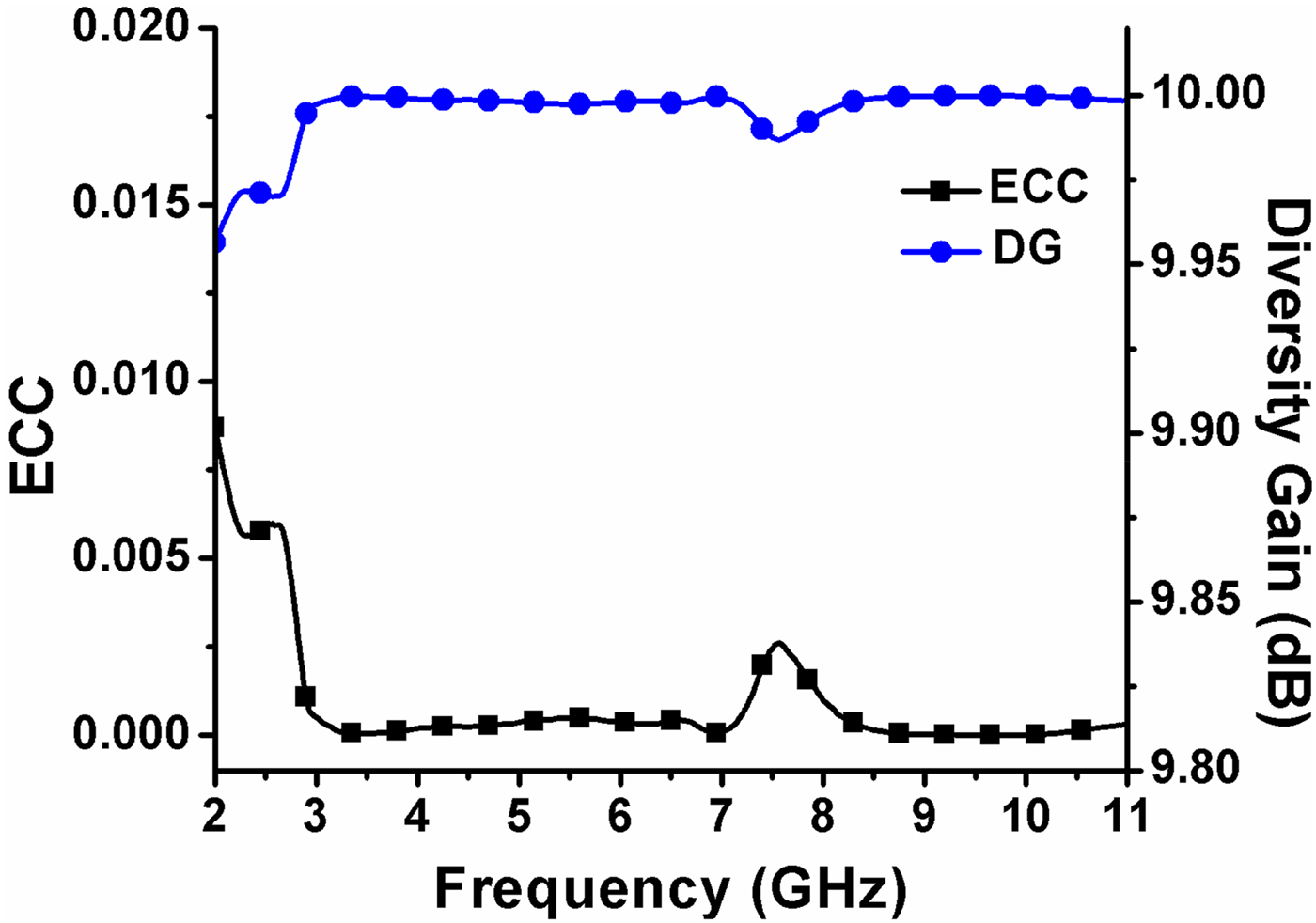
Computation of ECC in terms of S-parameters, using equation (1), assumes a lossless and single mode antenna whereas the computation of ECC in terms of the 3D radiation pattern, using equation (2), assumes uniform multipath environment [Reference Matin20]. Therefore ECC calculated using these two equations are generally different [Reference Matin20, Reference Jha and Sharma21]. Based on the measured S-parameters using equation (1), ECC of the antenna at different frequencies have been calculated and plotted in Fig. 10. It reveals that throughout the whole UWB range ECC < 0.003. Hence the proposed prototype satisfies the ECC criteria for a good diversity performance in a MIMO system [Reference Zhang, Lau, Sunesson and He22]. DG in dB can be obtained by using the relation [Reference Ko and Murch23]:
 $${\rm DG} = {\rm DGo} \cdot {\rm DF} \cdot K,$$
 $${\rm DF} = \sqrt {1 - \rho _c}. $$
For an ideal case DG ≈ 10.2 dB, which assumes correlation between the antennas as zero and ‘K’ is the branch power ratio (≈1) and can be determined by using [Reference Ko and Murch23],
 $$K = {\rm Min} ( \vert {\rm MEG1}/{\rm MEG2} \vert, \vert {\rm MEG2}/{\rm MEG1} \vert ).$$
It is observed from Fig. 10 that, the DG of the proposed antenna across UWB bandwidth approaches 10 dB. Based on equation (3), above ECC value corresponds to diversity gain 9.97 dB.

Fig. 10. Calculated ECC and DG in terms of measured S parameters.
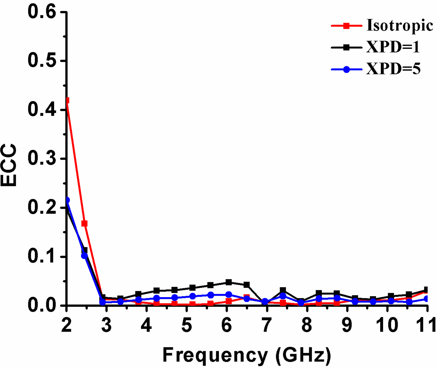
ECC, based on equation (2), can be obtained using commercial EM simulation tool and is plotted in Fig. 11 for isotropic (XPD = 0 dB), outdoor (XPD = 1 dB), and indoor (XPD = 5 dB) environments.

Fig. 11. ECC of the proposed UWB-MIMO antenna for isotropic (XPD = 0 dB), outdoor (XPD = 1 dB), and indoor (XPD = 5 dB) environments.
2) MEAN EFFECTIVE GAIN
It characterizes the diversity performance of the multiport antenna in a predefined wireless environment. It can be stated as the ratio of mean received power from the antenna to the mean incident power to the antenna along a route and can be represented as [Reference Taga24],
 $$\eqalign{{\rm ME}{\rm G}_n & \approx \displaystyle{{P_{rec}} \over {p_{inc}}} \cr & \approx \oint {\left[ {\displaystyle{{{\rm XPD} \cdot G_{\theta n} \cdot P_{\theta n} + (1 + {\rm XPD}) \cdot G_{\varphi n} \cdot P_{\varphi n}} \over {1 + {\rm XPD}}}} \right]} {\rm d}\Omega,}$$
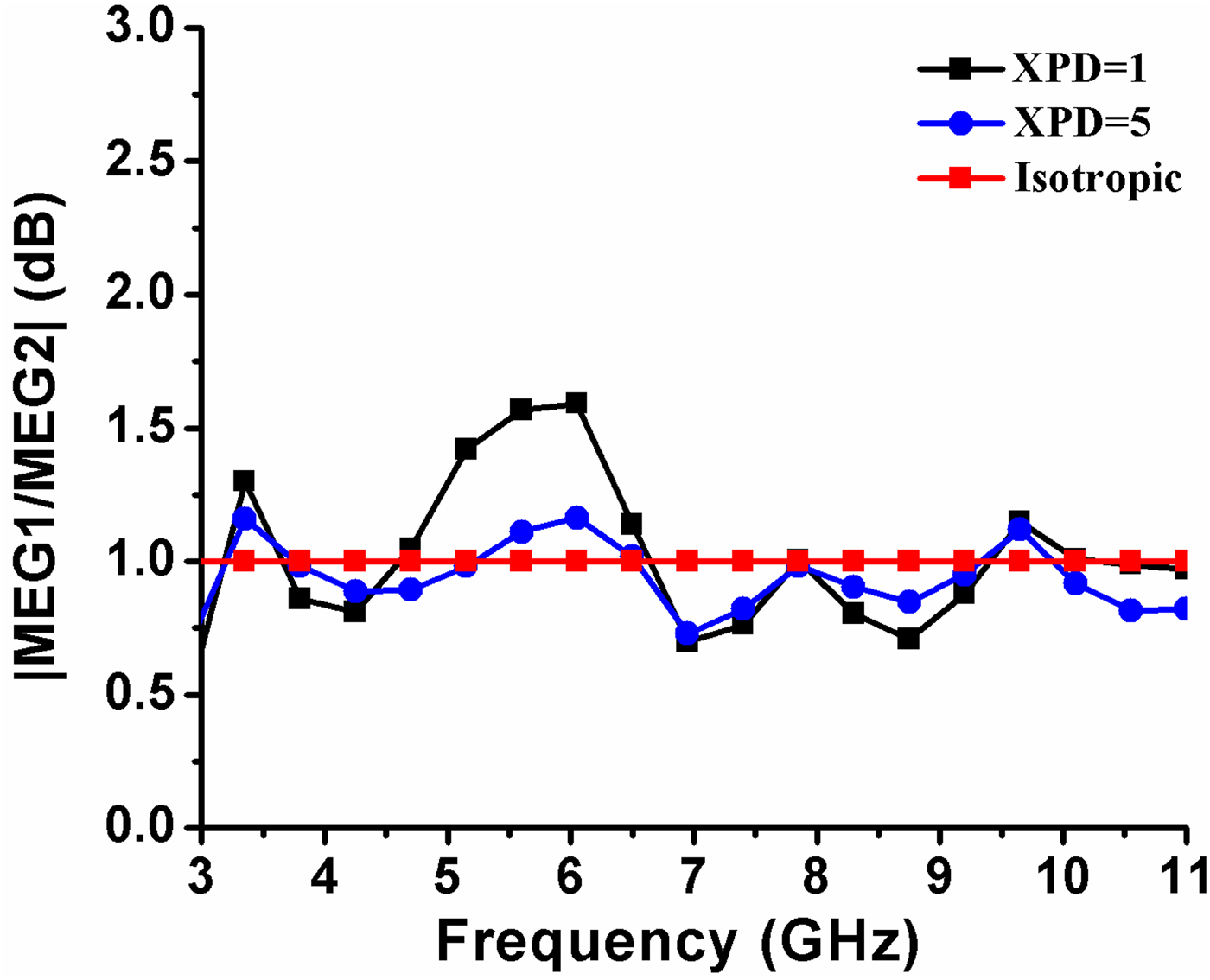
where, XPD is the cross polarization discrimination of the incident signals, G θ and G φ represents gain polarized components and P θ and P φ represent the channel model, and Ω is the solid angle. Like ECC, MEG of the antenna, based on equation (6) can also be found using commercial EM simulation tool and is plotted in Fig. 12 for Gaussian scenario(Gaussian distribution for elevation and uniform distribution for azimuth) with a mean elevation angle of vertical/horizontal polarized distributions m v = m H = 10° and standard deviation of vertical/horizontal polarized wave distributions σ v = σ H = 15° [Reference Ko and Murch23]. Three propagation models have been considered to compute the MEG, i.e., (i) Isotropic (XPD = 0 dB), (ii) Outdoor (XPD = 1 dB), and (iii) Indoor (XPD = 5 dB) environments. A good diversity performance is established when, it satisfies the criteria |MEGi/MEGj| ≅ 1 and should not exceed ±3 dB [Reference Ko and Murch23]. From Figs. 11 and 12, it can be concluded that the proposed antenna provides a good diversity characteristics and more suitable for the indoor application (XPD = 5 dB), e.g., WBAN/WPAN.

Fig. 12. MEG ratio of the proposed UWB-MIMO antenna for isotropic (XPD = 0 dB), outdoor (XPD = 1 dB), and indoor (XPD = 5 dB) environments.
3) CHANNEL CAPACITY LOSS
It is an essential parameter to realize the channel capacity of the MIMO system. In order to increase the channel capacity, CCL must be zero, which could not be possible due to the presence of correlation between the closely spaced antenna elements. CCL can be obtained from the measured S parameters for a multipath environment considering high SNR values using [Reference Zhou, Quan and Li25],
 $$C_{(loss)} = - \log _2\det (\psi ^R).$$
Here, ψ R is a 2 × 2 correlation matrix in terms of S parameters for a two-port MIMO system.
 $$\psi _{ii} = 1 - \left \vert {S_{ii}} \right \vert ^2 - \left \vert {S_{ij}} \right \vert ^2,$$
 $$\psi _{ij} = - (S_{ii}*S_{ij} + S_{ji} * S_{jj}).$$
The CCL of the antenna has been calculated using measured S-parameter values and is plotted in Fig. 13 with frequency. The figure reveals that the measured CCLs are less than 0.38 Bps/Hz over the entire UWB span, satisfying a good diversity performance as given in [Reference Zhou, Quan and Li25].

Fig. 13. Measured CCL of the proposed UWB-MIMO antenna.
IV. CONCLUSION
This paper proposes a compact low profile MIMO/diversity antenna for indoor UWB systems. The MIMO antenna exhibits a 10 dB return loss bandwidth from 2.9 to 11 GHz that covers the entire UWB frequency span with an isolation level greater than 20 dB. A value of ECC ≤ 0.003, CCL ≤ 0.38 Bps/Hz, and a ratio of MEG ≈ 1 (XPD = 5) have been observed throughout the UWB frequency span, satisfying a good diversity performance for the indoor system. A comparison of the characteristics of different reported UWB-MIMO antennas with the characteristics of the proposed UWB-MIMO antenna is presented in Table 1. It reveals that the proposed design is compact and has a good diversity performance.
Table 1. Comparison between proposed prototype and reported UWB-MIMO monopole antenna.
ACKNOWLEDGEMENT
The authors would like to thank DST, Government of INDIA for their instrumental support through FIST Project.
 Sonika Priyadarsini Biswal received her M.Tech in Electronics and Communication Engineering from Institute of Technical Education and Research, Bhubaneswar, India, in 2014 and B.Tech in Electronics and Telecommunication from College Of engineering Bhubaneswar, India, in 2012. She is currently pursuing her Ph.D. in the Department of Electronics Engineering, Indian Institute of Technology (ISM), Dhanbad, India. In her area of specialization, she is interested in Microwave Antennas and her recent research activities have focused on MIMO antenna design. She is a student member of IEEE.
 Sushrut Das received B.Sc., M.Sc., M.Tech, and Ph.D. degree in 1999, 2001, 2003, and 2007, respectively. He joined Indian Institute of Technology (Indian School of Mines), Dhanbad, India in 2007 where he is currently an Assistant Professor in the Department of Electronics Engineering. He has authored one book, Microwave Engineering (Oxford University press, 2014) and published several research papers in referred International Journals. He has received URSI (International Union of Radio Science) Young Scientist Award in Istanbul, Turkey. His research interest includes Microwave Antennas, Microwave passive structures, Wireless energy transfer, and energy harvesting. Dr. Das is a member of IEEE.