I. INTRODUCTION
Today using wireless communication technologies such as WLAN and GSM/UMTS/LTE-WWAN systems in laptops and other digital devices with wireless network access functions are very popular [Reference Shin, Hong and Choi1]. Universal serial bus (USB) dongle is a small terminal that can be connected to a computer. It has been developed as a wireless adapter designed to compensate for the insufficient bands of laptops and other digital devices. However, there is considerable challenge to realize a small internal multiband antenna design in such an USB dongle with a common volume of 22 × 55 × 9 mm3. Extensive research activities have been published toward the development of multiband antennas for wireless USB dongle applications [Reference Pazin and Yehuda2–Reference Wong, Wu and Su6], monopole antennas [Reference Yu and Choi3–Reference Park and Choi4], and planar inverted-F antennas [Reference Pazin and Yehuda2]. However, these complicated antennas cannot cover bandwidths broad enough for future communication requirements, especially for GSM 850/900/1800/1900/ UMTS 2100 and LTE700/2300/2500 bands.
In this letter, a hexa-band three-dimensional (3D)-internal monopole antenna for wireless USB dongle application is proposed. It has a simple structure and compact volume. The proposed antenna consists of two arms, a semi-circular monopole ended by three unit cells of meander-line and rectangular monopole with four unit cells of high-impedance wire (HIW) [Reference Safwat, Tretyakov and Raisanen7], each is responsible for certain bands of operation. The antenna satisfies −6 dB reflection coefficient which is sufficient for wireless broadband GSM (900/1800 MHz), (WiBro, 2.3–2.4 GHz), wireless local area network (WLAN, 2.4–2.485 and 5.15–5.825 GHz), world interoperability for microwave access (WiMAX, 2.5–2.7 GHz), and most of LTE bands and satellite digital multimedia broadcasting (S-DMB, 2.605–2.655 GHz) services. For portable wireless devices, the suitable antenna bandwidth is VSWR 3:1 as in [Reference Wong, Chang and Chen8–Reference Kim, Wang and Park11]. All simulations are carried out using the EM commercial simulator high-frequency structure simulator (HFSS) version 13.0, which is based on the finite-element numerical method.
II. PROPOSED DESIGN OF USB ANTENNA
The evolution of the proposed antenna is shown in Fig. 1. In step 1, shown in Fig. 1(a), the radiating patch is shaped as a semi-circular monopole with radius 10 mm to create a broad band that extends from 1.5 to 2.5 GHz [Reference Li, Zhang, Zheng, Feng and Iskander12–Reference Park, Kang and Sung17]. In step 2, shown in Fig. 1(b), a semi-circle slot with 1 mm width is etched in the patch to generate a resonant mode at 1.3 GHz. In step 3, shown in Fig. 1(c), a rectangular monopole is added to generate a resonant frequency at 1.1 GHz. To reduce this frequency and generate another resonant frequency, the monopole is replaced by four cells of HIW [Reference Safwat, Tretyakov and Raisanen7].

Fig. 1. The design procedure of the proposed antenna (a) step one, (b) step two, (c) step three, (d) step four in 2D layout, dashed lines indicate where the sheet needs to be bent to obtain the 3D version, (e) 3D layout geometry of the internal USB antenna, (f) 3D antenna with package, and (g) photo of the fabricated USB dongle with antenna.
The monopole resonant frequency is now 0.9 GHz and an additional resonant frequency appears at 5.5 GHz. In step 4, shown in Fig. 1(d), three meander unit cells with 1 mm strip width and separation are added to generate two resonant frequencies at 3 and 3.5 GHz. The performance after every the design step is shown in Fig. 2(a). All dimensions are shown in Table 1.

Fig. 2. The simulated |S 11| characteristics. (a) At different design steps and (b) effect of package size.
Table 1. The geometric dimensions of the proposed antenna (all dimensions in mm).

The proposed antenna occupies a volume of about 45 × 38 × 0.8 mm3. To fit an USB package, the antenna folded as shown in Fig. 1(e), hence the antenna volume is now 11 × 15 × 4 mm3, i.e. the reduction in the antenna volume is about 14% from the original antenna size. The folded antenna is mounted on a commercial FR4 substrate with thickness of 0.8 mm and relative permittivity (ε r ) of 4.7. The area and size, which serves the USB dongle circuit board as well, is 50 × 20 mm2. The folded antenna has almost the same behavior as the unfolded-one, as shown in Fig. 2(b). Finally, an USB package is added as a polyethylene material with dielectric constant 3.5, loss tangent tan δ = 0.02, area 45 × 20 mm2, thickness 0.5 mm, and different dongle height (4 and 6 mm) as shown in Fig. 1(f). The USB dongle is connected to the laptop ground plane through the USB connector interface that has size 5 × 8 mm2. The package affects the antenna reflection coefficient slightly as shown in Fig. 2(b) and decreases as the USB height is increased from 4 to 6 mm.
The surface current distributions at six operating frequencies, 0.9, 1.4, 1.8, 2.4, 3.5, and 5.2 GHz, are shown in Figs 3(a)–3(f), respectively. Two-dimensional (2D) plots are used to clarify the radiating element at each frequency. The monopole loaded with HIW radiates at 0.9 GHz (Fig. 3(a)) and 5.2 GHz (Fig. 3(f)), the meander line is responsible for radiation at 3.5 GHz (Fig. 3 (e)), and the slotted half-circled monopole is the primary source of radiation at 1.4, 1.8, and 2.4 GHz as shown in Figs 3(b)–3(d), respectively. At these frequencies some of the currents couple to the HIW monopole, which may reduce the radiation efficiency due to current cancellations.

Fig. 3. (a)–(e) The surface current densities for the proposed monopole antenna at 0.9, 1.4, 1.8, 2.4, 3.5, and 5.2 GHz, respectively.
III. RESULTS AND DISCUSSIONS
The prototype of the proposed antenna is fabricated by using photolithographic techniques on commercial FR-4 substrate. The antenna is fed by a 50-Ω coaxial cable as shown in Fig. 1(e). Measured and simulated |S 11| are depicted in Fig. 4 without the package and in Fig. 5 with the package. There is a good agreement between measured and simulated results in both antenna cases. Table 2 shows the simulated antennas parameters, efficiency, gain, and fractional bandwidth. The −6 dB bandwidth covers most of the LTE bands, GSM850/900, DCS1800, PCS1900, UMTS2100, Bluetooth 2400, WiMax (3500–5800), and WLAN 5200.

Fig. 4. Measured and simulated reflection coefficients of the proposed antenna.
Table 2. The parameters of the proposed antenna simulated and measured.

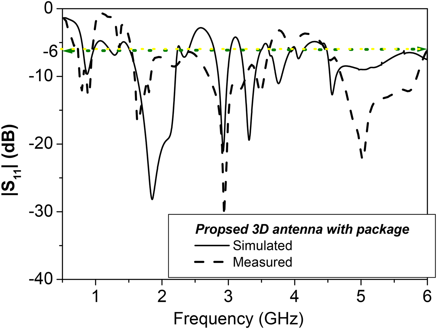
Figure 5 shows that the reflection coefficient is slightly distorted due to packaging by about 5 dB on average especially at high frequency but still covers the required resonant frequencies. Radiation efficiency is measured over the operating bands using the Wheeler cap method [Reference Johnston and Mc Rory18–Reference Pozar and Kaufman20] and it is shown in Fig. 6, which also shows the simulated one. The average radiation efficiency is around 70% over the operating bands.

Fig. 5. Measured and simulated reflection coefficients of the proposed antenna with package.

Fig. 6. Measured and simulated radiation efficiency over the operating bands.
Measured radiation patterns in the XY- and YZ-planes, shown in Fig. 1(d), at six resonant frequencies, 0.9, 1.4, 1.8, 2.4, 3.5, and 5.2 GHz, are shown in Table 3, respectively. For almost all the frequency bands, the normalized co-polarized patterns show near omni-directional radiations and their corresponding cross-polarized patterns exhibit monopole-like. The average difference between the co and cross levels in the main plane is higher than 10 dBi. Some discrepancy appears at certain frequencies that may be attributed to the inadequate size of the absorbers in addition to poor isolation.
Table 3. Measured radiation pattern E θ (– –) and E Ф (—) at 0.9, 1.8, 2.4, 3, 3.5 and 5.2 GHz, respectively.

The radiation tends to be broadside similar to those obtained for conventional internal patch antennas for mobile phone applications and it follows the current distribution shown in Fig. 3. At 0.9 GHz, the radiation pattern corresponds to a monopole in the XZ- and XY-planes, from 1.5 to 2.5 GHz which corresponds to a monopole in the XZ-plane, while at 3.5 GHz the radiation corresponds to a meander monopole in the XZ-plane, and at 5.2 GHz it corresponds to the HIW monopole in the YZ-plane. The antenna characteristics such as efficiency, gain and |S 11|<−6 dB impedance bandwidth are shown in Table 2. The antenna's radiation efficiency is also studied by using the Wheeler cap method [Reference Johnston and Mc Rory18–Reference Pozar and Kaufman20] at the resonant frequencies as shown in Table 2. Results indicate that the size reduction comes at the expense of the radiation efficiency, which reduces by 5–10% at different operating resonant frequencies.
Table 4 shows a brief comparison between our design and the previous published papers. The great advantage of this design is that it is easy to extend the proposed design to cover multi-services and to design 3D monopole antenna with independent tuning, easier fabrication, and reduced design complexity.
Table 4. Brief comparison of the proposed antenna with published papers.

IV. CONCLUSION
In this paper, a 3D monopole was designed to operate at many wireless communications bands GSM, UMTS, WCDMA, Bluetooth, ISM, 802.11b/g, LTE, as well as 802.11a/n. The proposed antenna has a simple structure and narrow ground plane, and it is small enough to fit in an USB dongle. It consists of two connected monopoles. One has a slotted semicircular patch terminated by three meander line unit cells, while the other is a bent monopole that has four HIW unit cells. The antenna was successfully designed, implemented, and measured with average radiation efficiency about 70% over the operating bands. The gain varies with frequency with average 3.8 dBi. The antenna's radiation is nearly omni-directional at the different resonant frequencies. The proposed antenna is a good candidate for USB dongle applications.
ACKNOWLEDGEMENTS
This work was supported by the Information Technology Industry Development Agency, Information Technology Academia Collaboration (ITIDA-ITAC), Ministry of Communications, Egypt.
 Dalia M. Elsheakh received the B.Sc., M.Sc. and Ph.D. degrees from Ain Shams University in 1998, 2005 and 2010, respectively. Her M.S. thesis was on the design of microstrip PIFA antennas for mobile handsets. Her Ph.D. was entitled, “Electromagnetic Band-Gap (EBG) Structure for Microstrip Antenna Systems (Analysis and Design).” From 2008 to 2009, she was Assistant Researcher at the Hawaii Center for Advanced Communications, College of Engineering, Hawaii University at Manoa. She has published 32 papers in peer-refereed journals and 30 papers in international conferences in the area of microstrip antenna design. Her current research interests are in microstrip antennas' theory and metamaterials design and electromagnetic wave propagation. She participates in many research projects at the national and international levels such as the Egypt-NSF-USA joint funds program and the European Committee Programs FP7 program, STDF, and ITIDA-ITAC.
 Amr M. E. Safwat received the B.Sc. and M.Sc. degrees from Ain Shams University in 1993 and 1997, respectively, and the Ph.D. degree from the University of Maryland at College Park, in 2001, all in Electrical Engineering. From August 2001 to August 2002, he was with Cascade Microtech Inc. In August 2002, he joined the Electronics and Communication Engineering Department, Ain Shams University, where he is currently an Associate Professor. He has held visiting professor positions at the Otto-Von-Guericke University, Magdeburg, Germany (September 04–November 04), the Institut National Polytechnique de Grenoble, Grenoble, France (September 05–November 05), and the Radio Laboratory and MilliLab, Helsinki University of Technology, Finland. His research interests include microwave passive planar structures and microwave photonics. Dr. Safwat was awarded the Egyptian encouragement state prize for Engineering Sciences in 2008.