Introduction
Metasurfaces (MTSs) are the periodic sub-wavelength planar metal or dielectric patches, which are used in plenty of applications due to their potentials to control the electromagnetic (EM) waves. This controlling property of EM waves is used in beam tilting, beam shaping, frequency reconfigurability, and polarization reconfigurability, etc. MTSs are designed with ultra-thin thickness to reduce the losses in wave propagation direction [Reference Chen, Taylor and Yu1,Reference Holloway, Kuester, Gordon, O'Hara, Booth and Smith2]. The MTSs have the potential to convert a linearly polarized (LP) wave into circularly polarized (CP) wave, which are reported in the literature [Reference Zhu, Cheung, Chung and Yuk3–Reference Cabedo-Fabres, Antonino-Daviu, Valero-Nogueira and Bataller10]. Many techniques are used along with LP to CP conversion [Reference Zhu, Cheung, Chung and Yuk3] to enhance the antenna property like polarization reconfigurability [Reference Zhu, Cheung, Liu and Yuk4], radar cross-section(RCS) reduction [Reference Kandasamy, Majumder, Mukherjee and Ray5], frequency reconfigurability [Reference Ni, Chen, Zhang and Wu6]. In [Reference Zhu, Cheung, Chung and Yuk3–Reference Ni, Chen, Zhang and Wu6], equivalent circuit model is used to analyze MTS, but it is very challenging to design MTS based on certain circuit topology. In [Reference Zhang and Dong7], the RCS is reduced along with gain enhancement. Wide axial ratio bandwidth is achieved using rectangular ring-based MTS [Reference Nasimuddin, Chen and Qing8] and rectangular patch-based low profile polarization-dependent MTS(PDMTS) [Reference Wu, Li, Li and Chen9]. These MTSs have difficulty in analyzing and excitation of modes which contribute to radiation performance.
Characteristic mode analysis (CMA) is used to analyze MTSs with mode behavior and its excitation. Many recent designs are analyzed using modal analysis such as wire antenna, planar monopole, mobile chassis [Reference Cabedo-Fabres, Antonino-Daviu, Valero-Nogueira and Bataller10,Reference Antonino-Daviu, Cabedo-Fabrés, Sonkki, MohamedHicho and Ferrando-Bataller11], metal- dielectric structure [Reference Rabah, Seetharamdoo, Berbineau and De Lustrac12], and magneto-dielectric arbitrary-shaped patch antennas [Reference HRabah, Seetharamdoo and Berbineau13]. Method of moment (MOM)-based analysis is used to find external resonances of conducting body [Reference TMiers and KLau14]. In addition, modal analysis is used to design mobile handset antennas [Reference Li and Shi15], wideband multiple input multiple output antennas [Reference Deng, Feng and VHum16]. Also, CMA is used to design wideband MTS antennas in [Reference HLin and Chen17–Reference Luo, Chen and Ma19]. A dual-band MTS antenna is analyzed using CMA in [Reference Li and Chen20]. The above discussed methods gives a deep understanding of CMA of single and multi-layered medium but limited to LP. Some of the CP antennas are analyzed using CMA, which are reported in the literature [Reference Chen and Wang21–Reference HTran, Nguyen-Trong and MAbbosh25]. A broadband CP slot monopole antenna and a wideband MTS CP antenna is designed using CMA in [Reference HTran, Nguyen-Trong and MAbbosh25,Reference Zhao and Wang26]. These antennas are limited to only CP application. Nowadays stealth technology requires low RCS antennas for future military applications in order to reduce the visibility of device. So it is very much essential to design CP antennas with RCS reduction capability.
Many techniques are presented in the literature to reduce in-band and out-band RCS of antennas using absorbing materials [Reference Pan, Huang, Chen, Ma, Hu and Luo27], EBG surface [Reference Xu, Wang, Chen, Zhang and Li28,Reference Jia, Liu, Wang, Li and Gong29], fence-like arrangement of AMCs [Reference Zhao, Cao, Gao, Yao, Liu, Li and Li30], and energy cancelation methods [Reference Zhao, Gao, Cao, Liu, Xu, Liu and Cong31]. In most of the cases, it is difficult to use absorbing materials (losses in metallic patches) and scattering method for in-band RCS reduction. In [Reference Wu, Su, Li and Su32], out-band RCS reduction is achieved using CMA by shifting the scattering modes. Recently in [Reference Xu, Wang, Chen, Zhang and Li28], CM method is used to reduce the in-band RCS of LP slot antenna. The present work focuses toward the design of a low profile MTS CP antenna using modal analysis with RCS reduction capability.
In this paper, a low profile PDMTS CP antenna analyzed using CMA with in-band RCS reduction capability is presented. The proposed PDMTS is investigated using a source-free CMA to convert LP wave to CP wave. The PDMTS produces two orthogonal degenerate modes and it is excited with LP slot antenna to show its polarization conversion capability. The absorptivity property of PDMTS is utilized to reduce the in-band RCS of the proposed antenna. The in-band RCS reduction performance of 30.2 dB is obtained with respect to slot antenna. Section “CMA of PDMTS” provides CMA of PDMTS. The PDMTS CP antenna geometry and its principle of operation is presented in section “CP antenna design using PDMTS”. The in-band RCS reduction is discussed in section “RCS reduction of the proposed antenna”. The simulated and measured results are compared in section “Experimental results and discussion” followed by conclusion in section “Conclusion”.
CMA of PDMTS
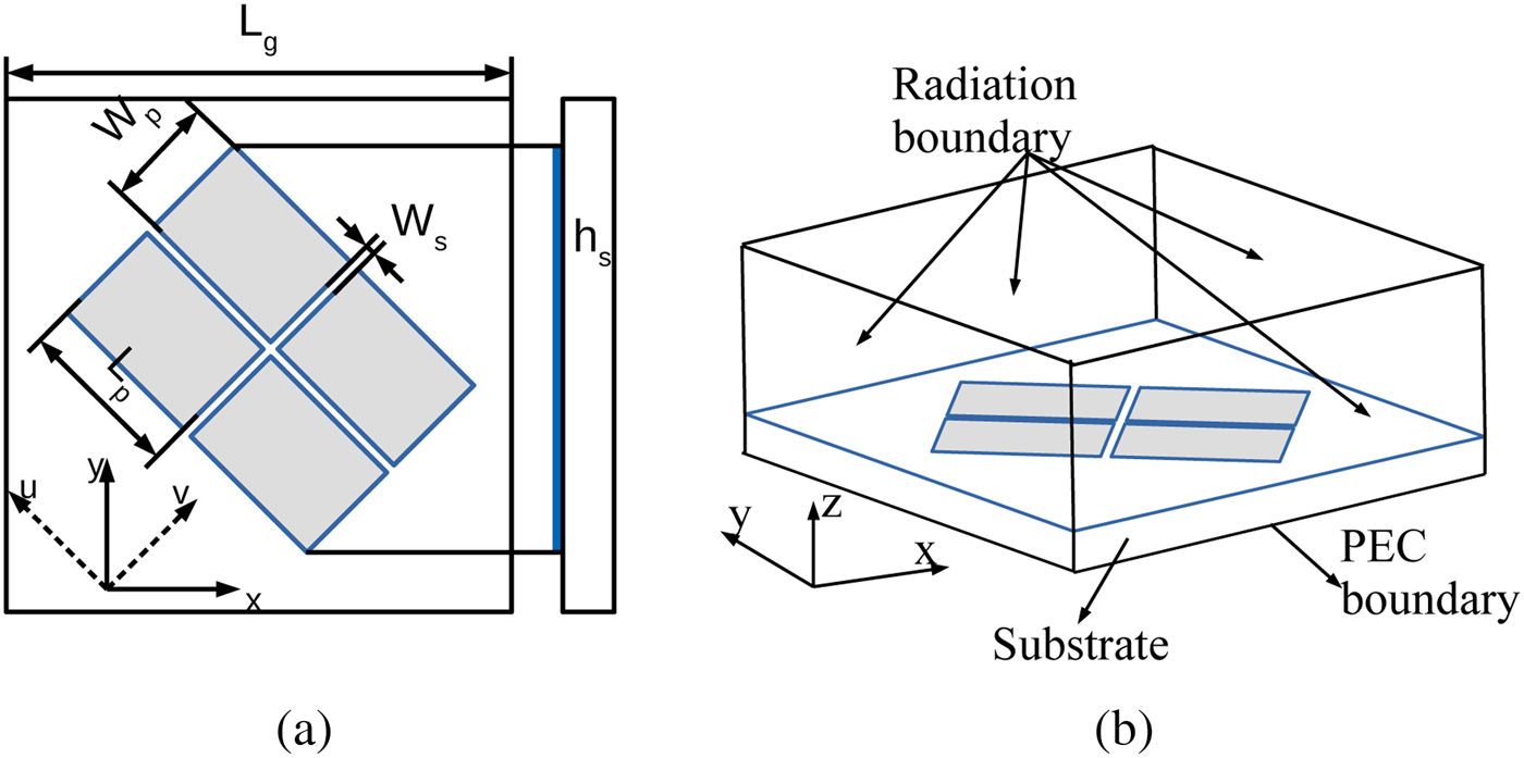
The rectangular patch-based PDMTS is shown in Fig. 1(a). The PDMTS is etched on top of roger RO4003C substrate ( $\epsilon _r=3.38$,
  $\tan \delta =0.0027$ and height
  $ {h_s}=3.454\,{\rm mm}$) and it is oriented
  $45^{\circ }$ with respect to xy plane. The PDMTS is analyzed using a MOM-based CMA tool in CST MWS. The CMA results of PDMTS is obtained with PEC boundary applied in
  $-z$ direction with all other sides as open boundaries as shown in Fig. 1(b).

Fig. 1. (a) Geometry of the proposed PDMTS. (b) Open radiation boundary set up with  $-Z$ direction as PEC.
  $L_g=27\,{\rm mm}$,
  $L_p=8.5\,{\rm mm}$,
  $W_p=6\,{\rm mm}$,
  $W_s=0.3\,{\rm mm}$,
  $h_s=3.454\,{\rm mm}$.
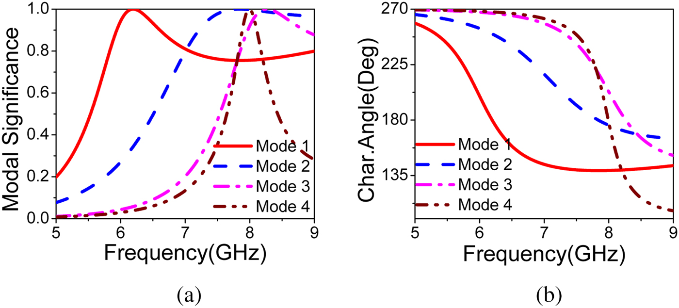
In characteristic mode (CM) theory, the generalized eigen value equation is given by,  $X\vec {J_n}=\lambda _n R \vec {J_n}$ where
  $\lambda _n$ is the eigen value. The eigen value reveals the resonant behavior of each mode. The modal significance (
 ${\rm MS}=1/(1+\lambda _n)$) and characteristic angle (
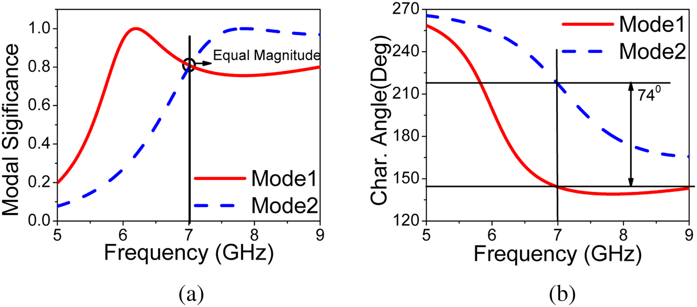
 ${\rm CA}=180^{\circ }-\lambda _n$) are the other two parameters, which effectively determine the radiation performance of each mode. The MS helps to distinguish between higher order CMs from fundamental CM by transforming eigen values to a smaller range [0,1]. The PDMTS patches are meshed and electrical currents are solved to get the modal behavior of PDMTS. The MS and CA of first four modes are shown in Fig. 2. In all CMA results, J1 to J4 represent the first CM to fourth CM. The first two modes have same magnitude and phase difference of
  $74^{\circ }$ at 7.02 GHz as shown in Fig. 3. Even though the phase shift between two modes is less than
  $90^{\circ }$ before feed excitation, circular polarization can be achieved satisfactorily after feed excitation [Reference Yang, Liu and Gong18].

Fig. 2. Simulated modal significance and characteristic angle of first four modes(J1–J4) of PDMTS.

Fig. 3. Simulated modal significance and characteristic angle of first two modes(J1, J2) of PDMTS.
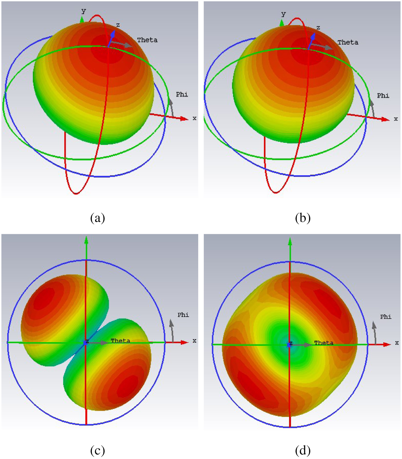
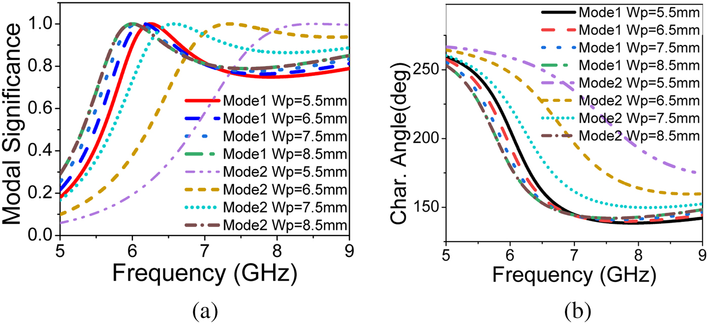
The modal currents of first four modes at 7.02 GHz are shown in Fig. 4. It is observed that all the modal currents of J1 are in-phase over the MTS in u direction and all J2 modal currents are in-phase over the MTS in v direction. J1 and J2 are the pair of orthogonal modes which are responsible for circular polarization. J3 and J4 are the higher order modes which are opposite current distribution about u and v axes. The modal radiation patterns of first four modes at 7.02 GHz are shown in Fig. 5. The first two modes are well radiated in bore-sight direction and orthogonal to each other, but higher order modes have radiation null at bore-sight direction. This analysis suggests that the first two modes are orthogonal and have an excellent in-phase current distribution with good broadside radiation performance. Excitation of mode J1 and mode J2 gives circular polarization with good broadside radiation pattern. The parametric study of characteristic modes is shown in Figs. 6 and 7, it is observed that the effect of  $W_p$ on the modes is significant. If the parameter
  $W_p$ increases, resonance shifts to lower frequency due to increase in the electrical size of the MTS. The phase shift between first two modes can be optimized using parameter
  $W_p$.
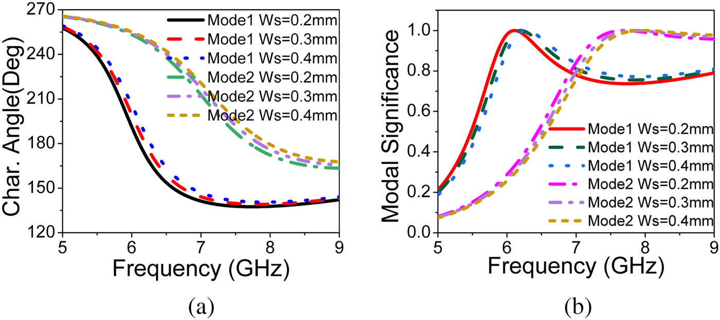
  $W_s$ decides coupling between patches, increasing the value of
  $W_s$ shifts the resonance to higher frequency. The parametric study of CMA helps us to optimize the modal behavior.
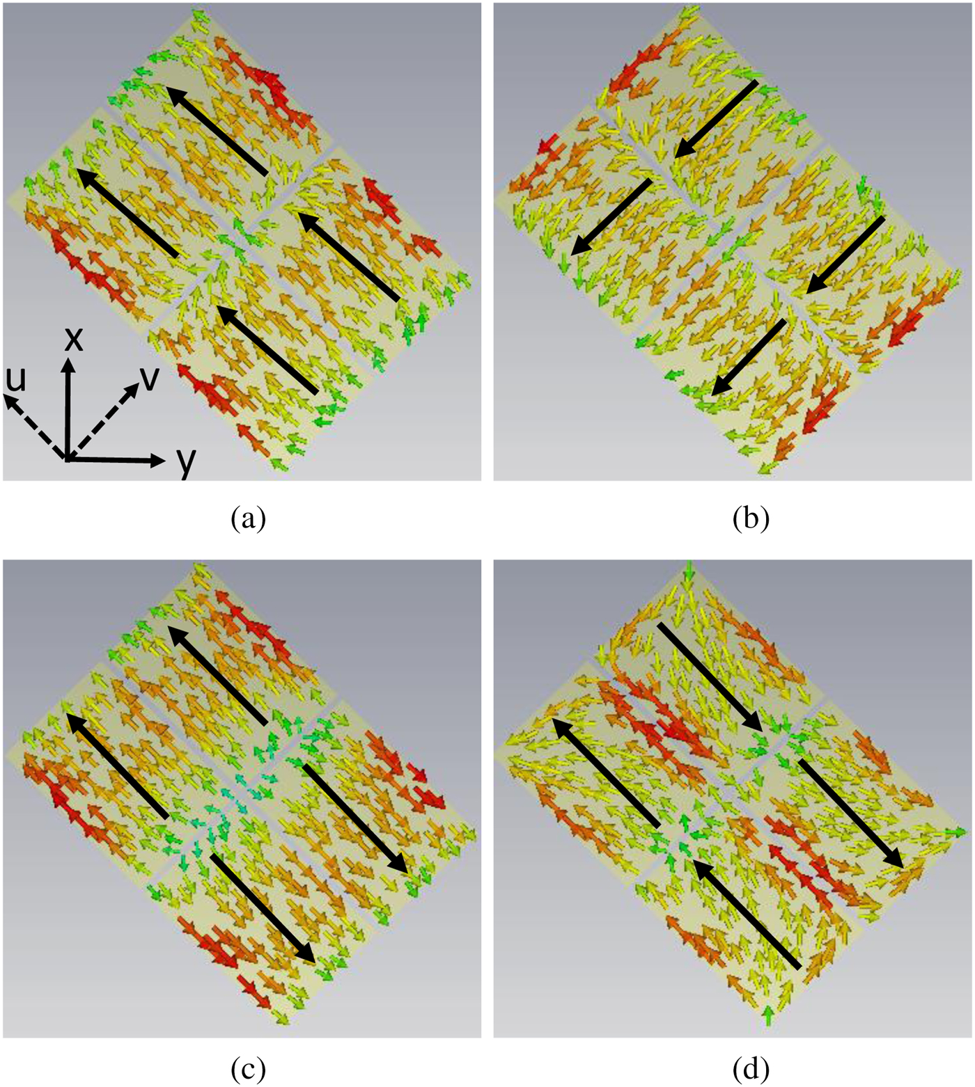
Fig. 4. Simulated modal current distribution of PDMTS. (a) J1, (b) J2, (c) J3, (d) J4.

Fig. 5. Simulated modal radiation pattern of PDMTS. (a) J1, (b) J2, (c) J3, (d) J4.

Fig. 6. Effect of  $W_p$ on simulated (a) modal significance and (b) characteristic angle.

Fig. 7. Effect of  $W_s$ on simulated (a) modal significance and (b) characteristic angle.
CP antenna design using PDMTS
The PDMTS analyzed using CMA method is loaded on slot antenna to design CP antenna. The proposed CP antenna consists of PDMTS (SS $'$), slot antenna (GG
 $'$), and microstrip feed line (FF
 $'$) as shown in Fig. 8. The slot antenna is designed using Rogers RO4003 substrate (
 $\epsilon _r = 3.38$,
  $\tan \delta = 0.0027$) witha thickness of
  $h_a = 0.508$ mm. The 50Ω microstrip feed line is printed on the top surface of the substrate and the slot is etched on its bottom surface. The optimized dimensions of slot antenna are
  $L_f=11.65$ mm,
  $W_f=1.5$ mm, and
  $W_{fl}=1.1$ mm. The PDMTS is loaded on the slot antenna as shown in Fig. 8(a) and bottom side is in direct contact with microstrip feed line without any air gap as shown in Fig. 8(b). The PDMTS, feed line, and slot are aligned at the center of xy plane. Since the PDMTS is oriented
  $45^{\circ }$ with respect to xy plane, the direction of modes J1 and J2 of PDMTS are in-phase with electric field component in u (Eu) and v direction (Ev) of the slot antenna. This enables the slot antenna to efficiently couple the PDMTS and produces right-hand CP (RHCP) wave. In order to get left-hand CP (LHCP) wave, the PDMTS should be placed on the other diagonal (v direction) of the substrate with respect to xy plane. It is observed that surface current distribution on PDMTS at different instant of time, RHCPis obtained in
  $+z$-direction as shown in Fig. 9.
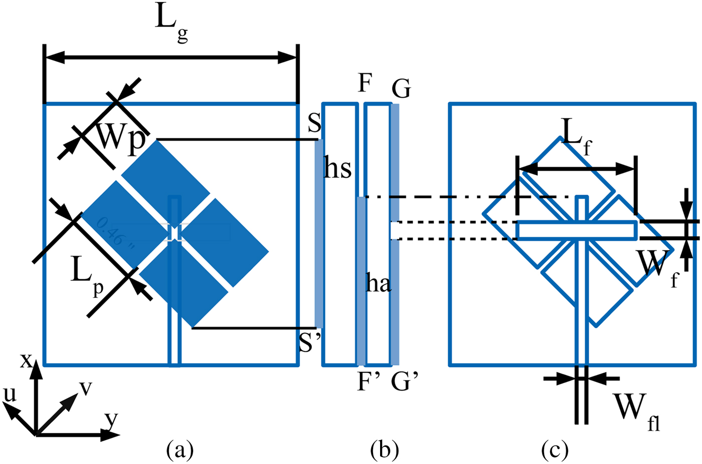
Fig. 8. Proposed antenna structure: (a) front view, (b) side view, (c) back view.
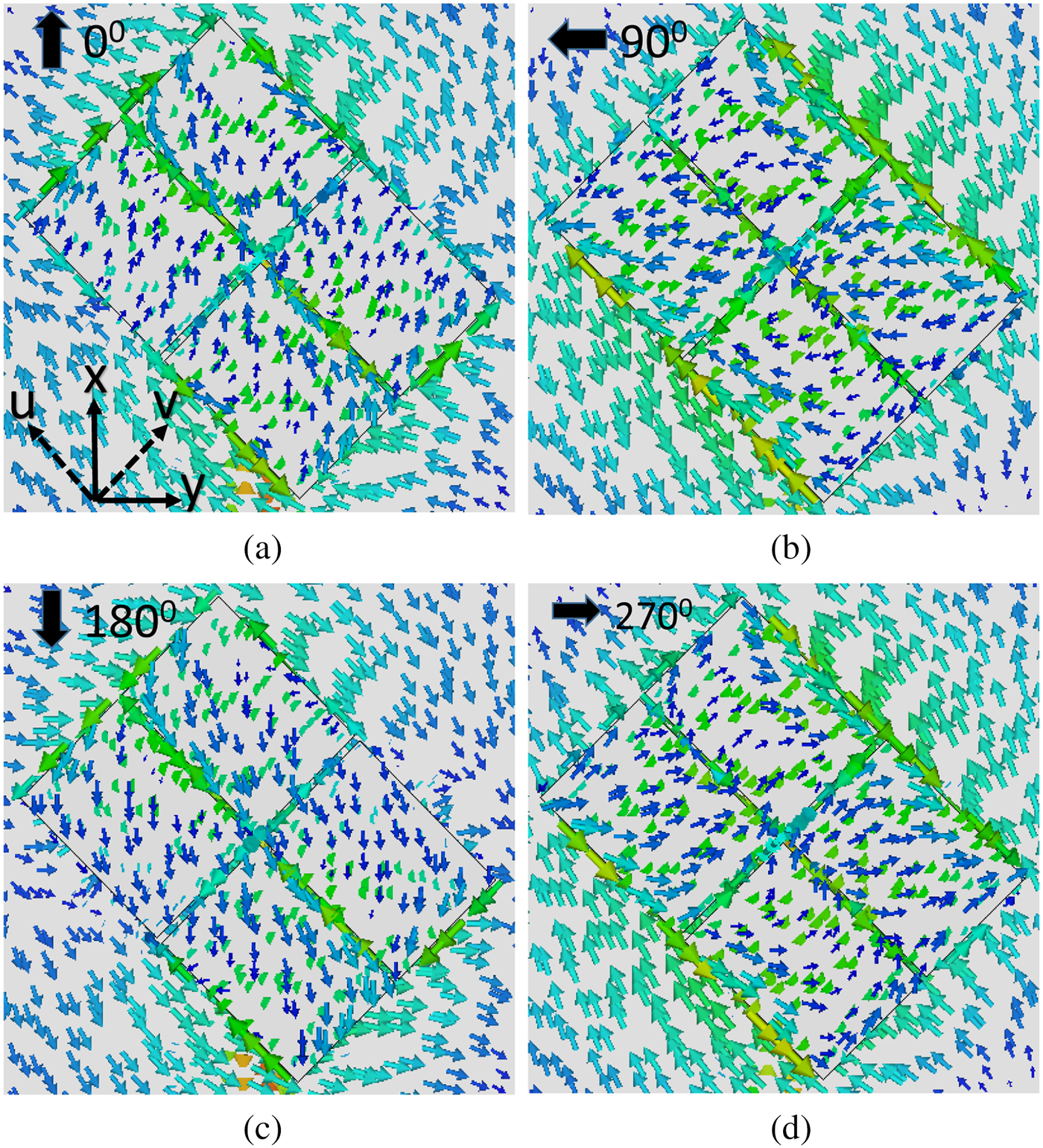
Fig. 9. Simulated surface current distribution at different time instant: (a) t = 0, (b)  $t=T/4$, (c)
  $t=T/2$, (d)
  $t=3T/4$.
The parametric study of PDMTS loaded slot antenna using full-wave analysis (FWA) is shown in Figs. 10 and 11. The most significant parameters are  $L_f$ and
  $W_f$, which give variation in the impedance bandwidth but not on axial ratio. As shown in the figure, increasing
  $L_f$ shifts the resonance to lower frequency and splits the mode into degenerating modes. By decreasing
  $L_f$, the mode shifts to higher frequency and also impedance matching degrades. Even though the modes of PDMTS analyzed using CMA are resonating at 7.02 GHz before excitation, due to the length of feeding slot, the resonance of CP antenna shifts to lower frequency after excitation. The MTS mode and slot mode are combined to give wider impedance bandwidth.
  $W_f$ does not affect much on the resonance frequency but it improves the impedance matching. By optimizing the parameters
  $L_f$ and
  $W_f$, good impedance bandwidth can be achieved.
  $W_p$ is the parameter which affects axial ratio significantly because of change in electrical dimension of MTS.
  $W_s$ is also helpful to optimize the axial ratio and impedance bandwidth. The CMA results are well in agreement with full wave analysis (FWA) as shown in the parametric study. Finally, the
  $L_f$ and
  $W_f$ are mainly contributing for impedance matching, while
  $W_p$ and
  $W_s$ help to optimize the axial ratio.
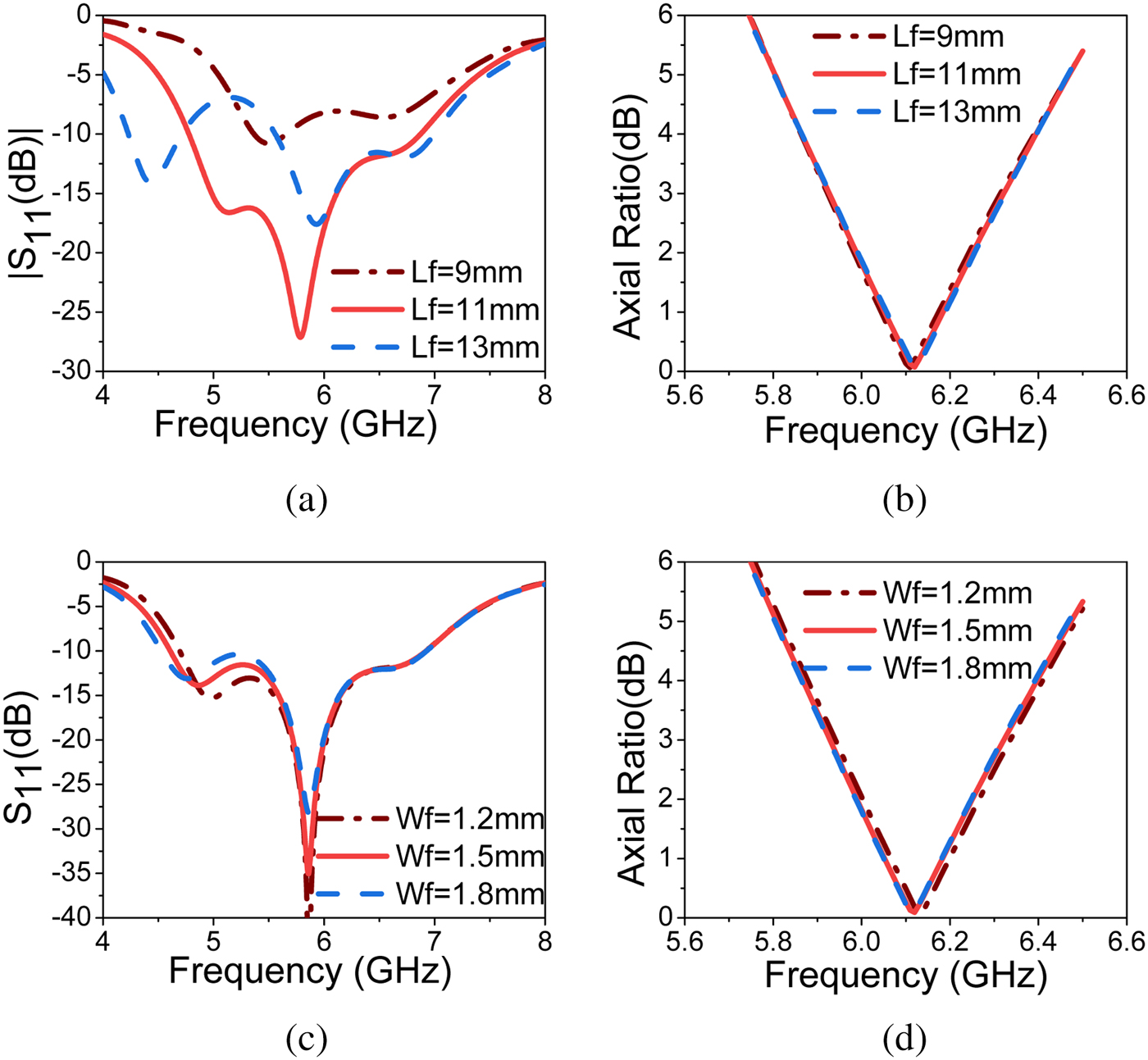
Fig. 10. Effect of  $L_f$ and
  $W_f$ on simulated
  $S_{11}$ and axial ratio (a and b)
  $L_f$, (c and d)
  $W_f$.
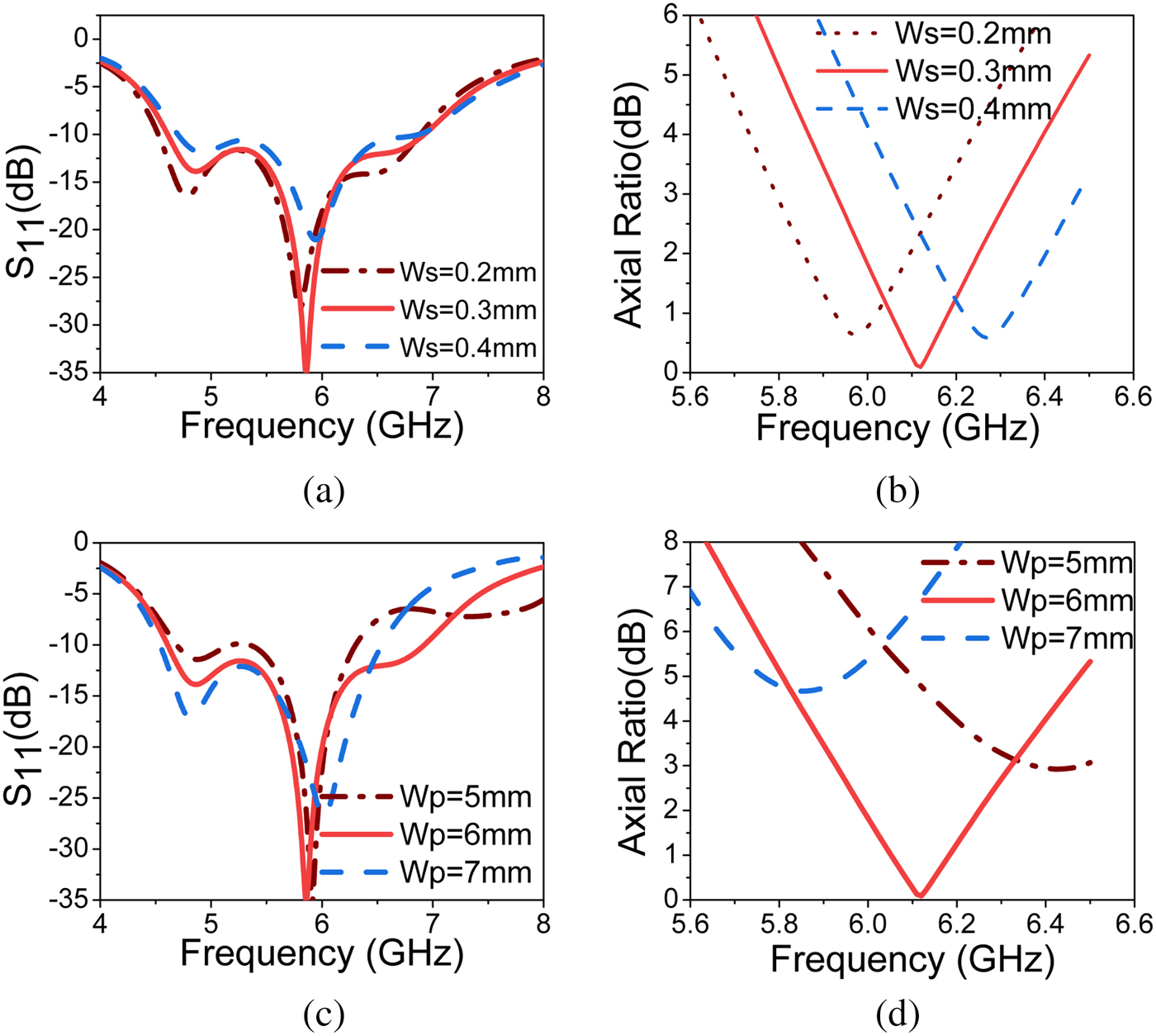
Fig. 11. Effect of  $W_s$ and
  $W_p$ on simulated
  $S_{11}$ and axial ratio (a and b),
  $W_s$ (c and d)
  $W_p$.
RCS reduction of the proposed antenna
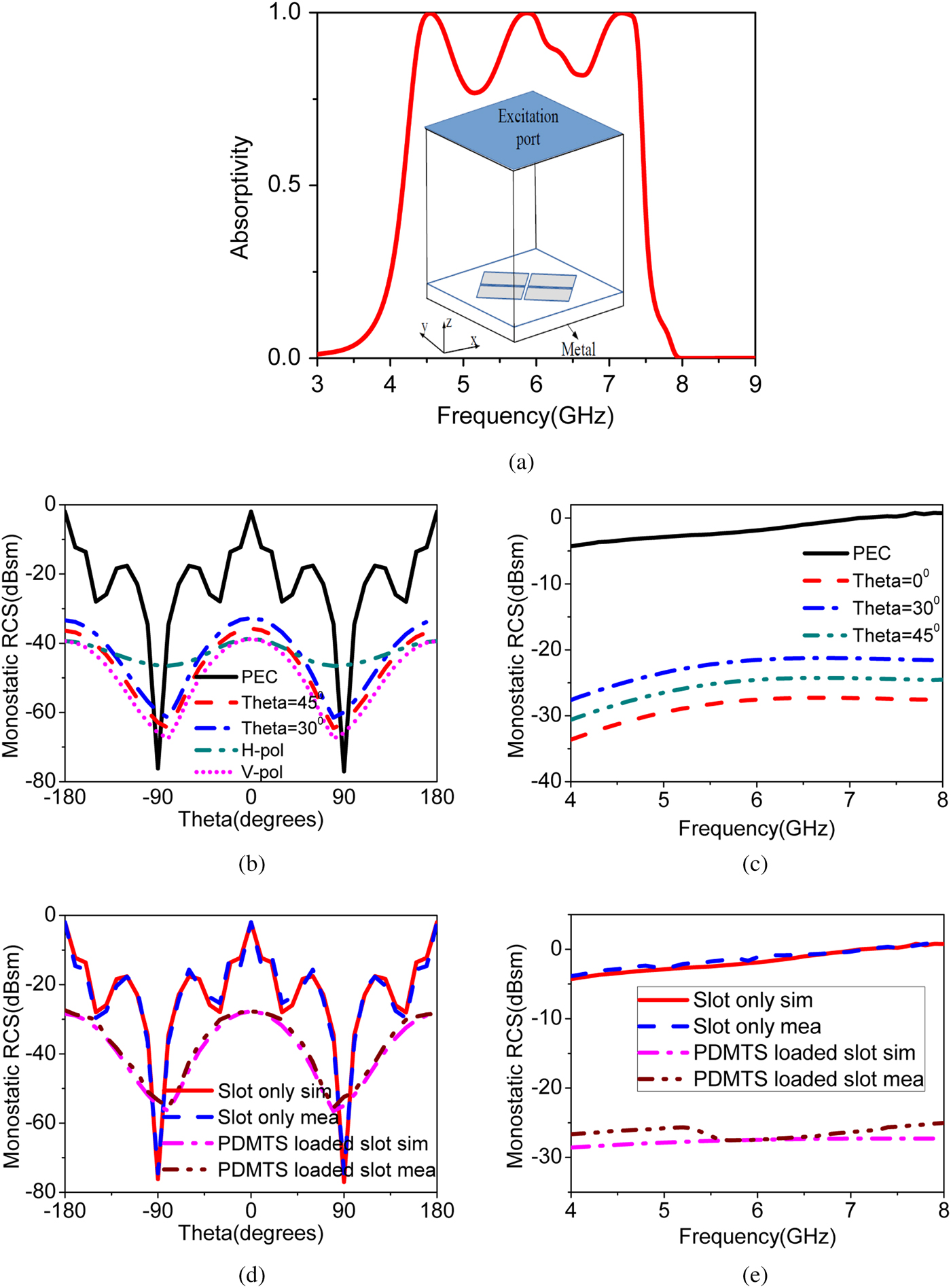
In stealth application like radar, antenna is also considered as a potential reflector of the overall system. In the proposed antenna without PDMTS loading, the slot acts as a primary source antenna with poor RCS performance. The MTS is absorbing the maximal incident energy and reduces the RCS. Two-dimensional periodic arrangement of sub-wavelength patches act as a absorbing medium. The simulation is carried out to find the absorptivity of the proposed metal backed MTS at the resonance frequency. The absorptivity is calculated from the reflection coefficient for a plane wave incident with the MTS. The absorptivity curve is shown in Fig. 12(a). The simulation set-up is shown in the subset of the same figure. The absorptivity is calculated using  $A=1 - \vert S_{11} \vert ^2$, the proposed PDMTS covered slot antenna gives the absorptivity of 95
 $\%$. When absorptivity value is nearly 100
 $\%$, the material acts as an absorber. Absorbers act as RCS reduction materials [Reference Kandasamy, Majumder, Mukherjee and Ray5,Reference Zhang33–Reference Ghosh36].

Fig. 12. (a) Simulated absorptivity magnitude of metal backed PDMTS. (b) Simulated monostatic RCS variation of PDMTS loaded slot antenna over oblique incidence. (c) Simulated frequency response of the monostatic RCS versus oblique incidence. (d) Simulated and measured monostatic RCS versus angle at 5.86 GHz for y polarized wave. (e) Simulated and measured frequency response for y polarized wave at broadside direction.
To observe the in-band RCS reduction capability of PDMTS loaded slot antenna, simulations and measurements are carried out for plane wave incident with different incident angles. The proposed antenna achieves monostatic RCS reduction of  $-32.2$ dBsm for y polarized wave at the resonance frequency of 5.86 GHz. The variation of monostatic RCS with respect to different incident angle is shown in Fig. 12(b). The observed monostatic RCS of slot antenna without PDMTS is
  $-2\,{\rm dBsm}$ at its resonant frequency. It shows that there is a remarkable RCS reduction of
  $-30.2$ dBsm is achieved with loading of PDMTS on the slot antenna. The PEC is the standard EM wave reflector. To evaluate the RCS reduction performance of the proposed PDMTS, the RCS of PEC is compared with the PDMTS. The RCS performance of the PDMTS loaded slot is compared with the slot antenna to show the RCS reduction capability of the PDMTS [Reference Zhao, Cao, Gao, Yao, Liu, Li and Li30–Reference Wu, Su, Li and Su32]. The simulated RCS frequency response of PDMTS loaded slot antenna with different incident angles is shown in Fig. 12(c). It is observed that the frequency response shows nearly
  $-28\,{\rm dBsm}$ RCS reduction over the entire impedance bandwidth. The monostatic RCS of the proposed antenna is weakened with respect to oblique incidence over the in-band frequency. This is due to an increase in the reflectivity property of MTS with oblique incidence. The simulated and measured results of monostatic RCS for y polarized wave are shown in Figs. 12(d) and 12(e). The measured results are in well agreement with the simulated results.
Experimental results and discussion
The proposed prototype of the fabricated antenna is shown in Fig. 13. The comparison between the simulated and measured results of impedance bandwidth, axial ratio bandwidth, and gain are shown in Fig. 14. The simulated and measured impedance bandwidth  $(\vert S_{11} \vert < -10\,{\rm dB})$ is shown in Fig. 14(a). The simulated impedance bandwidth of 2.31 GHz (39.42
 $\%$) from 4.61 to 6.92 GHz and 3 dB axial ratio bandwidth of 0.39 GHz (6.72
 $\%$) from 5.92 to 6.31 GHz is achieved. The measured impedance bandwidth of 1.575 GHz (29.11
 $\%$) from 4.96 to 6.535 GHz and 3 dB axial ratio bandwidth of 0.49 GHz (9.05
 $\%$) from 5.83 to 6.32 GHz is achieved. The proposed PDMTS loaded slot antenna achieves a measured monostatic RCS value of
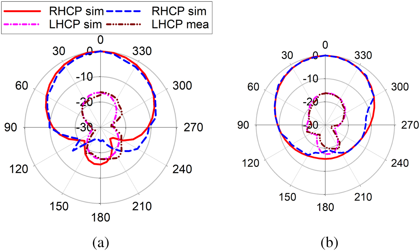
  $-23.2$ dBsm. The simulated and measured gain of the antenna is shown in Fig. 14(b). The measured bore-sight gain of 6.34 dB is achieved at the center frequency. There isa 0.5 dB gain variation in the entire axial ratio bandwidth because of small fabrication errors and SMA connector losses. The simulated and measured radiation patterns at two different frequencies in xz and yz planes are shown in Figs. 15 and 16. As shown in the figure, simulated and measured radiation patterns are in well agreement in both RHCP and LHCP. The LHCP level is
  $-10$ dB below RHCP level in both xz and yz planes. The front to back ratio of
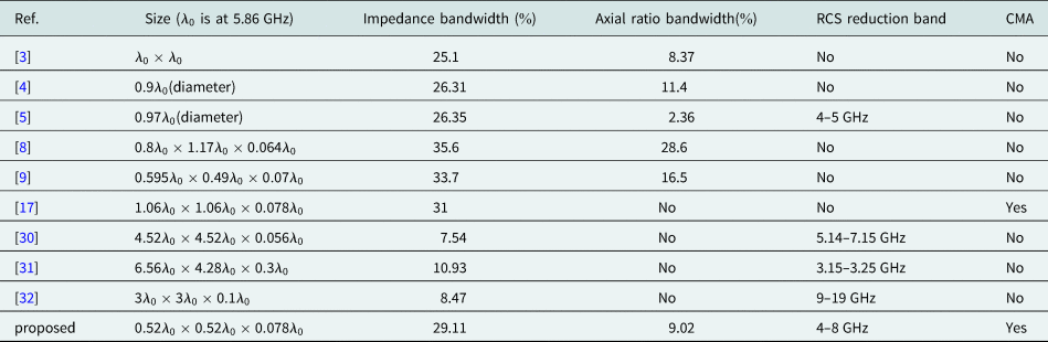
  $-15$ dB is obtained in both principle planes.The performance comparison of the proposed design is shown in Table 1.

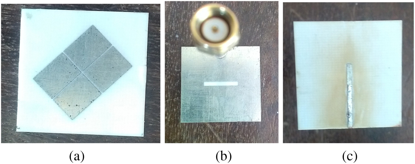
Fig. 13. Prototype of the fabricated antenna: (a) front view(MTS), (b) back view(slot), (c) micro-strip line feed.
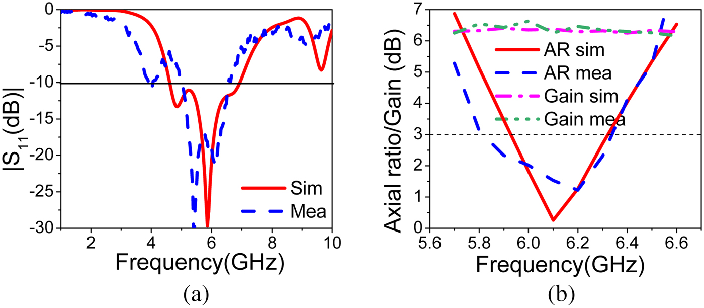
Fig. 14. Simulated and measured  $S_{11}$, axial ratio, and gain: (a)
  $S_{11}$, (b) axial ratio and gain.
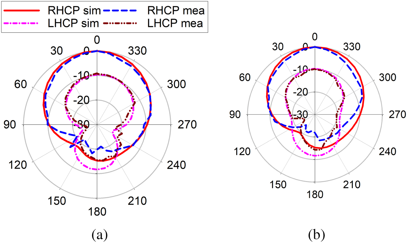
Fig. 15. Simulated and measured RHCP and LHCP. Radiation pattern at 5.86 GHz: (a) xz plane, (b) yz plane.

Fig. 16. Simulated and measured RHCP and LHCP. Radiation pattern at 6.3 GHz: (a) xz plane, (b) yz plane.
Table 1. The performance comparison of the proposed antenna.

Conclusion
A CP antenna based on PDMTS with in-band RCS reduction capability is proposed. The PDMTS is analyzed using CMA to find two orthogonal degenerate modes to achieve CP. The polarization conversion capability of PDMTS from LP wave to CP wave is successfully validated. The antenna hasa low profile with good in-band RCS reduction capability. The proposed PDMTS CP antenna achieves impedance bandwidth of 1.57 GHz and 3 dB axial ratio bandwidth of 0.49 GHz. CMA is the powerful method in analyzing the modal behavior, excitation of modes, and feed optimization.
 Puneeth Kumar Tharehalli Rajanna received his B.E. degree in telecommunication engineering and M.Tech. degree in digital communication engineering from Visveswaraya Technological University, Belgaum, Karnataka, India, in 2009 and 2013, respectively. He is currently working toward his Ph.D. in electronics and communication at the National Institute of Technology Karnataka, Mangalore, India. His field of research includes metamaterial-based antennas, microwave antennas, and microstrip antennas.
 Karthik Rudramuni received his B.E. degree in electronics and communication engineering and M.Tech. degree in radio frequency and microwave engineering from Visveswaraya Technological University, Belgaum, Karnataka, India, in 2009 and 2013, respectively. He is currently working toward his Ph.D. in electronics and communication at the National Institute of Technology Karnataka, Mangalore, India. His field of research includes metamaterial-based antennas, Goubau line-based leaky wave antennas, and microstrip antennas.
 Krishnamoorthy Kandasamy received his B.E. degree in electronics and communication engineering from Bharathiar University, Coimbatore, India, in 2003, his M.E. degree in communication systems from the College of Engineering, Guindy, Anna University, Chennai, India, in 2007, and his Ph.D. in electrical engineering from IIT Bombay, Mumbai, India, in 2016. He is currently an assistant professor at the Department of Electronics and Communication Engineering, National Institute of Technology Karnataka, Surathkal, India. His current research interests include metamaterials, antenna engineering, microwave integrated circuits (MICs), and monolithic MICs.