I. INTRODUCTION
In contemporary microwave electronics, a broad operational bandwidth of the utilized components such as directional couplers is often a primary objective. The bandwidth offered by single-section coupled-line directional couplers, reaching one frequency octave, is in many applications insufficient. Multi-octave bandwidth can be achieved either by means of cascading several quarter-wave-long sections of uniformly coupled lines [Reference Levy1] or by means of non-uniform coupled lines [Reference Tresselt2, Reference Gruszczyński and Wincza3]. Such solutions require, however, that the coupling level of the coupled lines has to be locally much higher than the nominal coupling of the resulting coupler. In many practical realizations, very tight coupling is difficult to achieve, hence several alternative methods have been proposed. In [Reference Lange4], Lange type couplers have been shown in which several parallel coupled lines appropriately connected are used. Another solution involves re-entrant type structures [Reference Cohn5], where floating strip is placed on additional dielectric layer allowing for increasing mutual coupling between coupled lines. In contrary, a tightly coupled directional coupler can be designed as a tandem connection of two loosely coupled directional couplers [Reference Shelton6]. A similar approach has been shown in [Reference Wincza and Gruszczynski7], where a tightly coupled section of a broadband three-section symmetric directional coupler has been realized as a tandem connection of two loosely coupled sections. A different approach for realization of three-section symmetric coupled-line couplers has been proposed in [Reference Staszek, Wincza and Gruszczynski8], where the coupler with rotated middle section has been presented allowing for reduction of the required coupling coefficient.
Recent development of left-handed (LH) metamaterials [Reference Caloz and Itoh9–Reference Staszek, Gruszczynski and Wincza11] has opened a new field of applications, including the realization of coupled-line directional couplers. A composite LH/right-handed (RH) directional coupler has been presented in [Reference Caloz, Sanada and Itoh12] allowing for realization of almost any arbitrary chosen coupling level. However, the operational band of the proposed coupler is comparable with the bandwidth of a classic single-section coupler. In [Reference Chun, Hong, Moon and Yun13], the authors have proposed the utilization of LH and RH transmission line sections inserted in-between coupled-line section in order to improve the directivity of the coupler, following the idea presented previously in [Reference Chun, Moon, Yun and Rhee14]. In both papers, the theory of small reflections has been utilized to provide the design equations, which restrict the presented solutions only to weak couplings. Even though, more than one coupled-line section has been used, the resulting coupler exhibits the properties of a single-section coupled-line directional coupler. The same structure has been investigated in [Reference Tayel and Alhakami15], where the tight-coupling directional couplers having still the properties of single-section directional couplers have been shown.
In this paper, we propose a novel two-section asymmetric coupled-line directional coupler structure, where loosely and tightly nearly quarter-wave-long coupled-line sections are connected by LH and RH transmission line sections. In contrary to the solutions presented in [Reference Chun, Hong, Moon and Yun13–Reference Tayel and Alhakami15], the proposed circuit features the properties of two-section asymmetric coupled-line couplers. Moreover, it has been shown that such couplers do not require as strong coupling of a tightly coupled section as classic directional couplers presented, e.g. in [Reference Levy16]. The theoretical analysis revealed that the proposed structure allows for very flexible parameter selection to ensure equal-ripple frequency response for a fixed bandwidth or for a maximum available coupling coefficient. Either way, the proper selection of parameters allows for the design of couplers with equal-ripple coupling characteristics. The numerical analysis of 3 dB couplers for various different coupling ripples has been performed and the values of optimum coupling coefficients and electrical lengths for such couplers are given in a tabular form. The proposed method has been experimentally verified by the design of a 3 dB coupled-line directional coupler where the coupling coefficient of a tightly coupled section has been reduced by the factor of k 1/k 1classic = 0.91.
II. THEORETICAL ANALYSIS
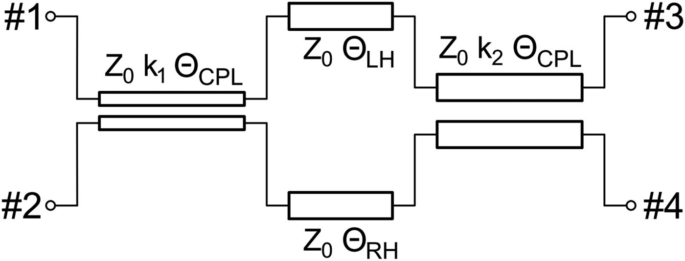
A generic schematic of the proposed directional coupler consisting of two coupled-line sections having equal electrical length connected with the use of LH and RH uncoupled transmission lines is presented in Fig. 1. Such a coupler's structure can provide broadband equal-ripple frequency characteristics being similar to the frequency characteristics of the classic two-section coupled-line directional couplers. Simultaneously, the presented network allows for significant reduction of the required coupling coefficients. The proposed structure is described by: Z 0 – characteristic impedance, k 1, k 2 – the coupling coefficients of the coupled-line sections and ΘLH, ΘRH, ΘCPL – the electrical lengths of LH, RH uncoupled transmission lines and coupled-line sections, respectively. The coupling characteristic of the presented directional coupler can be expressed as follows [Reference Park and Lee17]:

Fig. 1. A generic schematic of the proposed directional coupler consisting of tightly and loosely coupled-line sections connected by LH and RH uncoupled transmission lines.
The coefficients C i, T i (i = 1, 2) are the coupling and transmission coefficients, respectively, of particular coupled-line sections, given by the well-known formulas [Reference Mongia, Bahl and Bhartia18]:
 $$C_i=\displaystyle{{jk_i \sin \lpar {\Theta_{CPL} f} \rpar } \over {\sqrt {1 - k_i ^2 } \cos \lpar {\Theta_{CPL} f} \rpar +j\sin \lpar {\Theta_{CPL} f} \rpar }}\comma \; $$
 $$T_i=\displaystyle{{\sqrt {1 - k_i ^2 } } \over {\sqrt {1 - k_i ^2 } \cos \lpar {\Theta_{CPL} f} \rpar +j\sin \lpar {\Theta_{CPL} f} \rpar }}\comma \; $$
where ΘCPL is the electrical length of the coupled-line sections and f is the normalized frequency. The remaining factors E LH and E RH are the transmission coefficients of the ideal LH and RH uncoupled transmission lines, respectively:
The derivation of the 3 dB coupler's parameters ensuring an equal-ripple frequency response leads to the equations that cannot be solved analytically; therefore, a numerical procedure has been utilized. It is based on the minimization of the following expression:
where X indicate a three-element vector having the form:
in which f 1 and f 3 are the frequencies, at which the coupling characteristic S 21 has its local maxima and f 2 is the frequency, at which the coupling characteristic has its local minimum. The exemplary frequency response obtained for initial values of coupler's parameters is illustrated in Fig. 2. It can be observed that D = 0 can be obtained only for equal-ripple frequency characteristics. Assuming that the investigated coupler is lossless, i.e.:

Fig. 2. Graphical explanation of the factor D utilized in the numerical procedure for calculating the coupler's parameters. The minimized value of D corresponds to an equal-ripple frequency response.
Equation (7) can be expressed using only coupling characteristic S 21:
which constitutes the final form utilized in the numerical procedure.
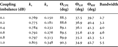
The obtained results are presented in Fig. 3, where the values of bandwidth BW (defined as a ratio of maximum and minimum frequencies, at which coupling characteristic satisfies the assumed coupling imbalance), coupling imbalance δ C and electrical lengths ΘLH, ΘRH, and ΘCPL have been plotted versus the coupling coefficients k 1 and k 2. The plotted shapes include all possible solutions for which an equal-ripple response is obtained. As it is seen, the proposed network features high flexibility in a choice of the coupler's parameters. It can be observed, that the proposed approach allows for the design of a 3 dB coupler with the assumed bandwidth with the use of different coupling coefficients k 1 and k 2. On the other hand, having fixed the maximum available coupling coefficient k 1 = k max, one can realize 3 dB couplers with different bandwidths. Such a feature, not obtainable in case of the classic coupled-line directional couplers, significantly increases the flexibility of couplers' practical realization. By analyzing Figs 3(d) and 3(e), one can see that in general the reduction of tight coupling coefficient k 1 requires the extension of the LH and RH uncoupled transmission-line sections. Simultaneously, by the slight increase of the weaker coupling coefficient k 2, the initially assumed bandwidth can be preserved in contrary to the classic coupled-line couplers, in which the reduction of tight coupling coefficient results implicitly in the bandwidth reduction (Table 1).

Fig. 3. Parameters of the proposed 3 dB coupler ensuring equal-ripple frequency characteristics vs. coupling coefficients k 1 and k 2: bandwidth (a), coupling imbalance (b) the electrical length of the coupled-line sections (c), the electrical lengths of RH and LH uncoupled transmission lines (d) and (e), respectively. The white area represents the set of coupling coefficients, using which the equal-ripple frequency response with the coupling imbalance δ C≤1 dB cannot be obtained. Assumed resolution of coupling coefficients Δk = 0.001.
Table 1. Parameters of the proposed 3 dB directional coupler ensuring equal-ripple frequency characteristics for different coupling imbalance

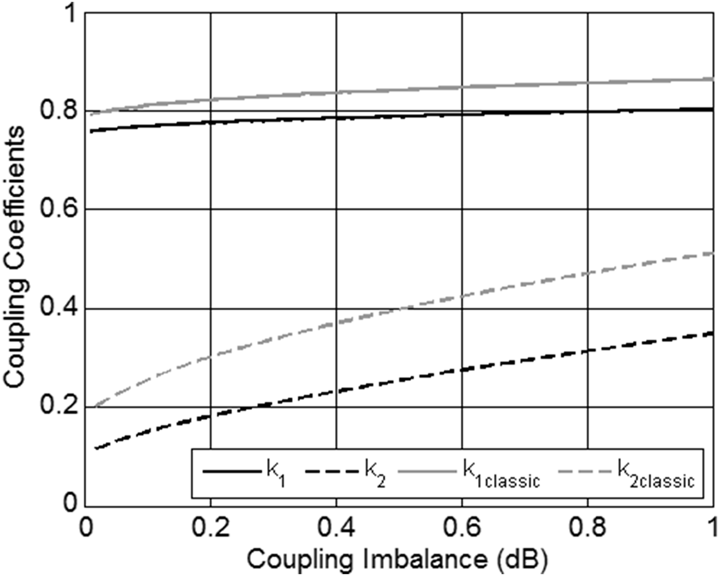
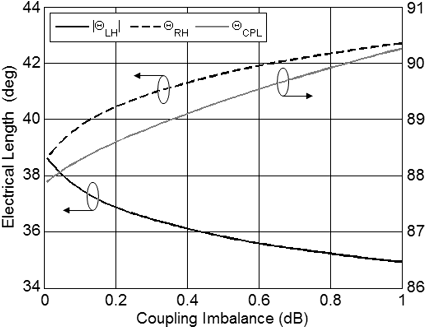
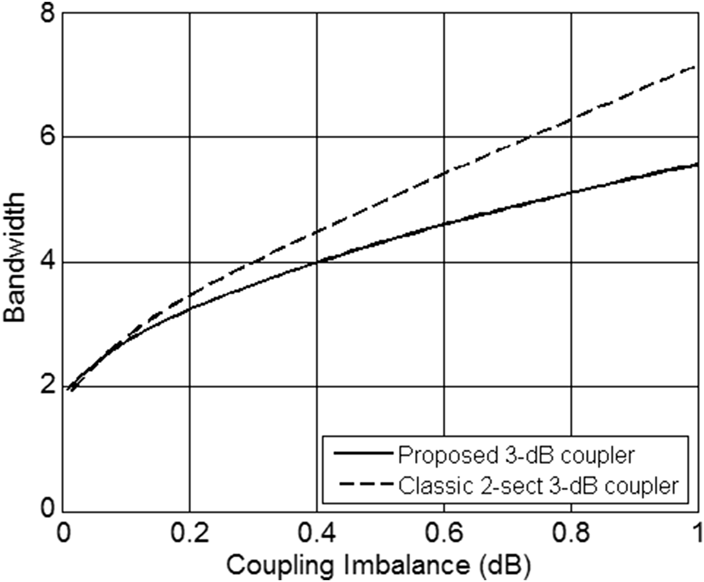
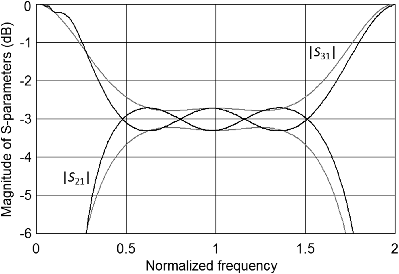
To compare the presented approach to the classic two-section coupled-line directional coupler, for each value of the coupling imbalance δ C ≤ ±1.0 dB the set of coupler's parameters, ensuring the widest obtainable bandwidth has been chosen. Such a condition results in the choice of the maximum coupling coefficient k 1 and the minimum electrical lengths of the LH and RH transmission lines, which corresponds to the upper edge of the shapes presented in Fig. 3 (the corresponding data is listed in Table 1). The comparison is shown in Figs. 4–6. As seen, despite of the chosen maximum coupling coefficient, it is still significantly lower than the one related to the classic two-section coupled-line coupler. The difference k classic – k 1max varies from 0.035 (0.38 dB) to 0.061 (0.63 dB) depending on the coupling imbalance. Figure 7 presents the exemplary ideal frequency response with the coupling imbalance δ C = ±0.3 dB compared to the classic directional coupler consisting of two quarter-wave-long coupled-line sections having the same coupling coefficients as in case of the proposed 3 dB directional coupler. As seen, the proposed approach allows for the design of a 3 dB coupler featuring equal-ripple frequency characteristics utilizing significantly reduced coupling coefficient, what cannot be achieved with the use of the classic two-section coupled-line directional coupler. Nevertheless, as a trade-off, the proposed structure results in slight decrease of the operational bandwidth in comparison with the classic solution.

Fig. 4. The coupling coefficients ensuring equal-ripple frequency characteristics and the maximum bandwidth of the proposed 3 dB directional coupler versus its coupling imbalance compared to the coupling coefficients of the classic two-section directional coupler.

Fig. 5. Electrical lengths of particular components ensuring equal-ripple frequency characteristics and the maximum bandwidth of the proposed 3 dB directional coupler versus its coupling imbalance.

Fig. 6. The maximum bandwidth of the proposed 3 dB directional coupler versus its coupling imbalance compared with the bandwidth of the classic two-section directional coupler having the corresponding coupling imbalance.

Fig. 7. The exemplary ideal frequency response of the proposed 3 dB directional coupler with the coupling imbalance δ C = ±0.3 dB (black lines) compared with the classic directional coupler consisting of two coupled-line sections having the electrical length equal to 90° and the same coupling coefficients (gray lines).
III. EXPERIMENTAL RESULTS
The proposed method has been experimentally verified by the design and measurements of an exemplary two-section 3 dB asymmetric directional coupler operating at the center frequency of 1.5 GHz. The chosen dielectric structure is presented in Fig. 8(a), in which the conditions for ideal coupled-line section realization are not met, i.e. the capacitive and inductive coupling coefficients are not equal. To equalize the coupling coefficients, and therefore, to improve directivity and impedance match of the resulting coupled-line sections, a method proposed in [Reference Gruszczynski and Wincza19] has been used. In the chosen dielectric structure the maximum coupling level equals k max = 0.75 (C = 2.5 dB). In order to realize a two-section asymmetric coupler having the nominal coupling C = 3 dB with coupling imbalance δ C = ±0.25 dB, based on the analysis presented in Section II, coupled-line sections having electrical lengths ΘCPL = 89.6° and coupling coefficients k 1 = k max = 0.75 and k 2 = 0.129 need to be connected using LH and RH transmission lines having electrical lengths ΘLH = 80.8° and ΘRH = 88.8°, respectively. The resulting bandwidth equals BW = 2.9. On the other hand, to obtain the same nominal coupling and imbalance in a classic configuration [Reference Levy16], the following coupling coefficients are required k 1classic = 0.824 and k 2classic = 0.315, whereas the resulting bandwidth equals BW classic = 3.7. By comparing coupling coefficients of tightly coupled sections of both couplers, it is seen that the required coupling coefficient is reduced in the proposed solution by the factor of k 1/k 1classic = 0.91 at the expense of bandwidth reduction of BW/BW classic = 0.78.

Fig. 8. Cross-sectional view of dielectric structure (a) and pictures of the manufactured 3 dB two-section asymmetric directional coupler where tightly and loosely coupled sections are connected using RH and LH transmission line sections: top side view of assembled coupler (b), view of the top metallization layer (c) and view of the bottom metallization layer (d).
The LH section has been physically realized with the use of a two-section T-type LC equivalent circuit. The elements' values have been calculated according to [Reference Sorocki, Piekarz, Wincza and Gruszczynski20] and are equal L LH = 7.52 nH and C LH = 3.01 pF. The required inductors have been realized using high-impedance transmission-line sections, whereas capacitors have been realized using 2.7 pF SMD 0402 chip capacitors, what enforced a slight circuit tuning. Parasitic reactances introduced by the transition regions between physically realized coupled and uncoupled lines, have been compensated using lumped capacitances [Reference Gruszczynski, Wincza and Sachse21].
The designed circuit has been electromagnetically calculated using AWR Microwave Office software, manufactured and measured. Photographs of the circuit are presented in Figs 8(b)–8(d), whereas the simulation and measurement results are shown in Fig. 9. As it is seen, the developed coupler features equal power split with imbalance δ C = ±0.4 dB. The isolation is better than 18 dB and return losses are better than 15 dB over the entire operational bandwidth being equal to BW = 3.

Fig. 9. Calculated (dotted lines) and measured (solid lines) amplitude characteristics of the designed 3 dB two-section asymmetric directional coupler.
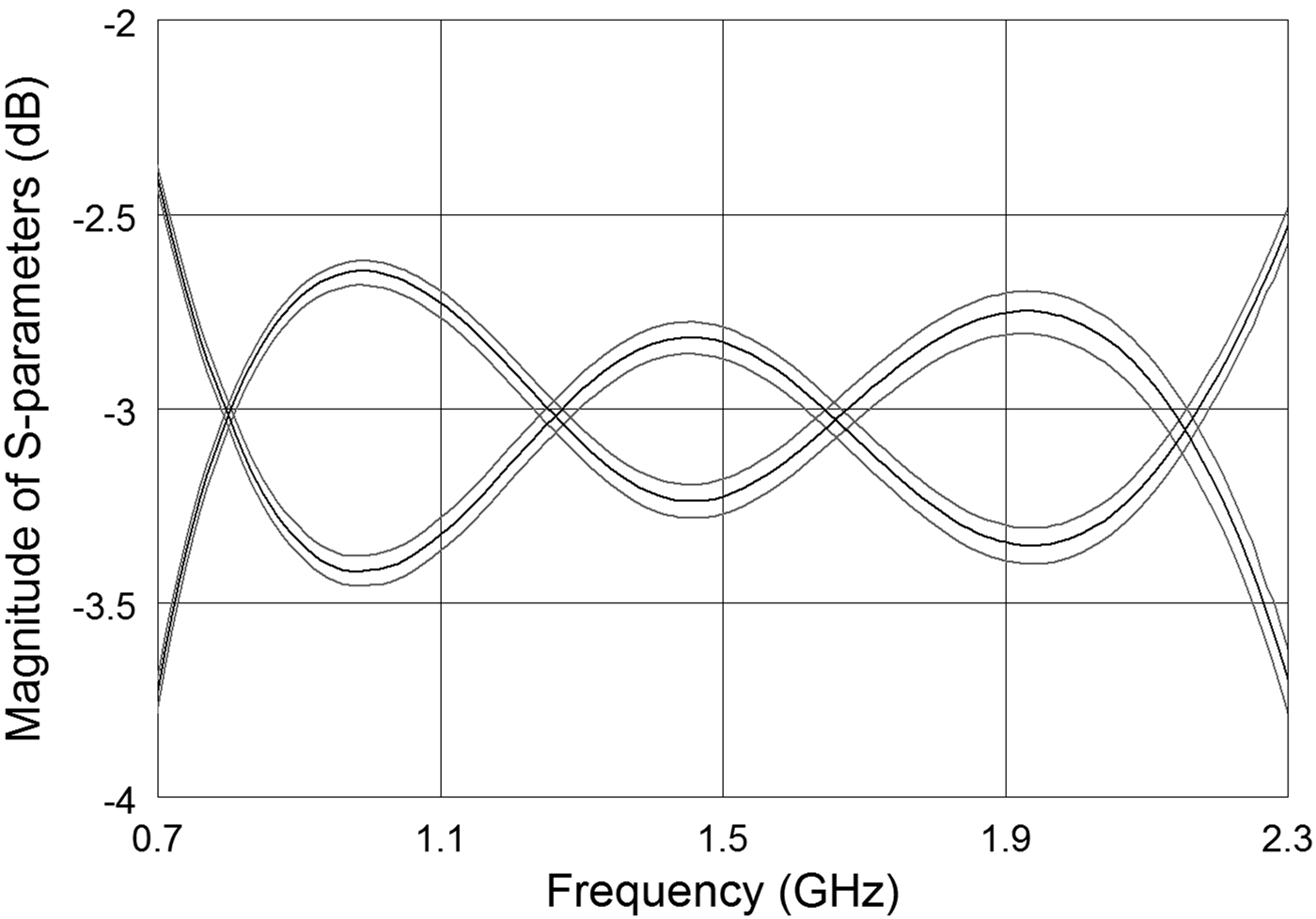
Furthermore, the tolerance of physical dimensions on the frequency response has been verified. The entire coupler's structure has been electromagnetically analyzed for the widths of coupled lines being deteriorated by ±20 µm (typical tolerance values for PCB manufacturing processes). The calculated coupling and transmission coefficients are given in Fig. 10. As it is seen the deterioration of frequency response resulting from the manufacturing tolerance is insignificant.

Fig. 10. Deterioration of the frequency response for the designed 3 dB directional coupler resulting from ±20 µm tolerance of the coupled line width. Results of electromagnetic calculations.
IV. CONCLUSIONS
A design technique of two-section asymmetric coupled-line directional couplers with the reduced coupling coefficient requirements has been presented together with the theoretical analysis, design methodology, and experimental verification. Measurement results are in good agreement with the theoretical ones confirming the correctness and usability of the proposed method. The major advantage of the presented solution is the possibility of realization of directional couplers having broadband amplitude characteristics in dielectric structures, where tight coupling that is required in a classic approach is not achievable. Another advantage of the presented approach is that it allows for very flexible parameters' selection ensuring an equal-ripple coupling characteristic for the assumed bandwidth or maximum available coupling coefficient.
ACKNOWLEDGEMENTS
This work was partially supported by the National Research Centre under contract no. UMO-2011/01/D/ST7/00789 and in part by the Polish Ministry of Science and Higher Education under grant no. 0604/IP2/2011/71.


