


Introduction
As the development of the long-distance wireless communication systems (such as long-street, long bridges, tunnels, highways, and railways), bidirectional antenna array has received ever-increasing attention due to its special opposite converge radiation pattern and high gain characteristics. In the past decades, a lot of researches have been done to design the bidirectional antennas [Reference Liu, Zhang, Tian and Feng1–Reference Guo and Geyi6]. In [Reference Liu, Zhang, Tian and Feng1], a bidirectional end-fire antenna array with six parasitic elements is developed for coal mine or tunnel communication. A novel design of the bidirectional antenna based on spoof surface plasmon has been successfully implemented with good performance in [Reference Tian, Xu, Peng, Li, Xu, Zhang and Ren2]. Meanwhile, a number of the circularly polarized (CP) or the polarization reconfigurability bidirectional antenna array has been designed [Reference Shen, Lu, Cao, Yang and Li7–Reference Wang, Wang, Gao, Ding and Wang10]. In [Reference Shen, Lu, Cao, Yang and Li7], a slot antenna with a broadband CP bidirectional radiation pattern is proposed for the X-band applications. However, the aforementioned designs, which are all based on the metal, usually suffer from the conductor loss of the metal as the operation frequency arises.
Dielectric resonator (DR) antenna, for its near-zero conductor loss, more degrees of design freedom, small size, light weight, and ease of excitation, becomes more attractive [Reference Lai, Almpanis, Fumeaux, Benedickter and Vahldieck11–Reference Gaurav, Pandey and Yaduvanshi15]. In [Reference Das, Sharma, Gangwar and Sharawi13], a bidirectional diversity antenna using stacked DRs is designed. However, its high profile would become an obstacle in some applications that have limited space.
In this paper, the DR antenna array with bidirectional radiation is proposed for the first time. The strip-loaded DR operating at the higher-order TE3δ1 mode is used as a magnetic dipole to design a high-gain quasi-Yagi antenna without extra directors. By placing the two quasi-Yagi antennas back-to-back, which are fed by a new dual Marchand balun, an antenna array comes into being, achieving a bidirectional radiation pattern. The simulated and measured results with good consistency are presented, which effectively verifies the proposed idea.
Antenna design
The geometry of the proposed bidirectional DR antenna array is shown in Fig. 1, which is integrated on a RO4003C substrate (εr 1 = 3.55 and tanδ 1 = 0.0027). The ground plane is on the bottom of the substrate. As depicted in Fig. 1, the antenna array is composed of two quasi-Yagi antenna elements. A dual Marchand balun, which can be seen as two traditional Marchand baluns placed back-to-back [Reference Tseng and Hsiao16, Reference Lee and Tsai17], is employed to excite the antenna array.
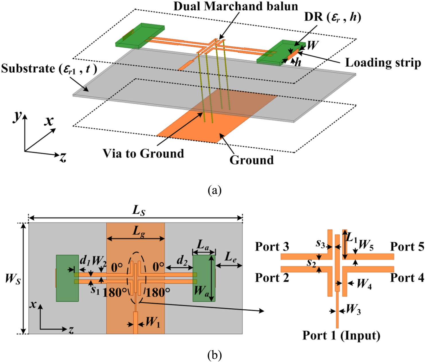
Fig. 1. Geometry of the bidirectional DR antenna array. (a) 3D view. (b) Top view. (Design parameters: LS = 69.8, WS = 32.5, La = 6.5, Wa = 13.6, Lg = 16.9, Le = 8, W = 5.6, W 1 = 1.2, W 2 = 1.2, W 3 = 0.35, W 4 = 0.7, W 5 = 0.9, L 1 = 4.5, d1 = 1.2, d2 = 8.2, s 1 = 0.8, s 2 = 0.8, s3 = 0.15, h = 1, and t = 0.508. Units: mm.)
Quasi-Yagi antenna element
Figure 2 illustrates the configuration of the proposed quasi-Yagi antenna element, which is composed of a rectangular DR partially printed with a metal strip, one layer of the substrate, a transition of differential microstrip line pair to groundless balanced coplanar strip line (CPS) for differential excitation of the DR, and ground plane (used as a reflector) on the bottom of the substrate. The quasi-Yagi antenna element based on the dominate TE1δ1 mode DR is proposed in [Reference Qian, Sun, Zhang and Chen18] and the antenna gain can be improved as compared with the traditional quasi-Yagi antenna using metal strips. However, the gain improvement is still limited and can be further enhanced. Since the DR owns multiple higher-order mode characteristic, they can be excited to achieve gain enhancement [Reference Petosa and Thirakoune19–Reference Shahadan, Jamaluddin and Kamarudin22]. In this design, the rectangular DR operating at higher-order TE3δ1 mode is used as a magnetic-dipole driver, which implies higher gain can be achieved. Table 1 gives the performance comparison of the proposed antenna using the higher-order TE3δ1 mode (without loading strip here) with the previous quasi-Yagi antenna element in [Reference Qian, Sun, Zhang and Chen18]. The antenna gain is about 2.46 dBi higher than that of the design in [Reference Qian, Sun, Zhang and Chen18]. According to the TE3δ1 mode E-field distribution in Fig. 3(a), the CPS feeding line should be symmetric with respect to the central line of the DR so that the E-field directions of the CPS and TE3δ1 mode of the DR are consistent. Meanwhile, the strip width W 2, the spacing s 1 between the two strips, and the inset length d 1 of the CPS can be optimized to obtain good impedance matching for the quasi-Yagi antenna element. As can be seen from Fig. 3(a), the TE3δ1 mode has three E-field circles tangential to the x–z plane, and it is undesirable that the E-field direction along the right-side wall (x-axis direction) of the middle circle is opposite to those of its both sides. To overcome this, a metal strip with a length of about 1/3Wa is printed on the side wall of the DR for compressing the middle E-field, as shown in Fig. 3(b), so that the antenna gain can be enhanced. Figure 4 shows the simulated radiation pattern for the quasi-Yagi antenna element with/without loading strip. It can be found that the back lobe of the radiation pattern of the antenna with a loading strip is compressed and therefore both end-fire gain and front-to-back ratio are improved. Figure 5 shows the simulated peak gain of the antenna element with/without strip under different extension length Le of the substrate. It can be found that the gain of the antenna can also be enhanced by increasing Le. Thanks to the employment of high-order TE3δ1 mode and loading strip, the antenna gain can reach up to 9.4 dBi without director when Le = 20 mm. Accordingly, the optimization for the directors in the traditional Yagi antenna can be avoided.

Fig. 2. Geometry of the proposed quasi-Yagi DR antenna element. (a) 3D view. (b) Top view. (Design parameters: W 2 = 1.1, W 5 = 1.2, d 2 = 8, Le = 20, and s 1 = 1.5. Units: mm.)

Fig. 3. The TE3δ1 mode E-field distributions of the DR. (a) Without loading strip. (b) With loading strip.

Fig. 4. The simulated radiation patterns for the quasi-Yagi antenna element with/without loading strip. (a) E-plane. (b) H-plane.

Fig. 5. Effects of the substrate loading on the quasi-Yagi DR antenna element with/without loading strip.
Table 1. Performance comparison with the previous antenna element in [Reference Qian, Sun, Zhang and Chen18].

Figure 6(a) shows the simulated reflection coefficient (|S 11|) of the proposed antenna element. The simulated impedance bandwidths for |S 11|<−10 dB are 100 MHz (10.45–10.55 GHz). Figure 6(b) depicts the simulated radiation patterns in both E- and H-planes at about 10.5 GHz, respectively. As can be seen, the front to back ratio is about 18 dB, which indicates that the antenna element owns good end-fire radiation patterns. Due to the adoption of the differential-fed scheme in this design, the proposed antenna has lower cross-polarization.

Fig. 6. Simulated results of the quasi-Yagi antenna element with loading strip. (a) Reflection coefficient. (b) Radiation pattern at 10.5 GHz.
Design of bidirectional antenna array
According to the above discussion, the DR quasi-Yagi antenna with end-fire radiation is employed as an element for constructing the bidirectional antenna array, which is fed by a dual Marchand balun, as shown in Fig. 1. In this balun, a half-guided wavelength (λg/2) microstrip line in the middle is fed by port 1, which is used as the input port of the array. Each side involves two λg/4 microstrip lines with one short-circuited end while two pairs of output ports (i.e. ports 2 and 3, and ports 4 and 5) are used as balanced outputs. Meanwhile, port 2 (3) and port 4 (5) are in-phase. By optimizing the key parameters (W 4, W 5, d 1 and d 2), good performance can be obtained, as shown in Fig. 7. The phase difference between ports 2 (4) and 3(5) is within 180 ± 3° in the frequency range of 10.2–10.5 GHz, meanwhile the in-phase characteristics between ports 2 (3) and 4 (5) are also good. With two pairs of differential signals, the antenna array can be well excited. In the proposed bidirectional design, the back radiation of one antenna element is the front main radiation of another. Therefore, to obtain good bidirectional radiation performance, the distance between the two DR drivers should be optimized and the optimum length Lg of the ground is determined as 16.9 mm.

Fig. 7. The simulated results of the proposed dual Marchand balun. (a) S-parameters. (b) Phase differences.
Results and discussion
For verification, a bidirectional DR antenna array, which has a volume of 2.4 λ 0 × 1.12 λ 0 × 0.05 λ 0 (λ 0 represents the free-space wavelength at the center frequency), is fabricated as shown in Fig. 8. Figure 9(a) shows the simulated and measured reflection coefficients (|S 11|) and realized gains of the proposed antenna array. The simulated and measured impedance bandwidths for |S 11|<−10 dB are 70 MHz (10.3–10.37 GHz) and 80 MHz (10.3–10.38 GHz), respectively. The measured maximum gain reaches up to 7.58 dBi, which is slightly lower than the simulated value 7.78 dBi. It can be concluded that the gain of the bidirectional array is improved by tuning Lg as compared with the quasi-Yagi antenna element mentioned above, and the improvement is [(7.58 + 3)–9.4] = 1.18 dB. The measured and simulated results of radiation patterns on E- and H-plane at 10.34 GHz are illustrated in Fig. 9(b). A slight discrepancy between the simulated and measured results can be observed, which mainly comes from fabrication tolerance and measurement imperfection. Figure 9(c) gives the simulated and measured efficiencies of the proposed bidirectional antenna array. It can be seen that the simulated and measured radiation efficiencies are more than 88 and 81% in the operating band, respectively.
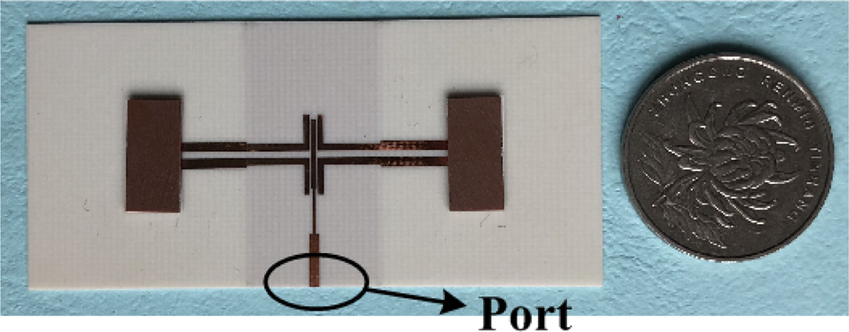
Fig. 8. Photograph of the fabricated bidirectional antenna array prototype.
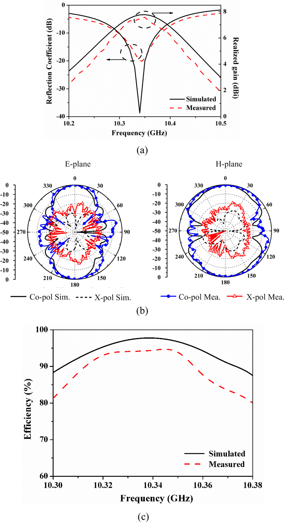
Fig. 9. Measured and simulated results of the proposed bidirectional antenna array. (a) Reflection coefficients and realized gains. (b) Radiation pattern at 10.34 GHz. (c) Radiation efficiency.
The performance comparison of the proposed bidirectional antenna array is summarized in Table 2. It can be found that the proposed antenna without director has comparable radiation gain to that of the design based on the SPP with four directors in [Reference Tian, Xu, Peng, Li, Xu, Zhang and Ren2]. As a result, the overall electrical length of the proposed design is shortened by about one λ 0. Benefitting from the gain enhancement techniques using the high-order mode and loading strip, the antenna gain is about 1.8 dB higher than that of the design with two directors in [Reference Wang, Wang, Gao, Ding and Wang10]. Remarkably, it is much higher than that of the design based on the stacked DRs without director [Reference Das, Sharma, Gangwar and Sharawi13]. In addition, the proposed bidirectional antenna array using the dual Marchand balun differential feeding structure has relatively lower cross-polarization over the previous antenna in [Reference Tian, Xu, Peng, Li, Xu, Zhang and Ren2] and [Reference Das, Sharma, Gangwar and Sharawi13]. Remarkably, the measured maximum radiation efficiency is up to 95%, even comparable to that of the design operating at 5.5 GHz in [Reference Tian, Xu, Peng, Li, Xu, Zhang and Ren2].
Table 2. Performance comparison with the previous bidirectional antenna arrays.

Conclusion
A bidirectional antenna array based on the DR has been presented in this letter. The strip-loaded DR operating at the higher-order TE3δ1 mode is employed to design a gain-enhanced quasi-Yagi antenna element without extra directors. By using the dual Marchand balun as a feeding network, the antenna array achieves a bidirectional radiation pattern. To verify the design, a prototype has been fabricated and measured. Good agreement between the simulated and measured results can be observed. The high performance of the proposed antenna array would make it attractive in future communications.
 Ling-Ling Yang was born in Nantong, Jiangsu Province, China, in 1987. She received the B.Sc. degree in electronic science and technology from Nantong University Xinglin College, Nantong, China, in 2009, and the M.Sc. degree in information and communication engineering from Nantong University, Nantong, China, in 2012. Since 2012, she has been with Xinglin College, Nantong University, where she is currently a Lecturer. Her current research interest is microwave antenna.
 Yan-Hui Ke was born in Wuxi, Jiangsu Province, China, in 1998. He is currently pursuing the B.Sc. degree in information and communication engineering from Nantong University, Nantong, China. His current research interests include filter and antenna.
 Jian-Xin Chen received the B.S. degree from Huai Yin Teachers College, Huai'an, China, in 2001, the M.S. degree from the University of Electronic Science and Technology of China (UESTC), Chengdu, China, in 2004, and the Ph.D. degree from the City University of Hong Kong, Hong Kong, in 2008. Since 2009, he has been with Nantong University, Nantong, China, where he is currently a Professor. He has authored or co-authored more than 100 academic papers. He holds 15 Chinese patents and three US patents. His research interests include RF/microwave differential circuits and antennas, dielectric resonator (DR) filters, and low-temperature co-fired ceramic circuits and antennas. Dr. Chen received the Best Paper Award presented at the Chinese National Microwave and Millimeter-Wave Symposium, Ningbo, China, in 2007. He was the Supervisor of 2014 iWEM student innovation competition winner in Sapporo, Japan.


