


I. INTRODUCTION
One of the visions pursued by Continental is to make individual mobility safer, more sustainable, more comfortable, and affordable, and to help avoid accidents (Vision Zero) and injuries as far as possible. Modern forward-looking driver assistance systems can support the driver in assessing the situation, considerably reduce the reaction time, find the optimum reaction strategy, or operate autonomously if the driver is inattentive [Reference Bishop1]. A key element of the so-called Advanced Driver Assistance Systems (ADAS) is radar sensors for environmental observation [Reference Winner, Hakuli and Wolf2, Reference Rasshofer and Fitzek3]. The A.D.C. GmbH as a part of Continental's new business unit ADAS has been one of the leading suppliers of radar sensors for automotive comfort and safety systems since 1999. According to the state of science, a frequency bandwidth of 1–2 GHz is required for reliable measurement of the vehicle's surroundings [Reference Andres, Feil, Menzel, Bloecher and Dickmann4]. From a regulatory perspective, such sensors are classified as ultra-wideband (UWB) sensors. These sensors have been operating in a frequency range of 24 GHz so far. In the EU, it will become mandatory from 2018 [5] that new equipment for automotive applications must only use the frequency range of 76–81 GHz. The substitution of expensive GaAs components by lower-cost SiGe components has already been accomplished in the 24 GHz frequency range. To accelerate this technology change at 79 GHz and to make it economically viable was the central task of the RoCC project [6]. Five companies – Daimler AG, BMW Research and Technology GmbH, Robert Bosch GmbH, Continental AG, and Infineon Technologies AG – cooperated in the joint RoCC project that was funded by the BMBF with a budget of 8.3 million euros, in order to enhance safety on the roads and make future sensors affordable for all car segments. The joint RoCC project, which is the continuation of the “KOKON” project, was launched in September 2008 and ended for Continental in February 2012.
II. PROJECT WORK
A) Area of operation
The first ADAS introduced in the market were comfort systems, i.e. the adaptive cruise control (ACC) function. During the past few years, safety functions gained more and more importance and market share. Most safety functions are located in the near and mid-range around the car. Examples are blind spot detection, emergency brake assistance, precrash detection, crash mitigation, pedestrian protection, parking and reversing aid, assistants for turning, crossings, and construction areas [Reference Bishop1].
Regarding the megatrend of progressive urbanization, the urban environment will be of special importance for future system and sensor design, i.e. for application in future “city assistants”. For this, short- and mid-range radar (SRR and MRR) sensors are predestined. The market research company Strategy Analytics predicts a market for about 10 million SRR and MRR sensors in 2014 with a strong growth during the next year [Reference Mak7].
B) Radar principle
The radar method selected for our sensors is the pulse compression technique. The method, which is also called chirp-sequence-modulation [Reference Winner, Hakuli and Wolf2], allows for optimal use of signal power, bandwidth, and measuring time. It is a combination of a pulsed and an Frequency Modulated Continuous Wave (FMCW) radar. Very fast frequency ramps lead to a frequency shift of every received signal due to the delay caused by the time-of-flight (Fig. 1). The received signal is downconverted with the transmit signal as LO. Sampling and Fourier transform of this IF signal results in a discrete set of data corresponding to the range gates, as the frequency shift caused by the Doppler effect is so small that it can be neglected completely in this first Fourier transform. Subsequently, by processing and evaluating the complex distance values from the successive ramps by a second Fourier transform, the phase rotation that corresponds to the Doppler frequency is determined [Reference Lüke, Wintermantel, Raste and Rieth8, Reference Wintermantel9].

Fig. 1. Emitted and received frequencies using chirp-sequence-modulation.
The advantage of this method is that the distance-related frequency shift and the Doppler shift are separated and do not lead to any ambiguity, unlike the conventional FMCW method. Hence, distance and velocity are determined independently. Another advantage of this method is a basic resistance to interferences by other RF sources. For a further improvement of protection against the radiation of similar sensors, a small statistical variation of the onset time of the frequency ramps was implemented. This leads to a strong reduction in sensitivity to non-correlated radiation patterns from other sensors since interference resistance is an essential requirement for automotive safety systems with high equipment rates.
Sampling and windowing of the Fourier transform restricts the resolution and maximum range of distance measurement. In the RoCC sensor, we calculate 112 range gates. Using a maximum detection range of 111 meters for a mid-range mode leads to a range resolution of 1 m. This resolution is crucial for the separation of different targets at different distances. The accuracy of the measurement is typically much better. A resolution of about 0.2 m for a short-range mode can be achieved by choosing a maximum range of 22 m. The respective parameters of the sensor can be switched between these operating modes. The range selection corresponds to a bandwidth of 0.2–1 GHz, respectively.
C) Sensor architecture
During the past few years, automotive radar sensors used quasi-optical beamforming [Reference Winner, Hakuli and Wolf2, Reference Menzel10, Reference Hasch, Topak, Schnabel, Zwick, Weigel and Waldschmidt11] via reflectors or lenses, or mechanically scanning concepts [Reference Wintermantel and Rasshofer12, Reference Menzel and Moebius13] for providing angular resolution and target separating capability. A simpler and more robust mechanical construction and an enhanced resolution are provided by electronically scanning concepts such as digital beamforming (DBF) [Reference Stelzer, Feger and Jahn14]. To meet the current requirements, DBF systems typically need more transmit/receive channels with separate antennas than conventional systems [Reference Winner, Hakuli and Wolf2, Reference Menzel10, Reference Hasch, Topak, Schnabel, Zwick, Weigel and Waldschmidt11]. Only the introduction of the cost-effective SiGe technology with its potential for integration [Reference Knapp, Lachner, Bredendiek and Pohl15] allows the production of competitive multi-channel sensors. For the implementation of the DBF concept, we use two transmit and four receive channels, which are provided by two integrated SiGe components, one receiver module and one transmitter module (Fig. 2). This partitioning reduces the number of 79 GHz RF-lines on the board and allows a high flexibility in the scaling of future products and their adaptation to different applications.

Fig. 2. RF system setup.
Differential mode transmission lines are used in order to achieve improved insensitivity to interference. The frequency ramps are generated by the control voltage of a voltage-controlled fundamental oscillator (VCO) inside the transmit IC. A frequency divider provides a test signal to control ramp frequency. Three coherent signals with a high output power of approximately 9 dBm are derived from the VCO via three power amplifiers. One of these output signals is delivered to the receiver IC that consists of four individual mixers which downconvert the incoming signals of the four receiving antennas in parallel. A signal processor interface is used to control the function of the SiGe components. To reduce the number of the board-to-board connection lines, the downconverted signals are multiplexed.
The power budget over the entire transmission chain starts with 7 dBm of transmit power at the antenna feed point. Taking into account an antenna gain of 18 dB, a two-way attenuation of −153 dB, and a radar cross section of 3 dBsm of an average motorbike, we estimate a receive power of −107 dBm. Based on this result, we expect the sensor to be able to detect all relevant objects in the envisaged distance of 60 m. For a passenger car, we observe typical values of the radar cross section of 10–15 dBsm and a detection range of 90 m.
D) Signal processing steps
A block diagram of the signal processing chain is given in Fig. 3. The downconverted IF-signal is multiplexed, transmitted to the electronic control unit (ECU) board, and digitized by an AD converter.

Fig. 3. Block diagram of the software modules and the sequence of operation implemented in the ECU.
The digital signal is directly fed into an Field Programmable Gate Array (FPGA). The main steps of subsequent data processing are ranging by a first fast Fourier transform (FFT), the calculation of the velocity spectrum by a second FFT, the DBF, and the detection of peaks. The resulting peak list is sent to a microcontroller (MUC). The ensuing steps in the MUC are target detection by clustering the peaks, object detection by tracking the targets, situation analysis, and finally as a result of the application function a signal is sent to the vehicle control network (CAN bus) for driver information or to initiate respective reaction of the car.
The tracker has to estimate the movement of targets, usually by applying a Kalman filter, carry out a validation of the object hypotheses, and exclude false ones or ambiguities.
The task of situation analysis is to assess the relevance of the recognized objects. It has to decide if the object is in the vehicle's lane and classify the targets. An important classification step, for example, is to distinguish between stationary or moving targets.
As a final test step we implemented the ACC function as a well-known reference to evaluate the sensor. Since, for a typical ACC function, a long-range radar (LRR) sensor is necessary, the short-range RoCC sensor was tested only in a low-speed range in the city and on main roads.
Beside this subsequent data processing chain, there are some additional modules working simultaneously in parallel. The modules for detection and suppression of interferers, for automatic angular alignment, and self-diagnosis to detect a system failure are of very special interest for all automotive safety functions. They enhance the availability and indicate to the safety system if the sensor delivers reliable data. This knowledge is the precondition for a safe operation state.
E) DBF and angular measurement
In order to equip the sensor with a cross-range resolution that meets the current requirements of the market, DBF is implemented. The sensor uses the time division multiple-in multiple-out (MIMO) principle [Reference Feger, Wagner, Schuster, Scheiblhofer, Jäger and Stelzer16] to alternately send on two separate transmit channels and successively receive on four receive channels [Reference Kees, Schmidhammer and Detlefsen17]. The total of eight downconverted and digitized received signal samples corresponds to eight virtual antenna positions. Mathematically, these positions are given by the convolution of the transmit and receive antenna positions. The resulting virtual array can show gaps between successive antenna positions or may even have overlapping positions. In the case of the presented sensor, the antenna positions are chosen in order to have eight uniform virtual antenna positions with a distance of 1.75 λ [Reference Feger, Schuster, Scheiblhofer and Stelzer18] between each other corresponding to an unambiguous range of ±17.2°. Hence, grating lobes will occur in the field of view since the first null of the farfield pattern of a single antenna element occurs at ±40°. The angular ambiguity is compensated for later in the tracking stage of radar signal processing. Beamforming is implemented calculating the zero-padded FFT of the complex samples from the eight virtual antennas of the MIMO radar and thereby transforming them into 16 angular samples [Reference Wintermantel9], with a spacing of 2.15°. Each FFT bin hereby corresponds to a different angle of arrival with an antenna lobe describing the directional-dependent sensitivity. Figure 4 shows the resulting digital center beam (centre bin) measured in an anechoic chamber using a corner reflector. The sensor was fixed on a rotating table using a gradual scanning of 1° per step. The measurement shows a 3 dB beamwidth of 4° as a result of the array factor and thus yields high-quality target separation. The measurement was carried out with a bandwidth of 800 MHz.

Fig. 4. Normalized received power over the azimuth angle measured on a corner reflector after applying DBF.
F) Antenna array
The demonstration sensor as described in this paper puts high demands on the antenna array. The specification requires high gain, broad field of view in azimuth and narrow beam in elevation for a single element. The chosen candidate for the final antenna front-end is a substrate-integrated slotted waveguide array. The theory of slotted waveguide antennas is well known and has been developed over decades, among others [Reference Elliott and Kurtz19–Reference Oliner23]. The first substrate integrated slot antennas have been presented in [Reference Hirokawa and Ando24–Reference Stephens, Young and Robertson26]. Full-wave simulation of a single slot and the extraction of its impedance properties have been addressed in [Reference Gatti, Sorrentino and Dionigi27]. Ever since, the integrated version of this type of antenna has gained more attention [Reference Shi, Yousef and Kratz28, Reference Chen and Che29].
G) Antenna design
A substrate-integrated waveguide (SIW) consists of two rows of vias forming the narrow walls of a waveguide. An array of longitudinal offset slots is etched into the upper metallization layer of the substrate which represents the broad wall of a waveguide. The slot spacing is calculated to be one-half guided wavelength at the design frequency of 79 GHz. Such an array is capable of producing a broadside beam with a nearly ±90° field of view in the E-plane (azimuth) and a highly directive beam with low side-lobes in the H-plane (elevation) depending on the slot offset configuration. The first step to design the slot array is to choose a suitable width for the SIW. The standard E-band waveguide width is scaled by the permittivity of the substrate for an initial value. On the one hand, it is important to make the SIW wider since this will increase the range of possible offset positions of the slots. Since the width also affects the dispersion curve, the widening of the SIW should not be exaggerated in order to keep the antenna pattern more stable over frequency. On the other hand, higher-order modes in the operating frequency band must be avoided. For the height of the SIW only discrete values are possible according to the available substrate thicknesses. The influence of the substrate thickness on the slot offsets is strong. For a given offset a lower substrate thickness will increase the radiation of a slot and vice versa. An antenna design with many slots will be easier to manufacture on a thicker substrate since the slots will be more strongly displaced from the centerline. Also, a thinner substrate suffers from higher-order mode coupling between the slots [Reference Elliott and O'Loughlin30]. For the presented slot antenna, the cost-efficient Rogers RO3003 substrate material was chosen.
The next step of antenna design is to determine the equivalent impedance properties of a slot in the SIW. A longitudinally offset slot in the broad wall of a waveguide only interrupts the transverse currents and thus can be represented by a shunt admittance. Using CST Microwave Studio's F-Solver [31], a commercial full-wave frequency domain solver, an elementary cell model of a slot, is simulated to precisely determine the equivalent admittance y(v,l,w) as a function of slot offset v, length l, and width w, also called active admittance. A schematic of the simulation model and the equivalent circuit of the slot are depicted in Fig. 5. The modeled waveguide is terminated with a short circuit that is transformed via a quarter-wave line into an open stub exactly in the middle of the slot. The feeding waveguide is extended by half a wavelength. The shunt admittance of the slot is thereby transformed into the port reference plane and can be derived from the reflection coefficient.
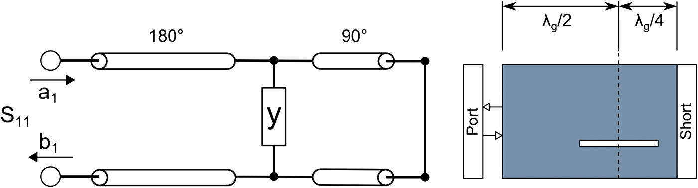
Fig. 5. Equivalent circuit (left) and corresponding simulation model (right) of a single slot.
For each possible offset, the resonant length of a slot can be found by varying its length until its admittance is purely real, i.e. the slot conductance y(v,l,w) = g(v,l,w). Now, the slot parameters can be simulated in a small range around the resonance condition, and various curves can be extracted, such as slot resonant length over offset, conductance over offset, and radiated power over offset. Then, transmission line theory is applied to model a slot antenna with arbitrary pattern in the elevation. For this procedure, two assumptions are necessary: first, only the TE 10 mode must propagate along the waveguide, and secondly, all the slots need to be in resonance. The desired antenna pattern is synthesized via array factor calculation, and the corresponding amplitude coefficients are calculated using analytical tapering functions. A set of slot offsets can be found that fulfils the pattern requirement  $a_i \mathop=\limits^! p_i=\left({{{P_i } / {P_m }}} \right)$ using the power over offset curve where the radiated power of each slot P i is normalized to the maximum radiated power P m within the set. Since the equivalent admittance of each slot is known, the input admittance of the antenna can be calculated by
  $Y_{11}=Y_0 \sum\nolimits_{i=1}^N {g_i }$ where N equals the number of slots, g i is the conductance of the ith slot, and Y 0 is the wave admittance of the SIW. Now, both the pattern requirement
  $a_i \mathop=\limits^! p_i $ and the matching condition
  $\sum\nolimits_{i=1}^N {g_i } \mathop=\limits^! 1$ need to be fulfilled simultaneously. By iteratively displacing the slots from the centerline, sets with higher input admittances can be found while maintaining the radiation pattern until
  $\sum\nolimits_{i=1}^N {g_i } \mathop=\limits^! 1$ is reached.
As a next step, a full-wave simulation of the designed antenna is carried out to verify the results. A deviation of the ideal matching condition is observed which is caused by mutual coupling between the slots. This coupling results from a higher-order mode coupling within the SIW and outer radiation coupling between the slots. Mutual coupling effects are increased both due to a reduced waveguide height of the SIW and more tightly arranged slots compared with a standard waveguide. The transmission line model, as explained above, is then violated. In principle, coupling between slots can be compensated for by using Stegen-type curves as shown in the literature [Reference Kaminow and Stegen32]. For generating these curves, the full-wave elementary cell simulation model is again used to derive the admittance properties of a slot from S 11. The real (h 1) and the imaginary (h 2) part of the admittance fully characterize the slot when it is detuned off its resonance frequency by varying its length. The common approach according to Stegen is to compensate for the mostly imaginary coupling term by changing the length of the slot. The h-curves can only be used in a small region around the resonance condition, usually a few per cent. Since the conductance of the slot is also affected by slot tuning, the matching condition cannot be fulfilled anymore. Thus, the design process needs to be started over from the beginning by calculating a new set of slot offsets making it an iterative approach.
Besides varying the length, the slot width can also be changed to tune the slots. For the discussed slotted waveguide array, Stegen's principle is adapted to changing the slot width. Starting from the resonance condition, a slot is broadened and thinned. Using the simulation model as explained above h-curves for characterizing a slot off its resonance width are found, as shown in Fig. 6. Thus, a similar type of compensation of the coupling between two slots can be applied. In case of the discussed integrated slot antenna, the width variation seems to be a feasible approach to encounter the coupling effects.

Fig. 6. Stegen-type curves for tuning the slot.
H) Feeding network and measurements
The final antenna design uses 15 slots to achieve a narrow beam of 10° in elevation and a high gain of 14.4 dBi. For the investigated slots, the width variation was applied to reach a high side-lobe suppression of 20 dB. According to the specification, an even higher gain was required. However, the beamwidth should not be decreased in elevation. Therefore, three slot arrays were arranged side by side to form a subarray with an overall increased gain, identical pattern in elevation, and a narrower beam in azimuth, as shown in a schematic view in Fig. 7. A corresponding three-way power divider was designed using the SIW technique in order to feed the 3 × 15 subarray accordingly. The triple SIW divider exhibits an unequal amplitude distribution, thus resulting in amplitude tapering in the azimuth. Also, in order to compensate for a phase deviation introduced by the divider, the middle slot array needs to be slightly shifted longitudinally. The simulated gain of the subarray without any losses amounts to 19.6 dBi.

Fig. 7. Schematic of the 3 × 15 subarray of slotted integrated waveguides.
Since the sensor uses digital beam forming in conjunction with a 2 × 4 TX/RX-MIMO FMCW concept, the different subarrays are arranged in correspondence to the array element positions required for applied signal processing. To measure the fabricated antennas independently from the sensor an antenna test board was produced using a standard Printed Circuit Board (PCB) process. The SIW-to-WR12 transition from [Reference Feil and Bauer33] was adapted and included on the antenna substrate. Figure 8 shows the fabricated antenna substrate with the 2 × 4 TX/RX configuration of subarrays including the triple divider and the measurement transitions under an aluminum cap. The substrate is fixed on an aluminum carrier board and attached back-to-back to the sensor. In further development steps of the sensor, the antenna board and RF board will be connected as a multilayer board using integrated transitions and thus allowing for a more compact design without costly waveguide transitions.

Fig. 8. Photo of the fabricated antenna substrate.
Figure 9 shows the comparison of the simulated and measured farfield pattern of a single subarray in elevation (H-plane) and azimuth (E-plane). The measured and simulated side-lobe level is as low as −20 dB, and in azimuth, the pattern shows a half-power beamwidth of 34°. In elevation, the side-lobe suppression is 18 dB for the simulated and 20 dB for the measured pattern. As expected, a narrow 3 dB beamwidth of 11° is measured. Since the antenna is based on serial feeding of the slots the beam scans over frequency in the elevation (Fig. 10). From the measurements, a scan of about 1° per GHz is observed. The subarray shows an absolute realized gain of 16 dB at 79.5 GHz including the measurement transition.

Fig. 9. Measured vs. simulated farfield pattern in azimuth (left) and elevation (right) of a single subarray.

Fig. 10. Measured elevation pattern for 78, 79, and 80 GHz showing beam scanning over frequency.
I) Packaging
We designed a modular concept to build a base platform that can be scaled and adapted to future demands and sensor generations. We implemented this concept in a test sensor in the form of a sandwich structure (Fig. 11). In this way, the modules are simply exchangeable, and the interfaces are easy accessible for experimental characterization. The sensor is fixed on an aluminum base platform (bottom) which also serves to dissipate the heat. The sandwich contains three circuit board layers, an ECU board, an RF board, and an antenna layer. They are well separated by intermediate aluminum layers to reinforce mechanical stability, especially of the RF and antenna layers, to shield against ElectroMagnetic Compatibility (EMC) interference, and to guide off the heat from the heat sources inside the sensor to the housing. By embedding the SiGe components in the aluminum layers and establishing a heat bridge at the back side of the chip, we ensure the best possible heat removal. In this way, we can establish stable thermal conditions inside the package even during long operation hours. Finally, the sensor is covered by a polybutylenterephthalat-radom with low attenuation for the RF signal. A structured surface layer or an adaptation of radom thickness can serve to further reduce the insertion losses. With this concept we achieve a very compact sensor with dimensions of 110 mm × 83 mm × 32 mm, which is resistant to mechanical and thermal shocks.

Fig. 11. RoCC sensor package, cut open to show the interior.
The RoCC sensor produces a power dissipation of about 6.2 and 3.9 W from the ECU and 2.3 W from the RF board. In adverse conditions, with passive convection as the only cooling mechanism, we expect a temperature difference between the sensor and the ambient air of about 30°C. Inside the components we have to take into account an additional temperature rise. With a given thermal resistance of 7 K/W of the eWLB-transmitter-package [Reference Böck, Wojnowski, Wagner, Knapp, Hartner, Treml, Schmückle, Sinha and Lachner34], and a measured heat dissipation of 1.5 W of the SiGe transmitter chip we reckon with a temperature rise inside the transmitter package of about 10.5 K. Looking at the complete temperature rise we consider it advisable to optimize the integration in the car individually for each single installation space.
For a competitive sensor, cost-effective production processes with a special regard to the integration of the 79 GHz components play an important role. We employ the new eWLB package technology [Reference Yoon, Bahr, Baraton, Marimuthu and Carson35] from Infineon on a Rogers 3003 substrate (Fig. 12). With the eWLB package it is possible to integrate the SiGe components via a conventional soldering process, thus avoiding bond wiring, an expensive assembling and connection process. A redistribution layer inside the eWLB package serves to adapt the fine line pitch on the SiGe chip to the requirements of the substrate. Thus, by replacing the bond wires with a high-quality redistribution layer, the eWLB technology promises much more relaxed tolerances and lower insertion loss. The eWLB package is therefore ideally suited for the application in 79 GHz sensors for automotive use.

Fig. 12. Schematics of an Embedded Wafer Level Ball-Grid-Array eWLB package (source: Infineon).
J) Sensor evaluation and test vehicle
In a first step, various test series in the clean environment of an anechoic chamber have been accomplished. As a result of the data analysis, we found accuracy in ranging better than ±0.1 m (min/max) at 10 m distance on a 0 dBsm target and an angular measurement accuracy which is better than ±0.3° within the unambiguous range of ±17°. The velocity measurements were accomplished on a test rail in a very perturbed area with a lot of reflections and, nevertheless, showed accuracy better than ±0.05 m/s.
For the interpretation of some important real scenarios, such as the recognition of narrow passages, it is necessary to distinguish between different targets by angular resolution only. A separation by distance or velocity is not possible in this case. To test this, an experimental setup with two corner reflectors at a distance of 10.5 m in the same range gate was built up. By changing the lateral distance, we found an angle of 7° from which the sensor was clearly able to separate both targets (Fig. 13).

Fig. 13. Measured amplitudes of two corner reflectors separated by 7°.
Measuring the angular-dependent sensitivity in the antenna chamber, we calculated the maximum detection range for a 10 dBsm target (passenger car) to be 90 m, assuming a minimum signal-to-noise ratio of 13 dB. The maximum range is limited to 111 m by data processing.
To perform an assessment of the sensor in real traffic scenarios, we integrated the sensor in an experimental vehicle. In this way, we took the opportunity to set the required parameters of the tracker under real conditions. The optimal position for collecting reference data is the center of the vehicle front, where we installed the RoCC sensor behind a plastic radom. The car was also equipped with a measurement and test system for online data processing, analysis, and raw data recording for off-line analysis later on. It comprises a reference camera, computer, keyboard, and display.
We exemplarily implemented an ACC function in the sensor and evaluated it under restricted speed conditions because of the limited range of the sensor. We were able to use the ACC function including low velocities until full stop (Stop-and-Go operation) without further restrictions. The sensor is able to distinguish between stationary and moving targets and has a good angular observation range to follow targets even in curves with a small radius in the city.
In order to give an impression of the capability of the sensor to handle a plurality of targets, to recognize narrow passages, and to separate targets close to each other, we present the result of the measurement system in the car when driving with a speed of about 25 km/h through a very narrow parkway with trees arranged in opposing pairs in regular intervals (Fig. 14). The sensor detected each tree separately. Regarding the angle of the most distant pair of trees we confirmed the angular separation of targets with an angular distance of 7°.

Fig. 14. Record of the measurement system in a car driving through a parkway. (a) Scene taken by a reference camera. (b) Signal amplitudes and noise levels received from different distances; each pair of trees is marked. (c) Bird's eye view of the target list. The targets are numbered by the tracker. The circles correspond to the trees. The curved lines show current lane prediction based on steering angle and gyro sensor.
III. CONCLUSION
From 2018, European frequency regulation will allow only the 79 GHz band for future automotive UWB SRR sensors. We have demonstrated a competitive, robust, and compact 79 GHz UWB SRR sensor, using planar SIW slot antenna arrays developed by the University of Ulm, an interference resistant pulse-compression method, and highly integrated multi-channel SiGe components in combination with a DBF method. A cost-effective production process is enabled by applying the eWLB package technology of Infineon. The bandwidth of the sensors can be parameterized between 0.2 GHz and 1 GHz, corresponding to a range gate length of 1 and 0.2 m, respectively. The maximum detection range of passenger cars is at least 90 m. The observed angular range is ±35°. The accuracy of the measurement is within ±0.1 m in range, ±0.05 m/s in velocity and ±0.3° in angle. The sensor was tested successfully in the laboratory and, with a speed limited ACC function, in an experimental vehicle. The sensor is well suited to support the typical safety functions in the near range surrounding a vehicle. The usability and the functional range of a radar technology based on SiGe components in the high-frequency range between 76 and 81 GHz were successfully demonstrated.
ACKNOWLEDGEMENTS
We thank the German Federal Ministry of Education and Research (BMBF) for funding of this work under project number 13N9824. We also thank Infineon for providing the 79 GHz SiGe components.
 Joachim Massen received the Diploma (M.Sc.) and the Dr. rer.nat. (Ph.D.) degrees in physics from Munich University, Munich, Germany, in 1986 and 1992, respectively. Since 1999, he has been with Continental, A.D.C. GmbH in the R&D department. His main interests are radar, lidar, 2D-, and 3D-camera sensor technologies for observation of the vehicle environment.
 Michael Frei received the Dipl.-Ing. degree from the University of Ulm, Germany in 2009. Since 2009, he has been with the Institute of Microwave Techniques, University of Ulm as a research assistant. His current areas of interest are antenna design and optimization for radar systems.
 Wolfgang Menzel received his Dipl.-Ing. degree from the Technical University of Aachen, Germany, in 1974, and the Dr.-Ing. degree from the University of Duisburg, Germany, in 1977. From 1979 to 1989, he worked in the mm-wave department of AEG (now EADS) in Ulm, Germany, as head of the laboratory for integrated mm-wave circuits, and later as head of the mm-wave department. In 1989, he received a full Professorship at the University of Ulm. His current areas of interest are multilayer planar circuits, waveguide filters and components, antennas, mm-wave, and microwave interconnects and packaging, and mm-wave application and system aspects. Dr Menzel is a Fellow of the IEEE.
 Ulrich Möller received the Dipl.-Ing. degree from the Technical University, Berlin, Germany, in 1993, Since 2004, he has been with Continental and since 2009 with Continental, A.D.C. GmbH. His main interests are RF design and Radar systems.


