


Introduction
Recent trends in wireless communications deal mostly with indoor communications which typically include femtocells covering from 10 m to 1 km, which can operate in licensed and unlicensed spectrums and provide high data rates with an increase in network capacity. Femtocell base stations are generally self-installable which are small, energy-efficient, and low cost for 5 G frequency bands [Reference Chandrasekhar, Andrews and Gatherer1]. Enormous bandwidth with low power shared spectrum is often achieved using miniaturized antennas at Femto-base station to achieve the compactness and simple fabrication for a variety of antennas at both base stations and mobile terminals [Reference Muirhead, Imran and Arshad2].
To realize the need for 5 G, Telecom Regulatory Authority India (TRAI) arranged for 5 G services, and sufficient spectrum is made for auction inappropriate regularity bands in 2019. In addition to this, World Broadcast Conference-2019 and Asia-Pacific Conference preparatory team made a specific study on the available frequencies in the range from 24 to 28 GHz and 37 to 40 GHz bands for millimeter-wave communications [3] as shown in Fig. 1. In the coplanar waveguide (CPW) feeding structure, two ground planes are placed on either side of the center conductor where the electromagnetic energy is concentrated on the dielectric substrate. This energy is controlled by the height of substrate and also it enables transverse electromagnetic mode at lower frequencies and transverse electric mode at higher frequencies. There are several advantages with CPW when compared to a microstrip line feed. As the CPW feed antenna does require the ground layer, the fabrication is simple and it expedites surface mounting in terms of series and shunts connection with remaining active and passive circuits. There is a huge radiation loss and also less cross-talk between adjacent lines in the CPW feed [Reference Simons and Simons4].

Fig. 1. A global snapshot of 5G spectrum.
For UWB applications, a CPW hexagonal fractal structure antenna is proposed. This antenna works at a frequency range from 1.7 to 11 GHz holding an average gain of 2.35 dBi. As the hardware prototype of this proposed antenna is not analyzed, validation with simulated design cannot be done concerning performance analysis [Reference Dinesh and Murugesan5]. The analysis of the CPW fed microstrip antenna is proposed at the 3.24–6.27 GHz range. The antenna design includes the various slots but the theoretical CPW fed design analysis is not mentioned clearly, and this particular design is not suitable for millimeter-wave applications [Reference Yu, Yu, Zhu and Yang6]. A 2×2 series fed circular polarization microstrip antenna array is proposed but the structure seems to be complex where the antenna consists of multi-layer and the frequency range of operation is 2.6–3.3 GHz and this kind of complex structures may not be feasible for miniature size antennas at millimeter-wave frequencies [Reference Parkash and Khanna7]. A millimeter-wave series fed array antenna with loop elements is proposed in this paper. The proposed antenna consists of 16×16 array loop elements which lead to high gain and efficiency and the concept of corporate feed power divider network is used where it may lead to complex structure [Reference Han8]. A 2D linear series array with Taylor distribution is implemented to reduce the loss with a four-stage power divider network. The analytical approach is performed well but the fabricated prototype and testing part is not discussed [Reference Kashino, Uno and Sato9]. A microstrip series fed with novel configuration is used to build a 4×16 array antenna to enhance the bandwidth which works at a range of 37/39 GHz [Reference Chong and Wenbin10]. A 60 GHz single band antenna with H slot and E slot incorporated in square patch antenna having good return loss is proposed for millimeter-wave communications. The dimensions of the antenna are very small of 8×8 mm2 where the fabrication of the antenna may not be feasible and validation of results is not interpreted [Reference Chen, Chiu and Hsu11]. Based on the literature available, a particular 4×4 CPW series fed array antenna is not available which satisfies all CPW fed antennas considerations. So, to improve the fractional bandwidth (FBW), particularly at 28 GHz, the 4×4 series fed hexagonal patch array antenna is proposed. The analysis has been performed starting from a single element, to a 1×2 array, 1×4 array, and ended up with 4×4 array antennas in section “Antenna design”. The simulated results and discussion has been interpreted in section “Simulated results and discussions”. The fabricated prototype design and measurement results are discussed in section “Measured results”. Eventually, the paper has been concluded in section “Conclusions”.
Antenna gesign
The millimeter-wave hexagonal array antenna using CPW feed design is commenced with the design of a basic single-element CPW fed hexagonal patch antenna.
Single-element CPW fed hexagonal patch
The geometry of the proposed CPW fed hexagonal patch mainly depends on the selection of substrate since both the transverse magnetic (TM) and transverse electric (TE) surface are excited on a grounded substrate. This substrate plays an important role in choosing higher-order modes for cut-off frequency. The antenna is designed on Rogers RT Duriod 5880™ substrate material with a dielectric loss tangent of 0.0009 and ɛ r = 2.2. The thickness of the substrate is h = 0.02. The size of the substrate is 10 mm×12 mm as shown in Fig. 2.

Fig. 2. Single-element CPW hexagonal patch antenna.
To obtain the specified resonant frequency of 28 GHz, a hexagonal patch of a specific side length (s) is employed concerning equation (1).
The side length of the hexagonal patch is calculated based on the radius of a circular patch antenna. The resonant frequency of circular patch antenna is given by

where X mn is derivative of the Bessel function m th root n is the angular mode and m is the radial mode and a e is the radius of a circular patch.
The value X mn is chosen for TM11 mode as 1.841 for the evaluation f res based on the following equation (2).

The side length of the hexagonal patch is calculated by equating the areas of both circular and hexagon patches as shown in equation (3).

where s is the side length of the hexagonal patch.
Assuming resonant frequency 28 GHz with substrate material on Rogers RT Duriod 5880™ substrate material with a dielectric loss tangent of 0.0009 and ɛ r = 2.2, the thickness of the substrate is h = 0.02 [Reference Saini and Agarwal12], the effective radius of the circular patch along with the impedance is evaluated using equation (2), and attained values are 2.11 mm, and using equation (3), the side length of the hexagon patch is 2.32 mm. A parametric analysis is done inner and outer hexagon patch side lengths to resonate at 28 GHz with CPW fed and achieved moderate gain with proper impedance matching, and the values attained are 2 mm as outer side length and 1.55 mm as inner hexagonal patch side length. A CPW to microstrip transition is required to transfer maximum power from the feed section to radiating hexagon patch. The hexagonal-shaped gap is acting like a slot line resonator, fed symmetrically on two ends on its edges by the two slots of the CPW line feed. The feed line gap is chosen based on parametric analysis done at different lengths to maintain lower dispersion and radiation losses which leads to reduce conductor losses of the signal line.
1×2 CPW hexagonal patch array antenna
A single element to array antenna extension is possible in microstrip antennas to synthesize required impedance bandwidth with the same resonant frequency which cannot be achieved with a single element.
The main constraint in the millimeter-wave frequency antennas is size. As the size of the antenna plays an important in the fabrication process of an antenna, an extension of the proposed CPW fed antenna is extended for a two-element structure and implemented as shown in Fig. 3. A parametric analysis is done inner and outer hexagon patch side lengths to resonate at 28 GHz with CPW fed and achieved high gain with improved bandwidth, and the values attained are 2.15 mm as outer side length and 1.25 mm as inner hexagonal patch side length. The gap between the two hexagonal patches is 6.4 mm (1.6λ g). To calculate the impedance of CPW feed, the following Fouad–Hanna's formulae are considered from equations (4) and (5).


where $k = {a \over b},\; k_1 = \sin h( {\pi a\over 2h}) \sin h( {{{\rm \pi }b}\over 2h}) ,\; k^{'} = \sqrt {1-k^{2}}\; {\rm and}\; K$ is the complete elliptical integral of the first kind. The thickness of the substrate (h > b − a) should always be maintained to match the impedance of the CPW feed line to the hexagonal patch impedance from Fouad–Hanna's theoretical analysis [13].
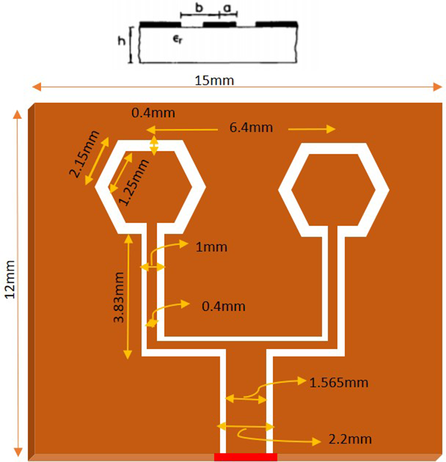
Fig. 3. 1×2 CPW hexagonal patch array antenna.
1×4 CPW hexagonal patch array antenna
The hexagonal patch elements are spaced 1.6 times the wavelength apart to maintain the proper wavelength gap between the CPW feed transmission line and radiating hexagonal patch. To maintain radiating patch impedance values real, a characteristic impedance of 50 ohms is assumed at the input feed line. Out of different array formats, parallel feed configurations have the broadest bandwidth when compared to a conventional single-element array and also it has the effect of cancellation of unwanted reflected powers within the feed network [Reference Ponchak, Tentzeris and Katehi14]. The extension of arrays has been evolving into a four-element antenna to achieve a good return loss at required resonating frequencies like 28 GHz with considerable gain and bandwidth as shown in Fig. 4.

Fig. 4. 1×4 CPW hexagonal patch array antenna.
4×4 CPW series fed hexagonal patch array antenna
Figure 4 shows the 1×4 patch array or four-element array antenna which uses the same dimensions of 1×2 patch array antenna and duplication is made next to the existing structure and both the structures are joined by the equal width corporate feed network. The difference between the hexagonal patches is maintained by 1.6λ g [Reference Yuan, Yuan and Li15]. A series feed antenna is implemented to increase the number from 4 to 16 using the microstrip feed line. An equivalent circuit for the proposed novel series fed array is easily constructed and is given in Fig. 5. The series feed hexagonal array consists of shunt impedance represented by patches connected with microstrip line and is proposed by an equivalent circuit as shown above. The total impedance of antenna structure is evaluated by single antenna impedance divided by the total number of elements, i.e. 4.
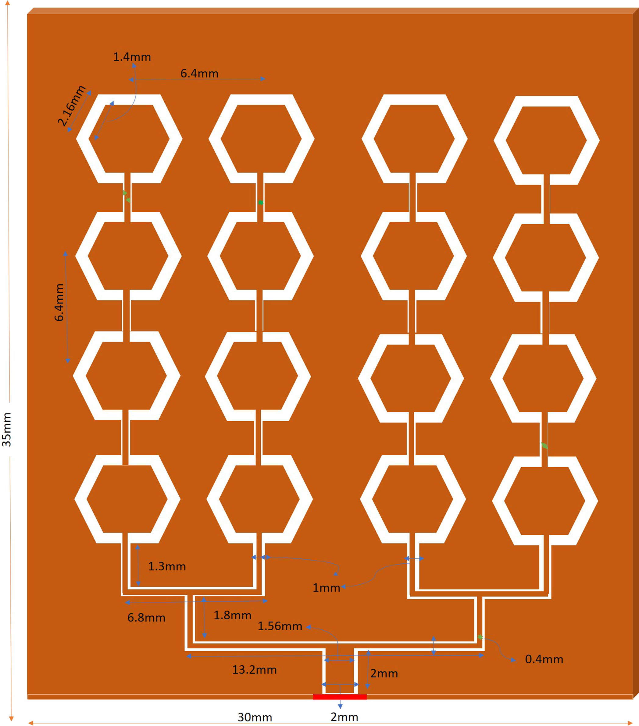
Fig. 5. 4×4 CPW series fed hexagonal patch array antenna.
To adjust different feed lines and patches in the proposed array antenna, a parametric analysis is performed to make an antenna resonate 28 GHz with maximum FBW. The analysis is performed on a single-element hexagonal patch antenna, 1×2, 1×4, and 4×4 series fed, CPW fed hexagonal patch array antennas and presented in the following section “Simulated results and discussions”.
Simulated results and discussions
The simulation of the proposed CPW hexagonal patch antennas is carried out in ANSYS HFSS 19 version tool. The performance of the millimeter-wave hexagonal antenna is assessed in terms of reflection coefficient, gain, radiation characteristics, efficiency, F/B ratio, and FBW which describes the wideband of the antenna The impedance mismatch is represented by the reflection coefficient at the load.
Single-element CPW fed hexagonal patch
The single-element CPW fed hexagonal patch antenna has radiated at a single frequency 28 GHz with a reflection coefficient of −24.21 dB but with a considerable fractional impedance bandwidth of 10.06% as shown in Fig. 6.

Fig. 6. The reflection coefficient of single-element hexagonal patch antenna.
According to the TRAI report, most of the millimeter-wave frequencies are considered from the 20–40 GHz range. But from the literature of millimeter-wave communications, the antennas required for 5 G frequency bands are allowed to work at fixed frequencies such as 28/38 GHz [Reference Ghione and Naldi16]. In that particular context, CPW feed hexagonal antennas are proposed. The reflection coefficient (S 11 in dB) versus frequency plot indicates that is a single resonant frequency band existing from 26.80 to 29.64 GHz with high gain and efficiency values as 4 dBi and 102%.
The radiation patterns for the proposed hexagonal antenna at mm-wave frequencies such as 28 GHz are in both horizontal (XY-plane) and vertical planes (YZ-planes). The maximum gain of 4.7 dB is achieved at θ = 00, −1800, and φ = 00 in E-plane, and in H-plane (φ = 900 ), the maximum gain of 5 dBi is attained at all directions at 28 GHz as shown in Fig. 7.

Fig. 7. 3D polar plot and radiation pattern of single-element hexagonal patch antenna.
1×2 CPW fed hexagonal patch array antenna
The reflection coefficient value of 1×2 CPW fed hexagonal patch antenna at resonant frequency 28 GHz existing from 25.88 to 28.93 GHz is −16.24 dB with high gain and efficiency values as 7.7 dBi and 102%. There is an increase in FBW value from 12.06 to 11.12% which has become the advantage in the choosing array concept as shown in Fig. 8.

Fig. 8. The reflection coefficient of 1×2 CPW fed hexagonal patch array antenna.
The radiation patterns for the proposed 1×2 hexagonal patch antenna at an mm-wave frequency such as 28 GHz are evaluated in both horizontal (XY-plane) and vertical planes (YZ-planes). It is observed from the figures that the radiation pattern at φ = 00 (E-plane) and θ = −300 has a maximum gain of 7.7×dBi and φ = 900 (H-plane) and θ = 00has a maximum gain of 4.9 dBi as shown in Fig. 9.

Fig. 9. 3D polar plot and radiation pattern of 1×2 CPW fed hexagonal patch array antenna.
1×4 CPW fed hexagonal patch array antenna
The 1×4 CPW fed hexagonal patch array antenna resonates at two particular frequency bands but the first frequency band is not considered for evaluation and the second band is considered which range from 27.73 to 30 GHz with a FBW of 10.49% which is high when compared to 1×2 CPW fed array antenna. The reflection coefficient value at 28 GHz is −11.64 dB which means the radiated power is less when compared to the 1×2 array antenna but is an acceptable value for practical purpose millimeter-wave antenna as shown in Fig. 10.

Fig. 10. The reflection coefficient of 1×4 CPW fed hexagonal patch array antenna.
The radiation patterns for the proposed 1×4 hexagonal patch antenna at 28 GHz are evaluated in both horizontal (XY-plane) and vertical planes (YZ-planes). It is observed from the figures that the radiation pattern at φ = 900 (H-plane) has maximum radiated power at four different directionssuch as θ = 300,−400,−1400, and 1500 and has an average value of 7.7 dBi, and at φ = 00 (E-plane) and θ = −300 to −1400, it has a maximum gain of 2 dBi as shown in Fig. 11.

Fig. 11. 3D polar plot and radiation pattern of 1×4 CPW fed hexagonal patch array antenna.
4×4 CPW series fed hexagonal patch array antenna
A detailed analysis is executed on the 4×4 CPW series fed hexagonal patch array antenna which includes the measurement of reflection coefficient, VSWR, 3 dB gain, radiation characteristics, and axial ratio. This particular antenna is considered for fabrication since it has wide band characteristics at 28 GHz which is considered as the resonating frequency for 5 G communications. According to the TRAI report, the most preferable millimeter-wave frequency is 28 GHz. The reflection coefficient (S 11 in dB) versus frequency plot indicates that multiple frequency bands exist with high impedance bandwidth and efficiency. The reflection coefficient values are observed as −14.13 dB at resonating frequency 28 GHz as shown in Fig. 12. The FBW is evaluated at a frequency from 25.52 to 30 GHz where the value is about 16.09%. The proposed 4×4 series fed CPW hexagonal array antenna has VSWR values as 1.49 at resonating frequencies such as 28 GHz.
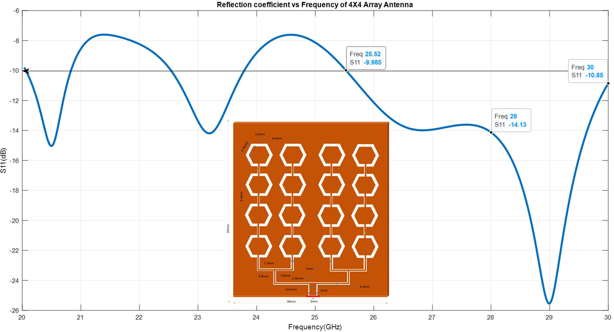
Fig. 12. Reflection coefficient of 4×4 CPW series fed hexagonal patch array antenna.
The 3D gain plots of three different array antennas start to increase as the number of patch elements increases at 28 GHz. It is observed from the figures that the radiation pattern at φ = 900 (H-plane) has maximum radiated power at different directions such as θ = 300, −300, −600, −1200, 1500, 1200, and 600 and has an average value of 9 dBi, and at φ = 00 (E-plane) and θ = −300 to 300 and −1500 to 1500, it has a maximum gain of 2 dBi as shown in Fig. 13. All the simulated values of the CPW array antennas are tabulated in Table 1.

Fig. 13. 3D polar plot and radiation pattern of 4×4 CPW series fed hexagonal patch array antenna.
Table 1. Comparison of different CPW array antennas simulated results

Measured results
The fabricated prototype of 4×4 CPW series fed hexagonal patch array antenna is made using PCB technology. As the proposed antenna consists of a CPW feed, there is no ground (copper) at the bottom side of the antenna which has been described in Fig. 14.

Fig. 14. The fabricated prototype of 4×4 CPW series fed hexagonal patch array antenna. (a) Top layer. (b) Bottom layer.
The 4×4 CPW series fed hexagonal patch array antenna is fabricated using Rogers RT5880 (lossy) substrate, with a height of 0.508 mm. A 2.92 mm connector is used where regular SMA connectors are not valid for this millimeter-wave frequency range [Reference Sulyman, Nassar, Samimi, MacCartney, Rappaport and Alsanie17]. The Agilent Technologies N5247A 67 GHz Vector Network Analyzer (VNA) is used for the measurement of reflection coefficient and VSWR parameters [18]. The VNA setup with the proposed array antenna is as shown in Fig. 15. The S 11(dB) versus frequency plots were varying based on the position of the antenna concerning VNA. The best suitable plot is considered for better performance analysis.

Fig. 15. The fabricated prototype of 4×4 CPW series fed hexagonal patch array antenna test setup at Vector Network Analyzer.
The measured reflection coefficient (S 11 in dB) versus frequency plot indicates that there is a wide frequency band that exists with moderate S 11(dB) values at 28 GHz [19–Reference Harini, Sairam and Madhu22]. The reflection coefficient values are observed as −31.02 dB at resonating frequency 28 GHz as shown in Fig. 16.

Fig. 16. Measured reflection coefficient of 4×4CPW series fed hexagonal patch array antenna.
The proposed 4×4 CPW series fed hexagonal patch array antenna has measured the VSWR values of 1.058 at a resonating frequency of 28 GHz as shown in Fig. 17.

Fig. 17. Measured VSWR of 4×4 CPW series fed hexagonal patch array antenna.
There is a sensible arrangement among simulated and measured results as shown in Figs. 18 and 19. The trend has been followed by a reduction in frequency bandwidth at the 28 GHz range. The variation may be due to fabrication errors and tolerances and the measured result is better than a simulated one in terms of reflection coefficient values [Reference Harini, Sairam and Madhu23,Reference Zhang, Jin, Wang, Pu, Li, Zhao, Gao, Wang and Luo24].

Fig. 18. Comparison of reflection coefficients of both simulated and measured results of 4×4 CPW series fed hexagonal patch array antenna.

Fig. 19. Comparison of VSWR of both simulated and measured results of 4×4 CPW series fed hexagonal patch array antenna.
Finally, the comparison of reflection coefficient values and VSWR of both simulated and measured results in dB is tabulated in Table 2. The measured values of reflection coefficient and VSWR values are improved when compared to a simulated one.
Table 2. Comparison of the proposed antenna simulated versus measured results

The comparison table of proposed antenna characteristics with existing antennas is mentioned below in Table 3.
Table 3. Comparison of proposed antenna characteristics with existing antennas

Conclusions
A 28 GHz CPW series fed millimeter-wave hexagonal array antenna is designed and analyzed with the different numbers of antenna elements such as single-element, 1×2, 1×4, and 4×4 antenna arrays. A detailed analysis is performed on the 4×4 array antenna and results concerning simulated versus measured were discussed in detail. It is described that the proposed array antenna is radiated at a single frequency band such as 28 GHz with a high gain of 8.98 dBi, and almost 102% efficiency. The 16-element array antenna attained a maximum FBW of 7% which is comparable when measured in VNA. The incorporation of CPW in the proposed antenna has achieved maximum FBW at 28 GHz where it can be integrated into any type of femtocells that are mostly used for future 5 G-based indoor communications due to the compact size.
 Harini V. is pursuing Ph.D. degree in Antennas from JNTUK, Kakinada, Andhra Pradesh, India. She is currently working as an Assistant Professor in the Department of ECE, Vardhaman College of EngineeringHyderabad. She received B.Tech degree in ECE from JNTU Hyderabad, Telangana, in 2008 and M.Tech degree in Communication Engineering from VIT University, Vellore, Tamil Nadu, India in 2010. Her research areas include wireless communications, 5 G communications, Femtocells, and millimeter-wave microstrip antennas and array antennas.
 Sairam M. V. S. is a Professor and Head, Department of Electronics and Communication Engineering at G. V. P. College of Engineering (Autonomous), Visakhapatnam, Andhra Pradesh, India. He received the B.E. degree from S. R. K. R. Engineering College (Affiliated to Andhra University), Bhimavaram, Andhra Pradesh in 1996, the M.E. degree from Andhra University, Visakhapatnam in 2002, and the Ph.D. degree from J. N. T. University, Kakinada, Andhra Pradesh in 2010. He is member of IEEE, IE, and ISTE. He has several publications in his area of expertise. His research interest includes wireless communications, digital signal processing, and error correcting codes, OFDM, and energy efficiency in cognitive radio.
 Madhu R. received the B.E. degree in Electronics & Communication Engineering from Osmania University, Hyderabad, India, in 2003, M.Tech degree in Communication Systems from Jawaharlal Nehru Technological University Hyderabad, India, in 2009, and Ph.D degree in Electronics & Communication Engineering from Andhra University, Visakhapatnam, India, in 2014. He is presently working as an Assistant Professor in the Department of Electronics & Communication Engineering, University College of Engineering Kakinada (A), JNTUK Kakinada, India. He has 10 years of teaching experience. He has published more than 30 research papers in various reputed national and international Journals and conferences. His research interests include mobile communications, satellite communications, and GPS. He is a member of IEEE.


