


1. Introduction
Stromatolites are laminated organo-sedimentary structures present in the geological record from 3.45 Ga, before the Cambrian explosion (Schopf, Reference Schopf1996; Grotzinger & Knoll, Reference Grotzinger and Knoll1999; Reid et al. Reference Reid, Visscher, Decho, Stolz, Bebout, Dupraz, Macintyre, Paerl, Pinckney, Prufert Beboult, Steepe and DesMarais2000; Allwood et al. Reference Allwood, Walter, Kamber, Marsahll and Burch2006). These structures are considered microbial in origin and represent one of the earliest evidence of benthic microbial communities on Earth (Grotzinger & Knoll, Reference Grotzinger and Knoll1999).
Stromatolites develop due to the complex interplay between biological (community structure) and environmental factors, such as exposure to water energy, water supply and drainage, input of clastic sediments and mineral precipitation rates (Golubic, Reference Golubic and Walter1976). However, near the coastline of peri-marine environments, the main extrinsic agents influencing the development of stromatolites are commonly related to wave intensity and tidal regimen (Logan et al. Reference Logan, Rezak and Ginsburg1964; Gebelein, Reference Gebelein and Walter1976; Andres & Reid, Reference Andres and Reid2006; Suosaari et al. Reference Suosaari, Reid, Araujo, Playford, Holley, Mc Namara and Eberli2016 a). Wave action and tidal oscillation control the accommodation space and, consequently, both the vertical and lateral distribution of stromatolites (e.g. Andres & Reid, Reference Andres and Reid2006; Kah et al. Reference Kah, Bartley, Frank and Lyons2006). Moreover, wave action and tidal oscillation influence both the external morphology (Dill et al. Reference Dill, Shinn, Jones, Kelly and Steinen1986; Reid & Browne, Reference Reid and Browne1991; Jahnert & Collins, Reference Jahnert and Collins2012) and the internal structure at various scales (Reid & Browne, Reference Reid and Browne1991; Suosaari et al. Reference Suosaari, Reid, Playford, Foster, Stolz, Casaburi and Eberli2016 b). The investigation of growth processes in fossil stromatolites is therefore a key element for reconstructing palaeoenvironmental conditions during their formation and development.
The Maastrichtian–Danian Yacoraite Formation (Turner, Reference Turner1959) represents a carbonate deposit widely distributed in northwestern Argentina and is an excellent marker horizon in the Salta Group. The main lithology of the formation is carbonate–calcareous and dolomitic, but it also contains shale and sandstone (Marquillas et al. Reference Marquillas, del Papa and Sabino2005; Sánchez & Marquillas, Reference Sánchez and Marquillas2010; Deschamps et al. Reference Deschamps, Rohais, Hamon and Gasparrini2020). The Yacoraite Formation constitutes an epicontinental unit widely exposed in northwestern Argentina (Marquillas et al. Reference Marquillas, del Papa and Sabino2005).
Stromatolites (microbialites) from the Yacoraite Formation were first reported in the late nineteenth century. Brackebusch (Reference Brackebusch1883) mentioned the presence of domic stromatolites (‘Pucalithus’), considered equivalent to the structures called ‘calcaire ondulée’ by d’Orbigny (Reference d’Orbigny1842) in the Cretaceous strata of Bolivia. Over the years, several stromatolite deposits have been recognized from this geological unit, but only mentioned or briefly described and discussed in a regional palaeoenvironmental and sedimentological context (e.g. Marquillas, Reference Marquillas1984, Reference Marquillas1985; Palma, Reference Palma1984; Marquillas & Salfity, Reference Marquillas and Salfity1989, Reference Marquillas and Salfity1994; Marquillas et al. Reference Marquillas, del Papa, Sabino and Heredia2003, Reference Marquillas, del Papa and Sabino2005; Cónsole-Gonella et al. Reference Cónsole-Gonella, de Valais, Sánchez and Marquillas2012, Reference Cónsole-Gonella, de Valais, Marquillas and Sánchez2017; Cónsole-Gonella & Marquillas, Reference Cónsole-Gonella and Marquillas2014; Bunevich et al. Reference Bunevich, Borghi, Gabaglia, Terra, Freire, Lykawka and Fragoso2017; Gomes et al. Reference Gomes, Bunevich, Tonietto, Alves, Santos and Whitaker2019; Deschamps et al. Reference Deschamps, Rohais, Hamon and Gasparrini2020).
Different stromatolitic morphologies were reported from intertidal facies of the Yacoraite Formation, such as isolated oncoids, planar-laminated stromatolites, isolated nodular stromatolites and moustache-like stromatolites (Hamon et al. Reference Hamon, Rohais, Deschamps and Gasparrini2012).
An excellent case study is represented by the shoreline carbonate lagoon deposits of Maimará locality, where three-dimensional (3D) preserved stromatolites are exposed. These stromatolites belong to facies classified as stromatolitic boundstone, in which they are related to siltstones, pelite layer, wackestone and erosive surfaces. Within this facies, hemispheroidal domes and semicircular dome morphologies were recognized. These levels have developed in a subtidal and/or lower intertidal to intertidal palaeoenvironment, with areas proximal to and more distant from the coastline, under wave and tide action and with variable depth and/or energy stages, as suggested by facies analysis (Cónsole-Gonella et al. Reference Cónsole-Gonella, de Valais, Marquillas and Sánchez2017).
The main goal of this contribution is to characterize in detail the relationships between this stromatolite system and hydrodynamic factors, in order to reconstruct in detail the palaeoenvironment.
2. Geological context
The Yacoraite Formation belongs to the Balbuena Subgroup (Upper Cretaceous–lower Paleocene), which is the early post-rift unit of the Salta Group (Lower Cretaceous–Eocene), an intracontinental rift-type basin (e.g. Salfity & Marquillas, Reference Salfity, Marquillas and Salfity1994; Marquillas et al. Reference Marquillas, del Papa and Sabino2005). This basin is associated with a tectonic regional context of extensional type in NW Argentina, which is common in basins of similar age in the Central Andes and nearby regions (Marquillas et al. Reference Marquillas, Salfity, Matthews, Matteini and Dantas2011). The Salta Group is represented in seven sub-basins of Salta and Jujuy provinces, Argentina, namely Tres Cruces, Lomas de Olmedo, Metán, Alemanía (Reyes, Reference Reyes1972), El Rey (Salfity, Reference Salfity1980), Sey (Schwab, Reference Schwab1984) and Brealito (Sabino, Reference Sabino2002).
The Yacoraite Formation comprises the Cretaceous–Palaeogene (K-Pg) boundary, as indicated by the varying stratigraphy. In the Metán sub-basin (Salta province), the unit is Maastrichtian in age as indicated by U-Pb radiometric dating (Marquillas et al. Reference Marquillas, Salfity, Matthews, Matteini and Dantas2011) of rock samples several metres below the top. In the Maimará locality, Sial et al. (Reference Sial, Ferreira, Toselli, Parada, Aceñolaza, Pimentel and Alonso2001) identified the K-Pg boundary, although its position in the stratigraphical section is not indicated. However, the overlying Tunal Formation is dated as Danian in age based on palynomorphs (Quattrocchio et al. Reference Quattrocchio, Ruiz and Volkheimer2000). On the basis of these data, the stromatolite levels within the Yacoraite Formation are interpreted as Maastrichtian in age, in a stratigraphic position likely close to the K-Pg boundary.
In the Maimará locality, the fossil record of the Yacoraite Formation is made up of gastropods, ostracods, fish remains, vertebrate tracks, invertebrate trace fossils, microbialites (Díaz-Martínez et al. Reference Díaz-Martínez, de Valais and Cónsole-Gonella2016; Cónsole-Gonella et al. Reference Cónsole-Gonella, de Valais, Marquillas and Sánchez2017), and palynomorphs (Moroni, Reference Moroni1984). The studied stratigraphic section records a lagoon palaeoenvironment with tidal influence associated with supratidal bodies of ephemeral ponds, described by Cónsole-Gonella et al. (Reference Cónsole-Gonella, de Valais, Marquillas and Sánchez2017).
2.a. Stratigraphy
The studied outcrop (23° 37ʼ 30.92ʼʼ S, 65° 23ʼ 56.07ʼʼ W) is located at the Maimará locality, SE of the Quebrada de Humahuaca, Jujuy province (Fig. 1). Palaeogeographically, the area belongs to the austral sector of the Tres Cruces sub-basin, close to the Salta–Jujuy ridge, which confers basin edge features on the deposit and distinguishes it from the austral sectors of the Salta Group basin (see Salfity & Marquillas, Reference Salfity, Marquillas and Salfity1994; Marquillas et al. Reference Marquillas, del Papa and Sabino2005).

Fig. 1. Geographical location of the Maimará site. Modified from Cónsole-Gonella et al. (Reference Cónsole-Gonella, de Valais, Marquillas and Sánchez2017). (a) Political map of Argentina, South America. Grey rectangle indicates the location of (b). (b) Political map of northwestern Argentina. The grey rectangle indicates the location of (c). (c) Map of the Quebrada de Humahuaca, Jujuy province, displaying the location of the Maimará site (grey rectangle).
The Balbuena Subgroup (Maastrichtian–Danian) lies unconformably above the quartz sandstones of the Mesón Group (middle–upper Cambrian) and it is represented by the Lecho Formation (Maastrichtian) and the Yacoraite Formation (Maastrichtian–Danian) (Cónsole-Gonella et al. Reference Cónsole-Gonella, de Valais, Marquillas and Sánchez2017) (Fig. 2). In the studied section, the Lecho Formation is represented by averaging 3 m of coarse to fine sandstones and angular, poorly sorted conglomerates immersed in a silty/sandy clay matrix, interpreted as the product of debris flows in a probably alluvial fan environment, with sparse water supply (Cónsole-Gonella et al. Reference Cónsole-Gonella, de Valais, Marquillas and Sánchez2017). Above, the Yacoraite Formation has an average thickness of 42 m (Figs. 3, 4a) and is represented by tabular, well-stratified, fossiliferous limestones and calcareous sandstones, with thin intercalations of laminate mudstones and stromatolite levels (Cónsole-Gonella et al. Reference Cónsole-Gonella, de Valais, Marquillas and Sánchez2017).

Fig. 2. Geological setting and stratigraphy of the study area. 1, Puncoviscana Formation (upper Precambrian–lower Cambrian); 2, Mesón Group (middle–upper Cambrian); 3, Ordovician?; 4, Balbuena Subgroup (Lecho and Yacoraite formations; Maastrichtian–Danian); 5, 6, Maimará and Uquía formations (Neogene); 7, 8, Quaternary. The star indicates the location of the Maimará section. After Cónsole-Gonella et al. (Reference Cónsole-Gonella, de Valais, Marquillas and Sánchez2017).

Fig. 3. Drone view of the working area. Stromatolites are indicated by a yellow star.

Fig. 4. Stratigraphic column of the outcrop. (a) Integrated logged section in Maimará. Modified from Cónsole-Gonella et al. (Reference Cónsole-Gonella, de Valais, Marquillas and Sánchez2017). (b) Detailed logged section. The red arrow indicates the stromatolite level MNE5.
3. Methodology
The integrated section of the Balbuena Subgroup is based on Cónsole-Gonella et al. (Reference Cónsole-Gonella, de Valais, Marquillas and Sánchez2017) (Fig. 4a). The best preserved stromatolite level, which is the main object of this study, is MNE5 (Fig. 4b). Sedimentary structures, stratal geometry, boundaries, layering, thickness variations and fossil content were also described to build a detailed logged section. Ten samples were collected and currently housed in the Paleontología de Invertebrados Lillo collection (PIL17.150–17.160) of the Universidad Nacional de Tucumán (Argentina). Polished slabs and thin-sections were prepared, labelled and housed at the petrography laboratory of the Instituto Superior de Correlación Geológica (INSUGEO), Tucumán, Argentina (collection numbers PIL-MNE5-P and PIL-MNE5-T1–T5).
Stromatolites were described following a traditional multiscale approach (e.g. Preiss, Reference Preiss and Walter1976; Shapiro, Reference Shapiro2000; Vennin et al. Reference Vennin, Olivier, Brayard, Bour, Thomazo, Scarguel, Fara, Bylund, Jenks, Stephen and Hofmann2015), focused on the separate characterization of the megastructure (i.e. large-scale features of microbialite bed), macrostructure (i.e. gross form of microbialite bodies with typical dimensions of tens of centimetres to metres), mesostructure (i.e. internal textures of macrostructural elements visible to the naked eye) and microstructure (i.e. microscopic fabrics observed under petrographic analysis).
The external morphology and architecture of stromatolites was determined on the basis of field and laboratory data, including dimensions and spatial distribution, overall external appearance, colour, types of contacts and stratal thicknesses. The description is based on the proposals by Cumings (Reference Cumings1932), Clarke & Teichert (Reference Clarke and Teichert1946), Logan (Reference Logan1961), Aitken (Reference Aitken1967) and Gebelein (Reference Gebelein and Walter1976). More recent concepts discussed by Davaud et al. (Reference Davaud, Strasser and Jedoui1994), Nehza & Woo (Reference Nehza and Woo2006), Forbes et al. (Reference Forbes, Vogwill and Onton2010), Jahnert & Collins (Reference Jahnert and Collins2012), Cooper et al. (Reference Cooper, Smith and Arnscheidt2013), Perissinotto et al. (Reference Perissinotto, Bornman, Steyn, Miranda, Dorrington, Matcher and Peer2014), Suosaari et al. (Reference Suosaari, Reid, Playford, Foster, Stolz, Casaburi and Eberli2016 b) and Edwards et al. (Reference Edwards, Anderson, Perissinotto and Rishworth2017) were also considered.
High-resolution digital photogrammetry was used to obtain a reliable representation of the 3D stromatolite external morphology and architecture. A close-range photogrammetric survey was conducted, and 442 images were selected to achieve a good image overlap. Images were acquired using a 24-megapixel reflex digital camera with 27 mm focal length (43.2 mm equivalent) and pixel size 3.84 × 3.84 μm. A 3D textured mesh was generated by the software Agisoft Metashape Pro (version 1.5.2, Educational License). To correctly scale the model, a set of metric reference markers was used. The 3D model was converted to a false-colour topographic map using the software Paraview (version 5.4.1) (Figs. 5, 6b). The tidal reconstructions (see also online Supplementary Material S1 and S2, available at http://journals.cambridge.org/geo) were designed using the software Blender (version 2.81).

Fig. 5. 3D model of the outcrop obtained with digital photogrammetry. (a) Orthomosaic of the whole stromatolite outcrop. The white dotted area indicates the best preserved group of clusters. (b) Orthomosaic delimited within the highlighted area of (a). (c) Elevation model of (b). The figure show ten fully exposed clusters, four partially covered clusters and more than ten individual domes. Palaeosurface of sedimentation is represented with blue colorimeters. The numbers indicate the position of the clusters and domes with respect to Fig. 6b.

Fig. 6. Channel reconstruction. (a) Channel classification by order and relative dimensions at section view of clusters. (b) 3D photogrammetric elevation model of best preserved clusters. First-order channels are indicated with white lines, second-order channels with red lines. The numbers indicate the cluster position in Figure 5c.
Internal morphology of stromatolites was described using polished slabs and thin-sections in the laboratory. The macrostructure and mesostructure were described using the classification proposed by Logan et al. (Reference Logan, Rezak and Ginsburg1964) and Horodyski (Reference Horodyski1977). We use the following abbreviations sensu Logan et al. (Reference Logan, Rezak and Ginsburg1964) in the text: SH-C – internal structure of hemispheroids vertically stacked with a constant basal radius; SH-V – internal structure of hemispheroids vertically stacked with a variable basal radius; and LLH-C – internal structure of closed laterally linked hemispheroids. In analysing microstructure, we focused on different parameters such as lamination types, stacking patterns of laminae, lateral and vertical continuity of lamination, growth dynamics, hiatuses and/or disruptions in laminae, among others. Tidal channels were assessed and discussed adopting some concepts by Sarjeant (Reference Sarjeant and Frey1975). Laminae were described based on their composition, lateral continuity, thicknesses and geometrical arrangement. Study of erosional structures was based on the criteria of Schneider (Reference Schneider and Flügel1977), Scholle (Reference Scholle1978) and Cevallos-Ferriz & Werber (Reference Cevallos-Ferriz and Werber1980).
The percentage of porosity was estimated by point counting and its analysis was based on the classification proposed by Choquette & Pray (Reference Choquette and Pray1970) and the descriptive and genetics concepts of Alonso et al. (Reference Alonso, Esbert and Ordaz1987) and Ahr et al. (Reference Ahr, Mancini and Parcell2011). The description of the carbonates was carried out using the scheme proposed by Folk (Reference Folk1959) and Kendall et al. (Reference Kendall, Flood, Hopley and Hopley2011).
4. Results
4.a. Overall depositional architecture and external morphology
The analysed level MNE5 ranges over 100–125 cm in thickness (Figs. 4b, 5a). MNE5 level is made up of stromatolitic domes with diameters ranging from 60 to 150 cm (Fig. 5a, b), forming a bioherm megastructure. The domes are distributed in three different groups according to their heights: the smallest (40–45 cm), a second group (45–55 cm), and the more developed (55–70 cm) (Fig. 5c). All the stromatolites are on the top of the same palaeosurface of sedimentation (calcareous sandstone layer), where some depressions are observed (Fig. 5c).
Stromatolites occur as isolated domes or are organized in clusters of domes (Fig. 5a–c). The isolated domes are scarcer and smaller, with diameters ranging from 30 to 50 cm and heights less than 45 cm (Fig. 5c). The clusters are delimited by channels up to the lower middle tier surface (in green colours). Cluster exhibits up to five domes ranging from 40 to 65 cm in height, extending over areas up to 10 m2. There are ten fully exposed clusters, although the other four clusters are partially covered by the overlying shale layers (Fig. 5c; online Supplementary Fig. S1a, available at http://journals.cambridge.org/geo).
The 3D elevation model shows that the middle tier cluster (in green colours) forms elongated structures with preferred orientation in the E–W direction, mainly ESE–WNW direction (Fig. 5c; online Supplementary Fig. S1a). Sometimes, these elongated structures can approach or even coalesce laterally along the length of the rows, producing compound masses with elongation normal to that of the primary elongation. In the top tier (in orange and reddish colours), the clusters acquire more symmetrical domic shapes (Fig. 5c; online Supplementary Fig. S1a).
Both stromatolite clusters and individual domes are characterized by the occurrence of multiscale arrangement of channels (first, second and third order) (Fig. 6a). First-order channels refer to passages ranging from 30 to 100 cm in width and showing straight organization. As for the elongation of the middle tier clusters, these channels are aligned in the ESE–WNW direction (online Supplementary Fig. S1b). Second-order channels have an average of 20 cm width, separate domes within clusters and connect first-order channels to each other, adapting their morphology to the space between domes (Fig. 6b).
MNE5 stromatolites show a hemispheroidal external morphology (Fig. 7a), where the lateral development is greater than the vertical development (Fig. 7b, c). The external surface of the stromatolites is irregular, composed of small crests (diameters from 0.2 to 1 cm) and is lined with cavities filled with sediments. These cavities, referred to as third-order channels (Figs. 6a, 7d), give the domes a ‘cerebroid’ appearance (e.g. Pratt & James, Reference Pratt and James1982).
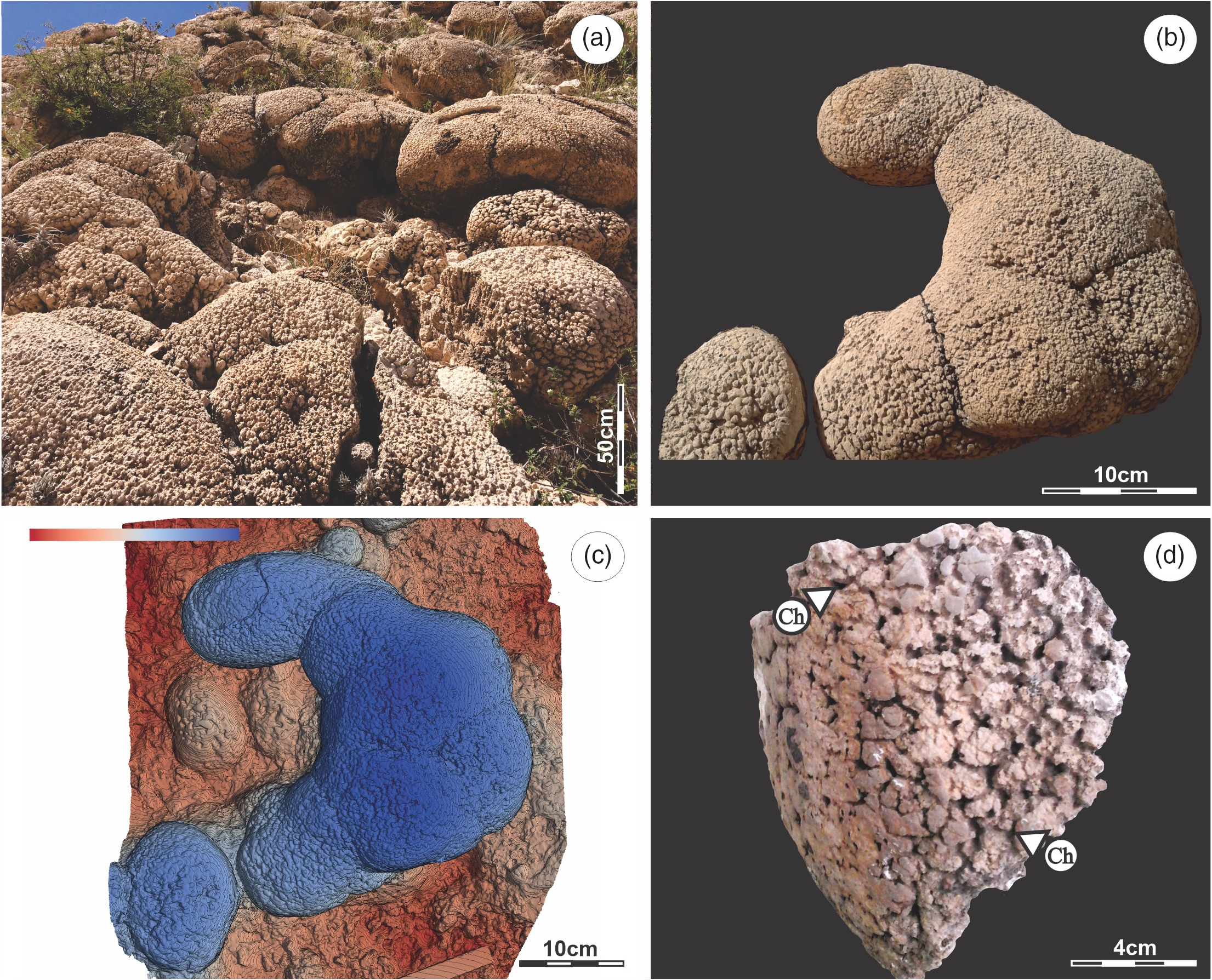
Fig. 7. External morphology and appearance. (a) Outcropping view of stromatolites. (b, c) Photography and 3D topography reconstruction of a cluster. The basal substratum and small domes are indicated by red, and well developed domes integrating the cluster are highlighted in blue. (d) Detailed view of the cerebroid surface appearance of a stromatolite dome. Cavities filled with sediments are called third-order channels (Ch).
4.b. Internal morphology
Stromatolites exhibit a highly convex growth profile. The internal morphology is almost homogeneous, prevailing laminated columnar structures, which allows to describe an internal structure as a type columnar with branch (sensu Horodyski, Reference Horodyski1977) (Fig. 8a). However, a basal sector (up to c. 3 cm in height) without a defined internal structure and the presence of isolated laminae is observed while, in the more developed domes, the top (in the last c. 3 cm) shows continuous lamination (Fig. 8a).
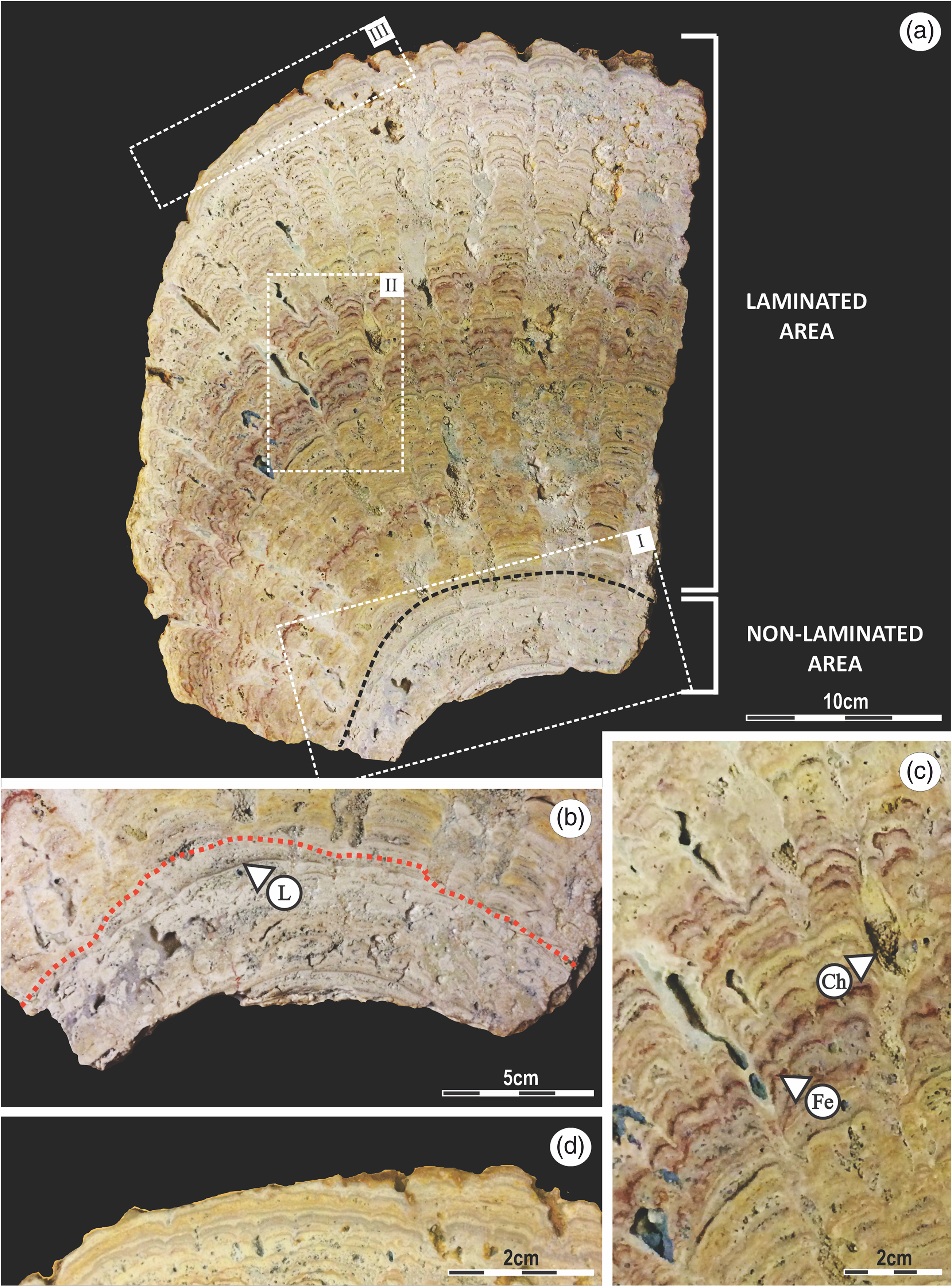
Fig. 8. Polished section (collection code: PIL 17.150, sample code: MNE5-P). (a) Two areas with different lamination patterns can be observed: there is a non-laminated area at the base, while from the middle to the top the structure is laminated. (b) Area I of the basal sector. Interrupted lamination (L) in a sparite matrix. (c) Area II of a SH mesostructure. Column structures are separated by third-order channels (Ch). Laminae with ferrous tonalities (Fe). (d) Area III of a LLH-C mesostructure.
4.b.1. Mesostructure
The basal sector (up to c. 3 cm in height) is composed of uniform micrite, with the minor presence of well-developed, up to 1-mm–thick, laminae, isolated and interrupted throughout their lateral development (Fig. 8a, b). The rest of the dome exhibits an internal geometry of SH type, displaying laminated columns of both mode C and mode V. The SH-C structures are more common in the central and upper part of domes, while the SH-V are more common at the base and along flanks (Fig. 8a–c). Some columns are joined together at the top of domes (the last c. 3 cm) with a height greater than 55 cm, giving rise to the internal morphologies of LLH-C type (Fig. 8d).
Columns are developed with widths ranging from 0.3 to 2.5 cm. Some columns display upwards-developing branches with smaller-diameter (0.1 cm) columns. The laminae composing the columnar structures, up to 1 mm thick, are convex upwards and the edges of the columns are coalescent (Fig. 8c). Inside columns, random laminae with ferrous tonalities (Fig. 8c) and laminae with ooids (online Supplementary Fig. S2) can be observed (see Section 4.b.2).
The columns are separated from each other by third-order channels. These channels are cavities of variable width (0.1–0.8 cm) with irregular edges. The development plane of these cavities is perpendicular to the lamination. Third-order channels are filled with clastic material immersed in a micritic matrix, and are discussed in the following section (Fig. 8c).
4.b.2. Microstructure
Microstructure is characterized by the alternation of dark dense micritic laminae with lighter micritic to microsparitic laminae, giving rise an alternating simple lamination (sensu Monty, Reference Monty and Walter1976) (Fig. 9a, b). Dark laminae have an average thickness of 0.5 mm, and lighter laminae have an average thickness of 0.4 mm. Both dark dense micritic laminae and lighter micritic to microsparitic laminae present close texture, diffuse boundaries and transitional contacts (Fig. 9a, b). In some sectors there are a few sparitic laminae, up to 0.3 mm in thickness (which usually remains constant), with good lateral continuity, slight sinuosity and a fibrous texture (Fig. 9c).

Fig. 9. Collection code: PIL 17.165. (a, b) Alternating dark dense micritic laminae (Md) with lighter micritic (Ml) to microsparitic laminae. The laminae are poor in intraclasts, with close texture, diffuse boundaries and transitional contact. (c, d) Thin-section MNE5-T1: (c) isolated lamina of sparitic composition (S) with slight sinuosity and fibrous texture; (d) ferrous levels (Fe) with a thickness of < 0.1 mm, interrupted laterally and retracted. (e, f) Thin-section MNE5-T5: laminae with clastic material composed of ooids (light blue circles), semi-rounded micritic intraclasts and lithic fragments.
Ferrous levels are also observed with a thickness of less than 0.1 mm, interrupted laterally and retracted (Fig. 9d). In addition to this, random laminae with clastic material also stand out (up to 1 mm in thickness) (Fig. 9e, f). They are composed of ooids (up to 0.4 mm diameter), semi-rounded micritic intraclasts (up to 0.2 mm diameter) and lithic fragments (up to 0.2 mm diameter) (Fig. 9e, f).
Throughout the microstructure, the lamination is interrupted by the third-order channels ranging from 1 to 8 mm in diameter (Fig. 10a). They have sinuous and irregular edges, and a direction of development perpendicular to the lamination plane. The lamination upon reaching this cavity curves downwards, onlapping each other (Fig. 10b). Third-order channels are filled with a micrite matrix with the main presence of ooids dispersed heterogeneously, semi-rounded micritic intraclasts (up to 1.5 mm diameter), quartz grains (up to 0.2 mm diameter) and ostracods (up to 0.8 mm diameter) (Fig. 10c), forming a packed biomicrite texture. Ooids are spherical and elliptical with a concentric pattern, and are up to 2 mm in diameter. The nuclei are composed of carbonate or quartz fragments. Common aragonitic alteration is observed at the outer edges (Fig. 10d).

Fig. 10. Collection code: PIL 17.165. (a, b) Thin-section MNE5-T2: (a) Cavities (third-order channels) interrupting the lamination. (b) Edges of the channels with an orientation of development perpendicular to the lamination plane. The lamination (red lines) deflects downward reaching the cavity. (c, d) Thin-section MNE5-T3: (c) third-order channels filled with oo-micritic material; Ostracods are indicated with red arrows; (d) Spherical ooid with detrital nuclei and concentric shape. (e, f) Thin-section MNE5-T4: (e) fenestral porosity (Fn): consists of irregular voids, horizontally elongate, and parallel to bedding with a thickness up to 0.25 mm; (f) Vacuolar porosity (P) (non-selective factory).
The estimated average porosity reaches a total of 36.20%. Two kinds of fenestral fabrics are observed: (1) irregular voids, horizontally elongate and parallel to bedding with a thickness of up to 0.25 mm (Fig. 10e) are the most abundant; and (2) bubble-like vugs, parallel to bedding with a thickness up to 0.3 mm. In addition to fenestral porosity, vacuolar, cavern and interparticle pore morphologies are also observed (Choquette & Pray, Reference Choquette and Pray1970) (Fig. 10f).
5. Discussion
Although the architecture of stromatolitic deposits can be conditioned by the microorganisms that produce them (van de Vijsel et al. Reference van de Vijsel, van Belzen, Bouma, van der Wal, Cusseddu, Purkis, Rietkerk and van de Koppel2020), the middle tier cluster and the first-order channels show a preferred orientation that suggest the influence of unidirectional hydrodynamic energy in an intertidal environment (Hoffman, Reference Hoffman and Ginsburg1973, Reference Hoffman and Walter1976 a, b; Reid & Browne, Reference Reid and Browne1991). Based on comparisons with modern analogues, elongated stromatolitic structures usually show preferred orientation parallel to water movement and with channels perpendicular to the coastline (Hoffman, Reference Hoffman and Ginsburg1973, Reference Hoffman and Walter1976 a, b; Reid & Browne, Reference Reid and Browne1991).
Isolated stromatolites and the upper parts of the clusters present domic external morphology. In modern analogues, dome forms are interpreted as a response to minimize hydrodynamic energy (e.g. Gebelein, Reference Gebelein1969; Dill et al. Reference Dill, Shinn, Jones, Kelly and Steinen1986; Andres & Reid, Reference Andres and Reid2006; Suosaari et al. Reference Suosaari, Reid, Playford, Foster, Stolz, Casaburi and Eberli2016 b); however, these forms also occur in restricted and partially restricted environments, such as lagoons or lakes (e.g. Reitner et al. Reference Reitner, Paul, Arp, Hause-Reitner, Reitner, Neuweiler and Gunkel1996; Cohen et al. Reference Cohen, Talbot, Awramik, Dettman and Abell1997; Grey & Planavsky, Reference Grey and Planavsky2009). Stromatolites studied here have similarities to those developing in environments of low hydrodynamic energy (e.g. Moore & Burne, Reference Moore, Burne and Casanova1994; Reitner et al. Reference Reitner, Paul, Arp, Hause-Reitner, Reitner, Neuweiler and Gunkel1996; Grey & Planavsky, Reference Grey and Planavsky2009; Wacey et al. Reference Wacey, Urosevic, Saunders and George2018) regarding external morphology and simple branching columns. At the same time, different orders of magnitude in hydrodynamics suggest a partially restricted environment but not entirely indifferent to the action of the waves and tide (Eckman et al. Reference Eckman, Andres, Marinelli, Bowlin, Reid, Aspden and Paterson2008; Arenas & Pomar, Reference Arenas and Pomar2010).
Accommodation space available for stromatolite growth and development is basically represented by water depth (vertical space) and substrate availability (lateral space). Vertical growth of domes is depth dependent (Kah et al. Reference Kah, Bartley, Frank and Lyons2006; Bergman et al. Reference Bergman, Westphal, Janson, Poiriez, Eberli, Westphal, Riegl and Eberti2010). As observed in current environments, different heights of domes present in the deposit indicate intervals of stability as the depth of the environment changes (e.g. Jahnert & Collins, Reference Jahnert and Collins2012; Suosaari et al. Reference Suosaari, Reid, Araujo, Playford, Holley, Mc Namara and Eberli2016 a). On the other hand, lateral development of stromatolites is controlled by substrate availability, which in turn is limited by the adjoining domes or by the channels of first and second order. Water run-off concentrates along these channels, preventing the lateral development of the stromatolites and favouring domic morphologies due to their reduced resistance to hydrodynamic conditions (Gebelein, Reference Gebelein1969).
The presence of depressions in the palaeosurface of sedimentation is probably related to erosive areas where the water swirls during the changing tides, where first-order channels connect (see Figs. 6c, 7b).
5.a. The influence of hydrodynamic conditions and factors in internal morphology
The internal structure is also a reflection of hydrodynamic conditions (Logan et al. Reference Logan, Rezak and Ginsburg1964; Aitken, Reference Aitken1967; Hoffman, Reference Hoffman and Ginsburg1973; Acosta et al. Reference Acosta, García Hernández and Checa1988). The columnar structures are probably a response to reduce energy conditions (Dupraz et al. Reference Dupraz, Pattisina and Verrecchia2006), although we cannot rule out the influence of biotic factors (von der Borch et al. Reference von der Borch, Bolton and Warren1977).
Dupraz et al. (Reference Dupraz, Pattisina and Verrecchia2006) suggested that the presence of columnar structures depends on a factor called ‘attraction distance’, which is a model of the attraction force of the build-up. An increase in the attraction distance leads to larger protection zones where no growth is possible and produces the formation of wider-spaced columnar or branching morphologies. The protection zones can be the result of differential erosive effects during water run-off through small escape routes (i.e. third-order channels), truncating the in vivo microbial mats growth (Schneider, Reference Schneider and Flügel1977; Cevallos-Ferriz & Werber, Reference Cevallos-Ferriz and Werber1980; Shapiro & Awramik, Reference Shapiro and Awramik2000). However, columnar structures can be found in stromatolites from restricted and partially restricted environments, where the filling of the third-order channel (ooids, micritic intraclasts and ostracods) confirm the influence of tides and waves in its development (Altermann, Reference Altermann2008).
Branching of the stromatolite columns may be due to changes in the sediment supply and/or a change in the composition of the microbial community (Planavsky & Grey, Reference Planavsky and Grey2008; Mackey et al. Reference Mackey, Summer, Hawes, Jungblut and Andersen2015). Although it is not possible to know precisely which of these two processes was predominant, branching appears to be closely related to a decrease in sediment supply, the product of an increase in depth that would have decreased hydrodynamic energy, resulting in more stable environmental conditions in which the microbially mediated framework growth began to control stromatolite morphology (Planavsky & Grey, Reference Planavsky and Grey2008; Mackey et al. Reference Mackey, Summer, Hawes, Jungblut and Andersen2015). The width of the columns was controlled by the accommodation space inside the stromatolite, which was limited by the third-order channels and domic morphology (Horodyski, Reference Horodyski1977).
The LLH-C structures located in the upper area of stromatolites can be explained as a reduction in the hydrodynamic energy of the system with respect to SH structures (Logan et al. Reference Logan, Rezak and Ginsburg1964; Dupraz et al. Reference Dupraz, Pattisina and Verrecchia2006). This energy reduction allows microbial mats to colonize the entire surface of the stromatolite, giving rise to a continuous laminar structure.
Laminated micrite/microsparite is interpreted as a primary depositional microstructure (Reid et al. Reference Reid, James, Macintyre, Dupraz and Burne2003). The predominance of this microstructure and the low content of clastic material in the lamination suggest that growth of stromatolites was controlled by the in situ precipitation of carbonate with the influence of microbial activity (Reid et al. Reference Reid, Visscher, Decho, Stolz, Bebout, Dupraz, Macintyre, Paerl, Pinckney, Prufert Beboult, Steepe and DesMarais2000). Alternation between micritic and microsparitic laminae is attributed to a variation in the predominance of nucleation and crystallization processes during the growth of the stromatolite (Riding, Reference Riding2000; Dupraz et al. Reference Dupraz, Reid, Braissant, Decho, Norman and Visscher2009). This can be produced by different factors, such as the hydrodynamic energy, changes in the precipitation rate, changes in saturation, level of organic activity, and/or fluctuation of carbonate and calcium concentration (Giuffre et al. Reference Giuffre, Hamm, Han, De Yoreo and Dove2013; Dobberschütz et al. Reference Dobberschütz, Nielsen, Sand, Civioci, Bovet, Stipp and Andersson2018; Li & Jun, Reference Li and Jun2019).
Although the stromatolites studied in this manuscript cannot be classified as ‘agglutinated stromatolites’ (sensu Riding et al. Reference Riding, Awramik, Winsborough, Griffin and Dill1991), laminae with clastic material (including ooids) developed when carbonate sand was remobilized by water currents and grains were trapped within the microbial mats. This suggests a pause in in situ precipitation of carbonate and a momentary predominance of trapping and binding (Suárez-González et al. Reference Suárez-González, Quijada, Benito, Mas, Merinero and Riding2014, Reference Suárez-González, Quijada, Benito, Mas, Tessier and Reynaud2016).
Conditions for ooid trapping by stromatolites may be preferentially achieved in tidally influenced environments, under shallow to very shallow water conditions. Constant grain availability in the environment is necessary to trap ooids and other carbonate particles, which is common in intertidal environments where grains were mobilized by tides in addition to waves and episodic storms (Suárez-González et al. Reference Suárez-González, Quijada, Benito, Mas, Tessier and Reynaud2016).
In the MNE5 stromatolites of Maimará, laminae with clastic material appear to be limited by two factors: (1) a decrease in sediment supply, the product of an increase in water level (Altermann, Reference Altermann2008); and (2) the size of the clasts (as observed in the channels) exceeding the thickness of the lamination, which complicates their capture (Riding et al. Reference Riding, Awramik, Winsborough, Griffin and Dill1991; Altermann, Reference Altermann2008).
Fenestral porosity has a depositional genesis product of two factors that can act separately or in combination: (1) retraction of the lamination, product of the desiccation; or (2) gas bubbles as a result of the decay of organic matter (Alonso et al. Reference Alonso, Esbert and Ordaz1987; Mazzullo, Reference Mazzullo2004; Sanz-Montero et al. Reference Sanz-Montero, Rodríguez-Aranda and Calvo2005). Several authors have suggested that fenestral porosity should be considered with certainty as indicative of upper intertidal to supratidal environments (Shinn, Reference Shinn1968, Reference Shinn1983; Chatalov, Reference Chatalov2009; Mata et al. Reference Mata, Harwood, Corsetti, Stork, Eilers, Berelson and Spear2012). Vughs, caverns and interparticle pores have a genesis influenced by dissolution during diagenesis (Ahr et al. Reference Ahr, Mancini and Parcell2011).
5.b. Interpretation of channels
Based on comparisons with modern and fossil analogues, channels are interpreted as the result of the differential modelling and erosive effect during the run-off of water by tides and waves, preventing the lateral continuity of the stromatolite (e.g. Hoffman, Reference Hoffman and Walter1976 a; Schneider, Reference Schneider and Flügel1977; Cevallos-Ferrix & Werber, Reference Cevallos-Ferriz and Werber1980; Acosta et al. Reference Acosta, García Hernández and Checa1988; Andres & Reid, Reference Andres and Reid2006; Jahnert & Collins, Reference Jahnert and Collins2012).
First-order channels (Figs. 5c, 6; online Supplementary Fig. 1b) represent areas with enhanced hydraulic stress (Cevallos-Ferriz & Werber, Reference Cevallos-Ferriz and Werber1980). As seen in analogous deposits, they tend to develop perpendicular to the coastline (i.e. parallel to the hydrodynamic direction) with a clear hydraulic tendency (Hoffman, Reference Hoffman and Walter1976 b; Reid & Browne, Reference Reid and Browne1991), suggesting that the tidal water and/or stream water transported through them achieved high hydrodynamic energy and prevented microbial development (Hoffman, Reference Hoffman and Walter1976 a; Andres & Reid, Reference Andres and Reid2006). These channels would also concentrate rip currents, acting along with the hydrodynamic energy in two directions, making it difficult to locate and orient the coastline.
On the other hand, second-order channels were formed in areas with lower hydraulic energy after the run-off, which limited the lateral development of stromatolite structures (Figs. 5c, 6).
Third-order channels are spaces where the passage of water truncates the microbial mats in vivo (see Schneider, Reference Schneider and Flügel1977; Cevallos-Ferriz & Werber, Reference Cevallos-Ferriz and Werber1980; Shapiro & Awramik, Reference Shapiro and Awramik2000) (Figs. 6a, 8c, 10a, b). As observed in extant analogues influenced by waves and tides (e.g. Gebelein, Reference Gebelein1969; Altermann et al. Reference Altermann, Kazmierczak, Oren and Wright2006), hydrodynamic energy acting along these channels prevents the formation of microbial mats, determining the development of a wedged and downwards-curved lamination.
Evidence indicating high-energy conditions is provided by the type of filling in the third-order channels, which occurs passively during the stromatolitic growth through the deposition of ooids. Concentric ooids with different nuclei and sizes, aragonitic alteration at the edges and heterogeneously distributed in the channels, suggest good agitation and transport through different energy pulses (Rohrlich, Reference Rohrlich1974; Scholle, Reference Scholle1978; Frakes & Bolton, Reference Frakes and Bolton1984).
Ostracods suggest partially restricted coastal areas, such as a lagoon (Palma, Reference Palma1993; Carignano & Ballent, Reference Carignano and Ballent2009). No evidence of bioturbation is observed in channel deposits or on their edges, and ostracods were not found in burrowing and grazing positions that suggest interaction with the stromatolites, so they are only considered para-autochthonous bioclasts.
5.c. Palaeoenvironmental model
The obtained results and the comparison with modern analogues allow to infer that the stromatolites from Maimará were developed in a lower intertidal to shallow subtidal environment close to the coastline (e.g. Hoffman, Reference Hoffman and Walter1976 a; Reid & Browne, Reference Reid and Browne1991; Dupraz et al. Reference Dupraz, Pattisina and Verrecchia2006; Jahnert & Collins, Reference Jahnert and Collins2012; Suosaari et al. Reference Suosaari, Reid, Playford, Foster, Stolz, Casaburi and Eberli2016 b). Indeed, outcrop architecture, clusters and channels distribution are quite similar to modern intertidal stromatolites of Shark Bay (Australia) (Hoffman, Reference Hoffman and Ginsburg1973, Reference Hoffman and Walter1976 b) and Stocking Island (Exuma Cays, Bahamas) (Reid & Browne, Reference Reid and Browne1991), and middle Precambrian intertidal stromatolites (Canadian Shield) (Hoffman, Reference Hoffman and Walter1976 a), in which main orientation is perpendicular to the shore and parallel to palaeocurrents, similar to our study case. This interpretation agrees with and reinforces the previous palaeoenvironmental proposal of Cónsole-Gonella et al. (Reference Cónsole-Gonella, de Valais, Marquillas and Sánchez2017, Reference Cónsole-Gonella, Díaz-Martínez, Citton and de Valais2021).
Some authors suggested the presence of stromatolites in lake systems in the southern sector of the basin (Metán–Alemanía sub-basin) (Bunevich et al. Reference Bunevich, Borghi, Gabaglia, Terra, Freire, Lykawka and Fragoso2017; Gomes et al. Reference Gomes, Bunevich, Tonietto, Alves, Santos and Whitaker2019; Deschamps et al. Reference Deschamps, Rohais, Hamon and Gasparrini2020). Given the size of the basin and its distance from Maimará locality (Tres Cruces sub-basin), it is accepted that this may be correct. However, tidal influence during deposition of the Yacoraite Formation in the southern sector of the Metán sub-basin (Cabra Corral locality, Salta province) was assessed by Marquillas et al. (Reference Marquillas, del Papa, Sabino and Heredia2003, Reference Marquillas, del Papa and Sabino2005) for the entire basin. In addition, stromatolite tidal deposits of the Yacoraite Formation were also recognized in Cabra Corral area by Hamon et al. (Reference Hamon, Rohais, Deschamps and Gasparrini2012) and Cónsole-Gonella & Marquillas (Reference Cónsole-Gonella and Marquillas2014). These authors described several stromatolite architectures related to restricted lagoon to tidal flat deposits (Hamon et al. Reference Hamon, Rohais, Deschamps and Gasparrini2012), consistent with the environmental setting proposed in our study section by Cónsole-Gonella et al. (Reference Cónsole-Gonella, de Valais, Marquillas and Sánchez2017).
The different heights reached by the domes are likely due to changes in water level, which controlled the upper limit of accommodation space (Kah et al. Reference Kah, Bartley, Frank and Lyons2006; Arenas & Pomar, Reference Arenas and Pomar2010; Bergman et al. Reference Bergman, Westphal, Janson, Poiriez, Eberli, Westphal, Riegl and Eberti2010). This information suggests an overall variation of water depth from 45 to > 70 cm, as observed in similar settings (e.g. Coorong Lagoon area in von der Borch, Reference von der Borch and Walter1974).
In such a changing environment (from lower intertidal to shallow subtidal), it is difficult to determine which hydrodynamic factor played a dominant role (i.e. waves or tides). In a first stage, the stromatolites developed in a lower intertidal environment in which water depth was progressively increasing (second stage) (Fig. 11). The preferred orientation of the middle tier cluster and first-order channels, the presence of ferrous laminae in the lower and middle zone of the domes, the filling of the third-order channels and the internal structure of the SH type all suggest an environment with the hydrodynamic energy controlled by both waves and run-off of the water during the low tide (Logan et al. Reference Logan, Rezak and Ginsburg1964; Hoffman, Reference Hoffman and Walter1976 a; Reid & Browne, Reference Reid and Browne1991) (Figs. 12, 13; online Supplementary Fig. S2 and Supplementary Material S1).
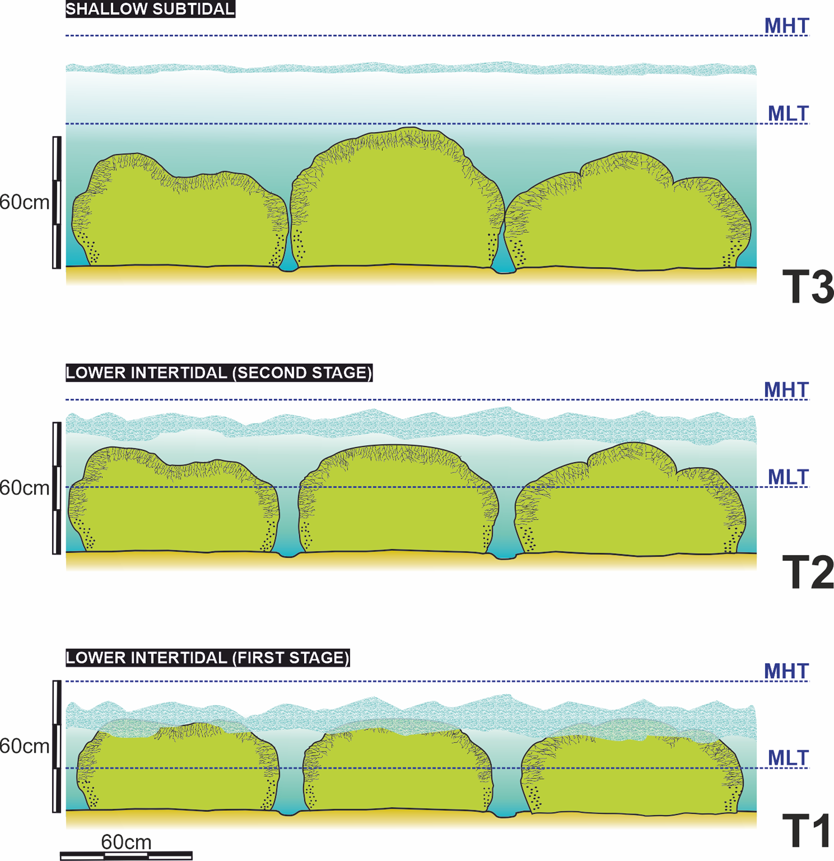
Fig. 11. Palaeoenvironmental evolution model of the stromatolites system. Depth conditions changed from lower intertidal (T1) to shallow subtidal (T3). T – time; MHT – mean high tide; MLT – mean low tide.

Fig. 12. 3D outcrop computer model representing the lower intertidal stage (T2 in Fig. 10). (a) Plan view during mean low tide (MLT). Note water run-off (arrows) along first- and second-order channels. (b) Side view during mean low tide. (c) Plan view during mean high tide (MHT). (d) Side view during mean high tide.

Fig. 13. Palaeoenvironmental reconstruction. Sunrise at Maimará lagoon. Note shorebirds at the left side. Artwork by Ignacio Díaz-Martínez and Carlos Cónsole-Gonella.
As it is interpreted in modern analogues (Logan et al. Reference Logan, Rezak and Ginsburg1964; Andres & Reid, Reference Andres and Reid2006; Dupraz et al. Reference Dupraz, Pattisina and Verrecchia2006), transition from a SH structure to a LLH-C in the internal variation of the more developed domes (Fig. 8c, d) indicates a decrease in hydrodynamic energy, probably as a result of an increase in water depth. The environment changed from lower intertidal to shallow subtidal (Fig. 11). This interpretation is indirectly sustained by the increased branching of the columns before the change to a LLH structure and the lack of desiccation cracks in the LLH structure (Kah et al. Reference Kah, Bartley, Frank and Lyons2006; Planavsky & Grey, Reference Planavsky and Grey2008; Mackey et al. Reference Mackey, Summer, Hawes, Jungblut and Andersen2015). As the depth increased, the waves lost prominence and sediment transport decreased (Bergman et al. Reference Bergman, Westphal, Janson, Poiriez, Eberli, Westphal, Riegl and Eberti2010).
It is possible that tide predominated over waves during this stage, and was responsible for continuing to fill the third-order channels. However, it is difficult to determine their participation in the architecture of this outcrop because we cannot rule out a biological stabilization of the domes and clusters previously formed under intertidal conditions (van de Vijsel et al. Reference van de Vijsel, van Belzen, Bouma, van der Wal, Cusseddu, Purkis, Rietkerk and van de Koppel2020). This increase in water level must have taken place under stable conditions, without changes in the balance between physical, chemical and biological factors, because there are no signs of interruptions along dome growth.
6. Conclusions
A sedimentological and facies multi-scale analysis of three-dimensionally preserved stromatolites allowed us to understand variations in hydrodynamics and overall palaeoenvironment of the Yacoraite Formation at Maimará locality, highlighting a direct relationship with the morphostructural development of stromatolites. These stromatolites were developed in a palaeoenvironment that varied from lower intertidal (c. 40 cm deep) to shallow subtidal (> 70 cm deep), close to the coastline, partially restricted and affected by hydrodynamic action.
The architecture of the deposit was directly affected by the hydrodynamic energy of the palaeoenvironment. Clusters are limited by first-order channels, usually developed perpendicular to the coastline with a clear hydraulic tendency, suggesting the transport of tidal water and/or stream water through them. On the other hand, water dissipation after run-off limited the lateral development of stromatolites with the formation of second-order channels inside clusters. Hydrodynamic energy also influenced the internal structure of the stromatolites. The structure of the SH type is explained as a product of hydrodynamic energy, where the third-order channels can be the result of differential erosive effects during run-off of water truncating the microbial mats in vivo. The increase in branching of the columns, and the subsequent transition from a SH structure to a LLH-C structure in the upper part of the domes of greater height, suggest an increase in water depth and a decay in the hydrodynamic energy of the palaeoenvironment where the waves lost prominence.
This new approach can also be applied in other subjects such as geochemistry and/or isotopic studies. Although our interpretation focuses on a specific area of the basin, it may be useful to evaluate similar records along the Late Cretaceous Central Andean basin.
Acknowledgements
This research was supported by grant PICT 2017-2057 (C. Cónsole-Gonella and S. de Valais) from the Agencia Nacional de Promoción Científica y Técnica (Argentina). We are grateful to the Maimará community and to colleagues R. Marquillas (Universidad de Salta and CONICET), M.C. Sánchez (Universidad Nacional de Salta), M. Griffin (Universidad Nacional de La Plata and CONICET) and P. Herrera-Oviedo (Universidad Nacional de Jujuy and CONICET) for their help in different stages of the fieldwork. We also thank Dr. Bas Van de Schootbrugge and two anonymous reviewers for their valuable comments on the manuscript.
Conflict of interest
None.
Supplementary material
To view supplementary material for this article, please visit https://doi.org/10.1017/S0016756821000315


