1. Introduction
Pressure solution is a deformation process by which grains dissolve at intergranular or intercrystalline contacts under high stress in an aqueous solution (Thomson, Reference Thomson and Ireland1959; Weyl, Reference Weyl1959; Rutter & Elliott, Reference Rutter and Elliott1976; Fletcher & Pollard, Reference Fletcher and Pollard1981; Rutter, Reference Rutter1983; Tada & Siever, Reference Tada and Siever1989). Such a process is caused by a higher solubility under non-hydrostatic stresses at grain-to-grain contacts. Two common types of pressure solution have been recognized: intergranular pressure solution and stylolitization (Houseknecht, Reference Houseknecht1984; Tada & Siever, Reference Tada and Siever1989; Dewers & Ortoleva, Reference Dewers and Ortoleva1990; Bjorkum, Reference Bjorkum1996). Intergranular pressure solution, as a diagenetic mechanism, contributes significantly to porosity reduction and compaction, serving as the agent of intergranular compaction and a source of cement (e.g. Sibley & Blatt, Reference Sibley and Blatt1976; Houseknecht, Reference Houseknecht1984, Reference Houseknecht1988; Tada, Maliva & Siever, Reference Tada, Maliva and Siever1987; Lehner, Reference Lehner1995; Renard, Ortoleva & Gratier, Reference Renard, Ortoleva and Gratier1997; Renard, Gratier & Jamtveit, Reference Renard, Gratier and Jamtveit2000; Yasuhara, Elsworth & Polak, Reference Yasuhara, Elsworth and Polak2003). Stylolites can be recognized by serrated surfaces within the rock mass, where insoluble minerals, such as clay, iron minerals and organic matter, are concentrated (Park & Schot, Reference Park and Schot1968). Based on their morphology, stylolites can be subdivided into several types with varied amplitudes of offset, column frequency, peak angles, orientations and connectivities (Fig. 1) (Koehn et al. Reference Koehn, Rood, Beaudoin, Chung, Bons and Gomez-Rivas2016). Stylolites have been regarded as an important cement source, especially for late diagenetic calcite spar (Oldershaw & Scoffin, Reference Oldershaw and Scoffin1967; Finkel & Wilkinson, Reference Finkel and Wilkinson1990; Rezaee & Tingate, Reference Rezaee and Tingate1997; Worden, Oxtoby & Smalley, Reference Worden, Oxtoby and Smalley1998; Baron & Parnell, Reference Baron and Parnell2007; Koehn et al. Reference Koehn, Rood, Beaudoin, Chung, Bons and Gomez-Rivas2016). Stylolites can prevent fluid flow (Heap et al. Reference Heap, Baud, Reuschle and Meredith2014), or serve as conduits for fluid flow (Carozzi & Von Bergen, Reference Carozzi and Von Bergen1987; Braithwaite, Reference Braithwaite1989).
Figure 1. Classification of stylolites: 1, smooth trace; 2, wavy columns; 3, sharp peaks; 4, rectangular columns; 5, composite texture; 6, fitted fabric. Modified from Park & Schot (Reference Park and Schot1968), Buxton & Sibley (Reference Buxton and Sibley1981) and Guzzetta (Reference Guzzetta1984).
It has been recognized that bedding-parallel fibrous veins (or ‘beef’) are common in black shales in sedimentary basins worldwide, where they are often taken as evidence for high pore fluid pressures (Cobbold et al. Reference Cobbold, Zanella, Rodrigues and Loseth2013). The characteristic feature of such veins is that they consist of parallel-aligned crystals with a maximum length of several centimetres, and exhibit a fibrous texture (Bons, Reference Bons2000; Bons, Elburg & Gomez-Rivas, Reference Bons, Elburg and Gomez-Rivas2012). Multiple mechanisms have been proposed to explain the genesis of these veins (Table 1); however, the debate still remains. The key questions to discuss mainly include: (1) the mechanism that triggered the initiation of bedding-parallel veins; and (2) the origin of the fibrous habit of crystals and the driving force for vein expansion.
Table 1. Summary of the proposed formation mechanisms of bedding-parallel mineral veins.

In this paper we report a field, isotopic, petrographic and crystallographic study of the bedding-parallel calcite veins in the Stair Hole Member exposed in Dorset, southern UK. The work extends the original study of El-Shahat & West (Reference El-Shahat and West1983) on the diagenesis of the Purbeck Formation by extending the investigation of the calcite veins to encompass their stratigraphic distribution, morphology, size, stable isotope geochemistry, petrography and c-axis crystallography. This paper aims to provide new evidence for: (1) the diagenetic environment for fibrous calcite veins; (2) the vein formation mechanism; and (3) the mutual interplay between vein fabrics and their growth processes. The results presented in this study suggest that there is a positive feedback between pressure solution and the development of bedding-parallel calcite veins during chemical compaction of the host fossiliferous sediments, when the thermal maturity of organic matter is not high enough to generate hydrocarbons. This study also raises the important possibility that the classical views regarding the formation mechanism of bedding-parallel veins in shale may need to be re-evaluated.
2. Geological background
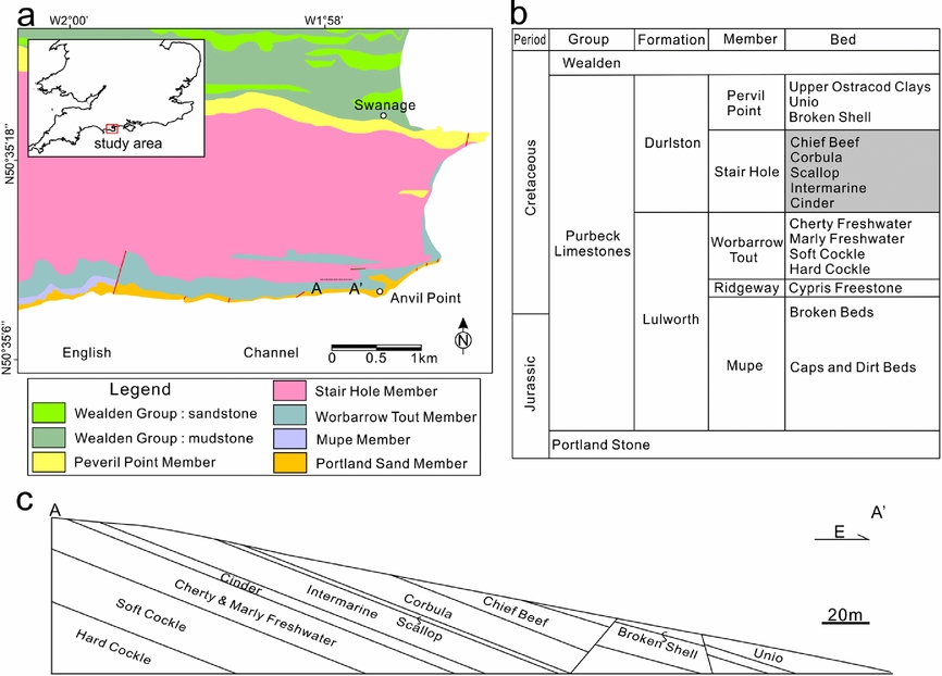
The study area is located on the coastal area of the Durlstone Bay, Dorset, southern UK (Fig. 2a). The cliffs expose 119 m thick alternating limestones and shales of the Purbeck Group (Upper Jurassic – Lower Cretaceous) (Fig. 2b, c). The beds are NWW–SEE-striking and gently dipping towards north at 10°. The lower boundary of the Purbeck is defined by the first occurrence of finely laminated, ostracod-rich limestones above the more massive, shelly limestones of the Portland Group (Horton, Reference Horton1995). The overlying Wealden Group can be identified by the occurrence of sandy mudstones above the last occurrence of limestones of the Purbeck Group (Stewart et al. Reference Stewart, Ruffell, Wach and Goldring1991; Robinson & Hesselbo, Reference Robinson and Hesselbo2004). The thin-bedded limestones and calcareous shales of the Purbeck Group have been considered as lagoonal deposits, which are richly fossilifeous, especially bivalves (Andrews & Walton, Reference Andrews and Walton1990; Stewart et al. Reference Stewart, Ruffell, Wach and Goldring1991; Radley, Barker & Munt, Reference Radley, Barker and Munt1998). There have been multiple rapid salinity fluctuations of the Purbeck Group. This is represented by a progressive change from evaporites of hypersaline origin in lower Purbeck strata to alternating freshwater, brackish and marine in the middle Purbeck strata to dominantly freshwater with influx of land-derived clastics in the upper Purbeck strata (Stewart et al. Reference Stewart, Ruffell, Wach and Goldring1991; Schnyder et al. Reference Schnyder, Ruffel, Deconinck and Baudin2006; Radley, Reference Radley2009). The middle part of the Purbeck Group has been extensively studied because the unlithified shell limestones are best developed within this interval (El-Shahat & West, Reference El-Shahat and West1983; Clements, Reference Clements1993; Westhead & Mather, Reference Westhead and Mather1996). The most common bivalve deposits of the Purbeck Group consist of disarticulated valves of brackish-water bivalves. The unlithified shell beds typically contain white aragonite shells, whereas the lithified shell beds are composed of biosparites or biosparrudites with varying content of aragonite retained (El-Shahat & West, Reference El-Shahat and West1983). Bedding-parallel calcite veins are commonly present in the Stair Hole Formation of the middle part of the Purbeck Group (El-Shahat & West, Reference El-Shahat and West1983; Westhead & Mather, Reference Westhead and Mather1996). The Stair Hole Formation can be further subdivided into five beds with different lithologies and degrees of lithification (Fig. 2b) (Westhead & Mather, Reference Westhead and Mather1996).

Figure 2. (a) Geological map of the study area in southern Dorset, UK. Modified from British Geological Survey (2000). (b) Simplified stratigraphic column of the Purbeck Group of the Wessex Basin. Modified from Hopson, Wilkinson & Woods (Reference Hopson, Wilkinson and Woods2008). (c) Cross-section of the cliffs exposed on the Durlston Bay along line A–A′ (see location in Fig. 2a).
3. Methods
An integrated research method of field, optical and SEM petrography and crystallography, as well as stable isotope geochemistry, was used to study the bedding-parallel veins. Field investigation mainly focused on the distribution, geometry and abundance of calcite veins and their host rock lithologies. Calcite veins and their host rocks were sampled for carbon and oxygen isotope measurements, to derive information on the carbonate source, diagenetic fluid and environment. The measurements were conducted using Thermo MAT 253 mass spectrometers at the Stable Isotope Geochemistry Laboratory of the Open University, following the procedure described by Meng, Hooker & Cartwright (Reference Meng, Hooker and Cartwright2017a). Oxygen (δ18O) and carbon (δ13C) isotopes were obtained at precision better than ±0.06 and ±0.05, respectively. Thin-sections of representative rock samples of calcite veins and surrounding rocks were cut perpendicular to bedding. We used a polarized light microscope and a FEI Quanta 650 scanning electron microscope (SEM) to observe vein microstructures, mineral compositions and diagenetic alternations of the host rocks. We also used the electron backscatter diffraction (EBSD) technique to quantitatively measure crystallographic preferred orientations (CPO) (Humphreys, Reference Humphreys2004) and sizes of calcite crystals in the vein samples, so that the information of crystal growth and palaeostress states could be revealed (Meng, Hooker & Cartwright, Reference Meng, Hooker and Cartwright2018). The polished thin-sections were mounted on a tilted SEM stage at 70° from the horizontal, with the vein walls being parallel to the x-axis of the stage. The measurement was conducted at 20 kV accelerating voltage, and a working distance of 10 mm from the EBSD detector. Electron beam scattering patterns were automatically collected using the Aztec software package for identification of the crystal orientations. The microstructural maps were then generated to spatially describe the crystal lattice orientations. The c-axis orientations of some selected crystals were plotted as lower-hemisphere, equal-area stereographic projections using the HKL Channel 5 software, which allows a comparison between these crystals.
4. Field observations
4.a. Vein distribution
Bedding-parallel, fibrous calcite veins were found in all the shale-containing beds of the Stair Hole Formation, except the Scallop Bed (Table 2). Fibrous calcite veins are prevalent in the Chief Beef Beds, occurring in every shale bed. They are most abundant in Bed 219 (Fig. 3a–e), which consists of bituminous shales of thickness 55 cm. The shales are rich in iron and original skeletal aragonite. The bedding-parallel veins are intensively developed and tightly clustered. Fifty-five veins occur along a linear scanline normal to bedding, with an average spacing of 6.35 mm (spacing is here defined as the thickness of shale between two neighbouring veins) (Fig. 4). Vein sizes vary over the range 0.2–2.8 cm in thickness, and 1–2 cm to tens of metres in length. Other shale beds of the Chief Beef Bed contain only one or two calcite veins (Fig. 3f–i). The veins lie either in the central part of the beds, or more commonly close to the neighbouring limestone beds (<10 cm). For example, two veins in Beds 205 and 207 were found to bound their host shales and a limestone bed (Bed 206) (Fig. 3g).
Table 2. Characteristics of the beds of the Stair Hole Formation exposed in the study area.

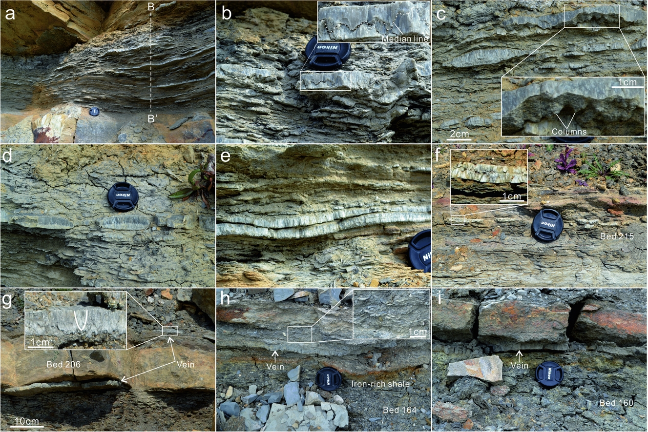
Figure 3. Field photographs showing the distribution of bedding-parallel calcite veins in beds (a–e) 219, (f) 215 and (g) 207 of the Chief Beef Bed; and (h) 164 and (i) 160 of the Corbula Bed. (a) Tightly spaced subhorizontal veins. (b) A 1.7 cm thick vein with a curvy median zone filled with dark host-rock inclusions. (c) Two neighbouring thick veins: the upper vein exposes the stylolite surface of its upper part and the enlarged area shows the forest of multiple columns; the lower vein exhibits a lenticular geometry with tapering tips. (d) Multiple veins exhibit rounded ends, with a geometry resembling boudinage structures. (e) Two neighbouring veins with a vertical spacing of only several millimetres. (f) A vein exhibiting a central medina zone and two fibrous parts. (g) Calcite veins above and beneath Bed 206. The enlarged area shows the upwards syntaxial growth of calcite fibres in the vein, indicated by the gradual coarsening of crystal aggregates. (h) A vein in iron- and shell-rich shales. The enlarged area shows the prevalent aragonitic shells above the vein. (i) A vein in iron-rich shales beneath the lower plane of Bed 165. Camera cap is 5.2 cm in diameter.

Figure 4. Vein thickness distribution along line B–B′. See location in Figure 3a.
Persistent bedding-parallel calcite veins with a maximum thickness of 1.3 cm were observed in Beds 160 and 164 of the Corbula Bed (Fig. 3h, i). This bed also contains abundant aragonitic bivalves and gastropods, which have not been lithified. The only shale bed of the Intermarine Bed, Bed 130 consists of a 1.5 cm thick calcite vein and prevalent shell debris. Three to four closely spaced calcite veins were found at the more argillaceous, uppermost part of the Cinder Bed (Bed 111), which contains bluish, grey shelly limestone with oysters. The veins are persistent in length and vary over the range 2–5 mm in thickness.
4.b. Morphology
The calcite veins are either tabular-shaped and persistent in length, or are spindle-shaped with conspicuous tips (Fig. 3c). Some vein tips sharply taper, whereas many others exhibit blunt or even rounded tips (Fig. 3d). The veins consist of closely packed vertical fibres, which are approximately normal to vein-walls. Some calcite veins contain a median zone that bounds the upper and lower fibres (Fig. 3f). The median zones are either straight or curvy, and are mostly nearer to the lower vein-walls, that is, the upper fibres are predominantly longer than the lower fibres. The curvy median zones exhibit characteristic features of stylolites (Fig. 3c), with a maximum column amplitude of 8 mm. The crowns of individual columns are commonly curvy, and the peaks are rather blunt. Three-dimensional shapes of stylolites are occasionally weathered out, exposing a forest of columns and matching pits normal to the planes of the stylolites. Median zones are commonly absent from many calcite veins (Fig. 3g). In such veins, calcite fibres become coarser towards the upper vein-walls, exhibiting a syntaxial, upwards growth.
Vein surfaces are commonly irregular. The rugosity of vein planes can be attributed to the variable degrees of fibre protrusions into the host rocks. For example, the uppermost calcite vein of Bed 219 (Chief Beef) with rough planes results in the corresponding irregularity in the contact with the limestone of Bed 220 (Broken Shell) (Fig. 5a). This demonstrates that the longer fibres in the vein have protruded into the limestone, causing a differential compaction of the limestone. It is also observed that thin calcite veins at the top of the Cinder Bed contain numerous bivalve residues on vein surfaces (Fig. 5b). The fossil morphologies are rather intact, which contributes to the irregular surface geometry of vein planes.
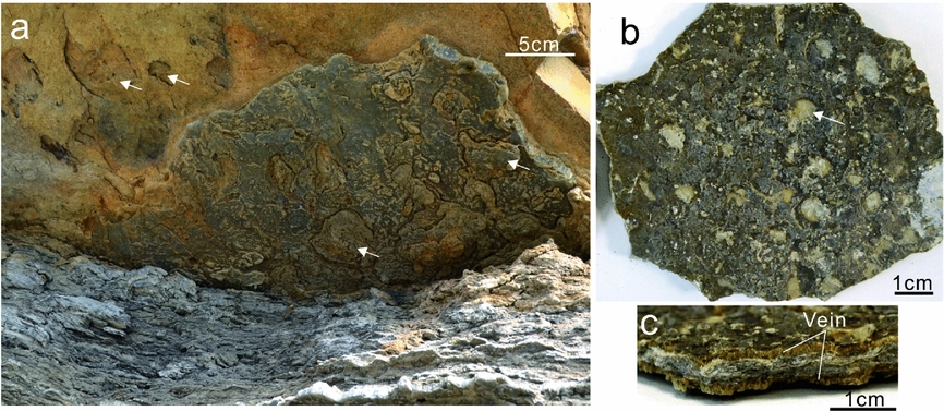
Figure 5. Surface morphology of calcite veins from beds (a) 219 and (b, c) 111. (a) The non-smooth lower surface of the calcite vein beneath the limestones of Bed 220. The arrows point to the circular depressions in the lower plane of the limestone bed, which could correspond to the circular protrusions in vein planes. (b) The upper surface of a thin vein. The arrow points to a typical circular depression which resulted from shell remains. (c) Cross-section view of the sample in (b). The two thin veins are bounded by biosparrudite limestone.
5. Stable isotope signatures
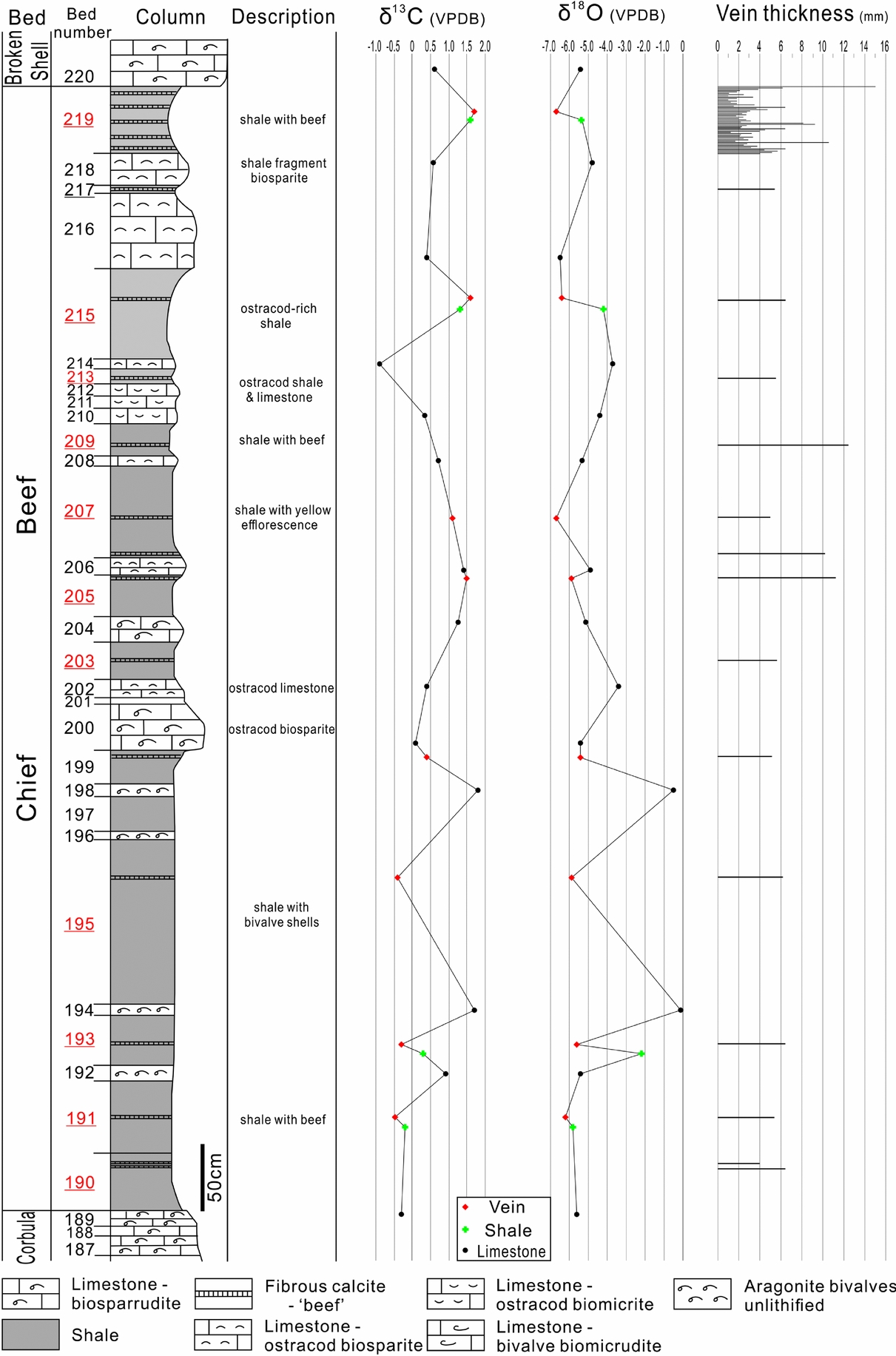
The δ13C values of the calcite veins from the Chief Beef Bed vary from –0.49 to 1.78‰ PDB (Fig. 6). Coupled with their δ18O compositions, the veins can be subdivided into two groups (Fig. 7). Veins of group I mostly occur in the upper part of this bed and exhibit positive δ13C values ranging from 1.11 to 1.78‰ PDB. Group II are located in the lower part of this bed and have negative values ranging from –0.49 to –0.30‰ PDB. The δ18O values of both groups are between –6.74 and –5.47‰ PDB, and are generally overlapped and undifferentiable.

Figure 6. Stratigraphic column of the Chief Beef Bed with lithological descriptions, carbon and oxygen isotope compositions of veins, shales and limestones, and also vein thickness. The beds containing calcite veins are highlighted by underlining bed numbers. The column is modified from El-Shahat & West (Reference El-Shahat and West1983).

Figure 7. Plot of carbon versus oxygen isotope values of calcite veins, shales and limestones from the Stair Hole Member.
The limestones of the Chief Beef Bed exhibit varied stable isotope compositions, –0.90 to 1.85‰ PDB of δ13C values, and –6.53 to –0.03‰ PDB of δ18O values (Fig. 6). The δ13C compositions of the limestones are similar to those of calcite veins; however, their δ18O compositions cross a much wider range. The anomalies of δ18O values occur in Beds 192, 194 and 198, which all consist of unlithified aragonitic bivalves, with δ18O values ranging from –0.54 to –0.03‰ PDB. The limestone beds with δ18O values from –4.00 to –3.00‰ PDB consist of ostracod biosparite limestone. The biosparrudite limestone beds fall into a narrow range of δ18O values from –5.15 to –5.37‰ PDB. The δ18O values of other types of limestones are overlapped between –6.53 and –4.43‰ PDB.
The shale beds of the Chief Beef Bed exhibit a narrower range of stable isotope compositions than the limestone beds, with δ13C values between –0.18 and 1.61‰ PDB, and δ18O values between –5.86 and –2.18‰ PDB. An anomaly appears in Bed 193, which is adjacent to two unlithified bivalve beds and exhibits a less negative δ18O of –2.18‰ PDB.
The other calcite vein samples from the Corbula, Intermarine and Cinder Beds all have positive δ13C values ranging from 0 to 1‰ PDB, and δ18O values ranging from –6 to –5‰ PDB. It is notable that the calcite veins from the Cinder Bed exhibit higher δ13C and lower δ18O values than those of their host rocks (Fig. 8).
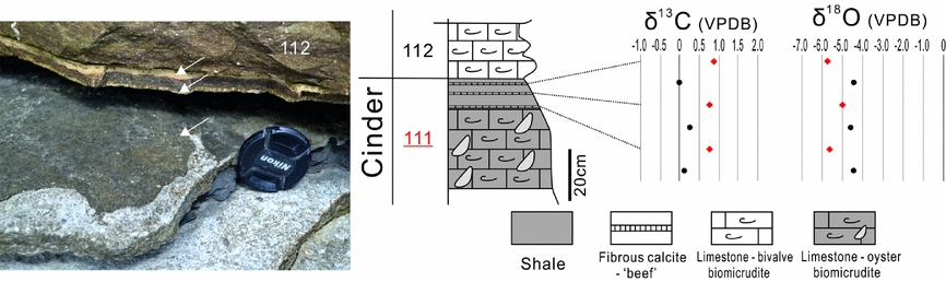
Figure 8. The calcite veins lying on the topmost part of Bed 111 of the Cinder Bed, and the carbon and oxygen isotope compositions of the veins and their host rocks.
6. Petrography
6.a. Microtextures
The curvy median zones of stylolites in individual calcite veins consists of multiple columns with a height ranging from 0.2 to 2.1 mm, and a frequency of 0.7 mm–1 (Fig. 9). The stylolites mainly contain insoluble clay minerals, organic matter and pyrite microcrystals. The thickness of the stylolites varies from several microns to 0.6 mm. The original structure of fine laminations has largely been retained (Fig. 9b, c), which are parallel to the contacting flanks of columns. Plastic deformation and shear fractures commonly occur in the clay aggregates.
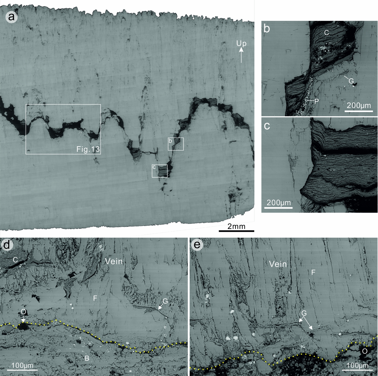
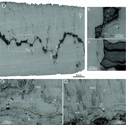
Figure 9. SEM backscattered electron images showing representative microstructures of fibrous calcite veins. (a) A bedding-parallel calcite vein consisting of a wavy median zone with insoluble residues of shale fragments, pyrite microcrystals and organic matter. The enlarged areas show (b) shale fragments along the steep flank of a column and (c) in a trough of a column. Note that the shale laminations are generally horizontal; however, the segments contacting uneven crystal faces are folded and parallel to the crystal faces. (d, e) Ghosts of bivalve fragments within bedding-parallel calcite veins. Note that the bivalve fragments are mostly subhorizontal and normal to calcite fibres, whereas some fragments are gently or steeply inclined. B – bivalve; C – clay; F – fibre; G – ghost of bivalve fragments; O – organic matter; P – pyrite.
Calcite occurs in two major forms in the veins, either as equant, small crystals, or as larger fibres with a much higher aspect (length/width) ratio. Here, small crystals are defined as those with an area size less than 104 μm2. The small calcite crystals are predominantly concentrated along the stylolites, especially at the crowns of individual columns. These crystals have an average area size of 2368 μm2, and an average aspect ratio of 3.3. The larger calcite crystals have an average area size of 29443 μm2 and an average aspect ratio of 7.0, indicating that larger crystals tend to exhibit a lenticular or fibrous morphology. The calcite fibres are parallel, tightly aligned with the long axes lying vertically. The lower parts of single veins are generally pure in composition, whereas the upper parts contain numerous scattered inclusion patches of clay grains, pyrite and also organic matter. The upper walls of the veins also often exhibit a greater irregularity than the lower walls (Fig. 9a).
Ghosts of bivalve fragments are commonly observed to be embedded within the fibrous veins (Fig. 9d, e). The bivalve fragments are commonly flat or curved. Their length ranges from 20 to 150 μm, and thickness from 1 to 4 μm. The bivalve fragments mostly lie parallel to bedding; however, some fragments are oblique to bedding at an angle of up to 55°. Clay aggregates are commonly associated with the bivalve fragments. The clay aggregates, with a thickness of 5–80 μm, predominantly lie below the bivalve fragments. Fibrous calcite crystals, which lie above the bivalve fragments, are rooted in the fragments, with little host-rock inclusions between them.
A crystalline mosaic of small, equant calcite crystals were also found filling the moulds of skeletal fragments as a sparry calcite cement (Fig. 10). The crystal morphologies are similar to those in the stylolites of fibrous veins. Individual crystals are discernible with the long dimension ranging over 5–300 μm. The morphologies of the skeletal fragments are well preserved, possibly because the cementation process pre-dates mechanical compaction, so that crushing of the shell fragments has been avoided. Such sparry calcite cements have been suggested to be the result of neomorphism of aragonite during diagenesis, and represent an important manifestation of porosity reduction (El-Shahat & West, Reference El-Shahat and West1983).

Figure 10. (a) Photomicrograph showing the cement of sparry calcite filling shell remains. Cross-polarized light. (b) Inverse pole figures (along y direction) showing crystallographic orientations of sparry calcite in a fossil mould.
6.b. Microstylolites
Microstylolites are commonly observed in the calcite veins, and truncate calcite crystals (Fig. 11). These microstylolites can be identified by wavy seams of organic matter with a maximum thickness of 22 μm (Fig. 11a, b). The microstylolites are generally subhorizontal; however, most veins contain inclined or even vertical segments. Some microstylolites occur as interconnecting networks, consisting of multiple stylolites in varying orientations that do not cross-cut each other (Fig. 11c, d). These microstylolite networks mainly appear in closely packed aggregates of relatively small crystals with insoluble inclusions along crystal boundaries, exhibiting a fitted fabric. Unlike macrostylolites, single microstylolites either have sharp peaks or are composites of wavy or rectangular fragments with minor jagged surfaces. The amplitude of single columns ranges over 1–115 μm.

Figure 11. Pressure-solution features within fibrous calcite veins. (a) A microstylolite defined by a thin seam of organic matter with a maximum thickness of 17.5 μm. (b) A thin microstylolite exhibiting a composite fabric. (c) Interconnecting microstylolites exhibiting a fitted fabric. (d) Line-drawing traces of stylolites shown in (c). (e, f) Varied grain-contact styles in bedding-parallel calcite veins. Note that the larger fibres exhibit smooth crystal boundaries and lack evidence for pressure solution. a – indenting contact; b – truncating contact; c – interpenetrating contact.
6.c. Grain contacts
The small, equant calcite grains within the calcite veins have different shapes and radii. Neighbouring grains in contact exhibit grain surface solution textures (Fig. 11e, f). The grains with the smaller radius of curvature commonly penetrate into the grain with the larger radius of curvature, resulting in an indenting grain contact as the most common type of grain contacts. Neighbouring grains with similar radii often exhibit flat contacts, which are identified as truncating grain contacts. Interpenetrating grain contacts, that is, mutually interlocking protrusions of grains into each other, were also observed. The sutured grain boundaries exhibit a similar morphology to microstylolites. In contrast to the equant grains, the vertical calcite fibres predominantly have smooth fibre boundaries, lacking signs of solution textures on grain surfaces (Fig. 11f).
6.d. Deformation twins
Intracrystalline deformation by twinning was observed to be concentrated along the stylolites in the calcite veins (Fig. 12). The deformation twins gradually disappear towards vein walls. This suggests that the twins formed during the early stage of fibre growth as growth twins, rather than deformation twins formed due to the loading of tectonic stress. Otherwise, the distribution of twins would be expected to be more homogeneously distributed within the veins. The twin sets often exhibit an interfingering pattern. Because the maximum principal stress σ 1 is ideally at about 45° to the glide plane (Lacombe, Reference Lacombe2010; Fossen, Reference Fossen2016), the interfingering twins suggest a subvertical σ 1 that was responsible for creating those twins.
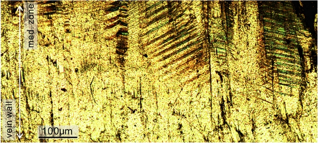
Figure 12. Photomicrograph showing the localized distribution of deformation twins in bedding-parallel calcite veins. Note that twins are absent from the outer part of the vein. Cross-polarized light.
7. C-axis fabrics
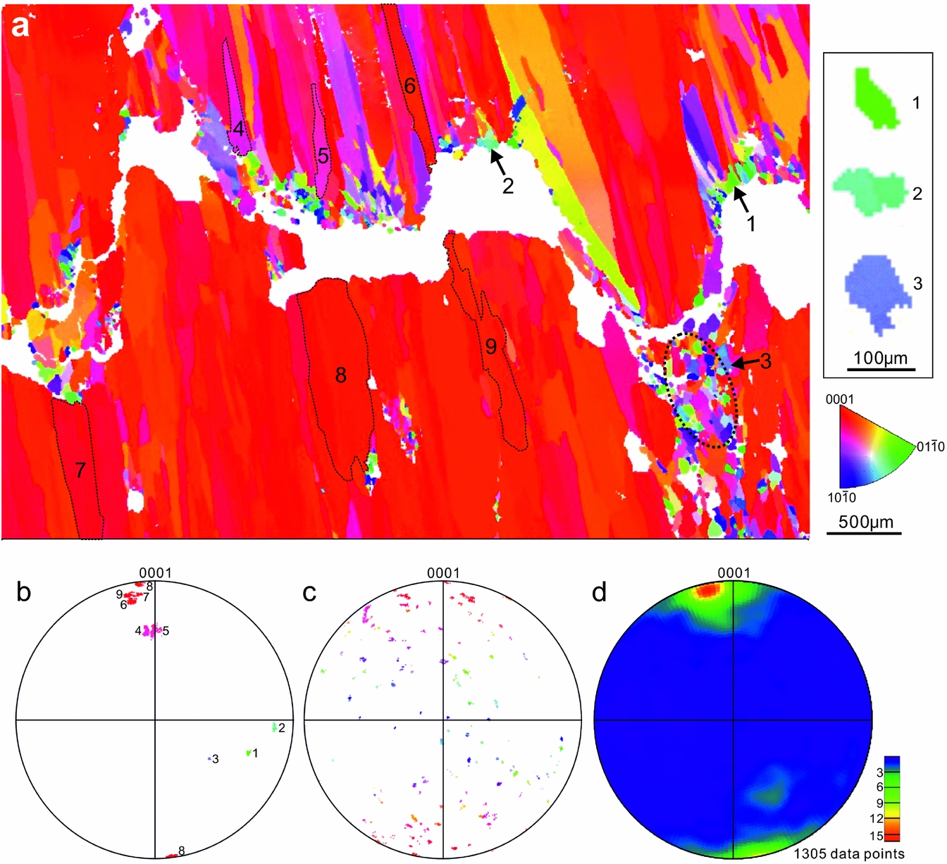
EBSD results demonstrate that the equant calcite crystals along the stylolites predominantly exhibit random c-axis orientations (Fig. 13a–c), whereas the much larger fibres exhibit a preferred c-axis orientation in the subvertical direction (Fig. 13a, b, d). Some fibres with a medium plunge (e.g. fibres 4 and 5 in Fig. 13a) are commonly overgrown by neighbouring fibres. Those fibres have a tapering tip pointing towards vein walls. The steeply plunging calcite fibres tend to have a constant crystal width during growth, which is greater than low–medium plunging calcite fibres or equant grains. In contrast to the fibres, the sparry calcite cement filling skeletal fragments exhibit random c-axis orientations, and similar crystal sizes to those in vein stylolites (Fig. 10b).

Figure 13. (a) Inverse pole figure (along y direction) showing the crystallographic preferred orientations (CPO) of a representative calcite vein (y direction is vertical). See sample location in Figure 9a. (b) Stereonet projections of c-axis pole orientations of the selected calcite crystals in the vein presented in (a). Lower hemisphere. The number of data points for grains 1–9 are 78, 110, 181, 1366, 1329, 2786, 4237, 10770 and 4589, respectively. (c) C-axes poles of the equant calcite crystals in the circular area of (a). 5283 data points. (d) Contoured plot of c-axis pole orientations of 1305 calcite crystals larger than 104 µm² in area. One data point per crystal.
8. Discussion
8.a. Diagenetic environment
Previous studies have demonstrated that local dissolution of bioclasts (δ13C ≈ 0‰) could provide carbonate for the precipitation of calcite in veins (Marshall, Reference Marshall1982; Wolff, Rukin & Marshall, Reference Wolff, Rukin and Marshall1992; Meng, Hooker & Cartwright, Reference Meng, Hooker and Cartwright2017a). The carbon isotope values of bedding-parallel calcite veins (–0.5 to 1.8‰) presented in this study fall within a similar range to those of their host rocks (Figs 6–8). The approximately equal values of δ13C of calcite veins, shales and limestones could then suggest that the veins largely derived their carbonates from the host sediments. The source of the calcite could be neomorphic calcite provided by aragonitic fossils or sparry calcite cements filling pore spaces, or a combination of both. The prevalent aragonitic shells in the limestone and shale beds of the Stair Hole Formation, especially those embedded on vein surfaces and also within the veins (Figs 5b, c, 9d, e), could have released abundant carbonate for the growth of adjacent veins. This is because aragonite, as a more soluble polymorph of calcium carbonate, is metastable and readily transforms to calcite during burial (Maliva & Dickson, Reference Maliva and Dickson1992; Hendry, Ditchfield & Marshall, Reference Hendry, Ditchfield and Marshall1995). In particular, the calcite veins and their host shales in beds 191, 193, 205, 215 and 219 share similar ranges of δ13C values, suggesting that the veins were self-sourced by their host shales. It is notable that the unlithified aragonitic shell beds exhibit relatively more positive carbon isotope compositions, for example beds 194, 198 and 206 (Fig. 6). This could help to explain the higher δ13C values of calcite veins in shale beds 205, 215 and 219, because the carbonate mineralogy in these beds predominantly consists of unlithified skeletal aragonite as the carbonate source for the calcite veins in the beds.
Organically derived bicarbonate with depleted 13C (δ13C ≈ –25‰ PDB) has been suggested as an alternative source for calcite veins, through in situ decomposition of organic matter under sulphate-reducing conditions (Hudson, Reference Hudson1978; McLane, Reference McLane1995). Although the dark shales in the Stair Hole Formation is organic rich, the carbon isotope compositions of the calcite veins are not compatible with those infilled with organically derived carbonate. Moreover, the calcite veins presented in this study are mainly composed of ferroan calcite (El-Shahat & West, Reference El-Shahat and West1983), similar to that of neighbouring compacted biosparrudite. Ferroan calcite could not have been readily precipitated while SO42− was present and transformed to S2− and H2S, indicating that the precipitation of ferrous calcite for the calcite veins and calcite cements of the compacted biosparrudite post-dated the process of bacterial sulphate reduction.
The oxygen isotope composition of carbonates is a function of the isotope composition and temperature T (°C) of the water in which the carbonate minerals were precipitated (Boggs, Reference Boggs2009). This relationship is determined by:
 $$\begin{equation}
T = 16.9 - 4.2\left( {{\delta _{\rm{c}}} - {\delta _{\rm{w}}}} \right) + 0.13{\left( {{\delta _{\rm{c}}} - {\delta _{\rm{w}}}} \right)^2}
\end{equation}$$
$$\begin{equation}
T = 16.9 - 4.2\left( {{\delta _{\rm{c}}} - {\delta _{\rm{w}}}} \right) + 0.13{\left( {{\delta _{\rm{c}}} - {\delta _{\rm{w}}}} \right)^2}
\end{equation}$$
where δ c is the equilibrium oxygen isotope composition of calcite and δ w is the oxygen composition of the water from which the calcite was precipitated. The oxygen isotope composition therefore becomes more negative as the burial depth and temperature increases. The δ18O values of the unlithified aragonitic shell beds 194 and 198 are c. 0‰ PDB (Fig. 6), suggesting that the seawater had an original oxygen isotope composition of approximately zero per mil. If we assume that the diagenetic fluids for the calcite veins only consist of original seawater, from Equation (1) the formation temperature of the calcite veins would be c. 52.3–53.2°C when given a δ18O value of –5 to –6‰ PDB. However, the calculated temperatures are too high to be compatible with the palaeotemperature indicators of apatite fission track and vitrinite reflectance data reported in previous studies (Fig. 14) (Bray, Duddy & Green, Reference Bray, Duddy, Green and Underhill1998; Greenhalgh, Reference Greenhalgh2016). This indicates that the diagenetic fluids from which calcite was precipitated could have more negative oxygen isotope compositions, and contain 18O-depleted water constituents. Such porewater constituents are mostly likely isotopically light meteoric waters: it has been suggested that the precipitation of ferroan calcite cement for the compacted biosparrudites, which exhibit similar oxygen isotope ranges to the calcite veins, occurred as a typical phreatic process (Richter & Fuchtbauer, Reference Richter and Fuchtbauer1978). The mixing of seawater and isotopically light meteoric waters would affect the overall δ18O signatures of the calcite precipitates. It should also be noted that evaporation may have occurred and caused a heavier isotope composition, although this effect is less likely to be a factor in a deep environment and also in a closed system.

Figure 14. Burial curve and thermal history of the Purbeck Group and the Lower Lias Group. Data derived from Kimmridge-5 well in Dorset. Modified from Greenhalgh (Reference Greenhalgh2016).
In summary, the bedding-parallel calcite veins were mainly sourced by the host shales during burial, and post-date bacterial sulphate reduction. Calcite was precipitated from pore waters, which were a mixing of the original seawater and 18O-depleted meteoric waters.
8.b. Vein generation and the palaeostress states
The stylolites (Figs 3b, c, 9a), microstylolites (Fig. 11a–d) and grain contact styles (Fig. 11e–f) found within the calcite veins suggest that pressure solution commenced during chemical compaction of their host sediments. The onset of chemical compaction has been suggested to occur at some point between 200 and 1500 m burial depth (Boggs, Reference Boggs2009; Goulty, Ramdham & Jones, Reference Goulty, Ramdham and Jones2012). Based on the burial history of the Durlstone Formation (Fig. 14), it is suggested that the calcite veins formed during burial and diagenesis, that is, chemical compaction, of the host sediments. Coupled with evidence from the predominant horizontal directions of stylolites and the interfingering twins in the calcite fibres (Fig. 12), it is inferred that the vertical compressional stress leading to pressure solution is the gravitational stress due to the overburden load.
The small, equant calcite crystals along the stylolites within calcite veins (Figs 11e, f, 13a) are similar to the sparry calcite filling shell moulds (Fig. 10), regarding crystal morphologies, sizes, crystallographic orientations and contact styles. Given the common coexistence of ghosts of bivalve fragments (Fig. 9d, e), those equant calcite in veins are interpreted to result from neomorphism of skeletal aragonite. The stylolites, as the vein initiation sites, could have formed due to pressure solution of neomorphic calcite within the horizons where aragonitic shells are concentrated when the neomorphic calcite grains became large enough to make contact with neighbouring grains. The stylolites generally lie in the horizontal direction with columns aligned vertically due to the lithostatic stress (overburden load).
The most commonly advocated mechanism to explain the genesis of fibrous calcite veins is that of overpressure triggered by primary oil migration from thermally matured organic matter (Stoneley, Reference Stoneley1983; Parnell & Carey, Reference Parnell and Carey1995; Parnell et al. Reference Parnell, Honghan, Middleton, Haggan and Carey2000; Cobbold & Rodrigues, Reference Cobbold and Rodrigues2007; Rodrigues et al. Reference Rodrigues, Cobbold, Loseth and Ruffet2009; Zanella et al. Reference Zanella, Cobbold and Boassen2015; Hooker et al. Reference Hooker, Cartwright, Stepehnson, Silver, Dickson and Hsieh2017). This is theoretically possible because: (1) fluid pressure can hold apart fracture walls, and create dilational sites for the precipitation of calcite crystals when fluid pressure exceeds the sum of the minimum principal stress and the tensile strength of the shales (Stoneley, Reference Stoneley1983); and (2) liquid oil has been observed within fluid inclusions in horizontal calcite veins (e.g. Parnell, Carey & Monson, Reference Parnell, Carey and Monson1996; Parnell et al. Reference Parnell, Honghan, Middleton, Haggan and Carey2000). However, this mechanism is considered unlikely for the fibrous veins of the Stair Hole Member for a number of reasons.
Firstly, it has been suggested that the black Cretaceous shales as well as the underlying Kimmeridge Clay Formation are too immature to generate oils (Fig. 14) (Scotchman, Reference Scotchman1987, Reference Scotchman1989; Underhill & Stoneley, Reference Underhill, Stoneley and Underhill1998). Oil inclusions were not found within the calcite veins, so there is no direct evidence that overpressure could have developed as a result of hydrocarbon generation. Secondly, overpressure could retard or completely shut down chemical compaction, because the elevated pore fluid pressures would reduce stresses at grain contacts and hence inhibit the production of stylolites (Scholle, Reference Scholle1977; Pittman & Larese, Reference Pittman and Larese1991; Paxton et al. Reference Paxton, Szabo, Ajdukiewicz and Klimentidis2002). Moreover, the extremely narrow spacing of the horizontal veins in Bed 219 of the Chief Beef Bed (Figs 3a, c, e, 4) may not favour a formation mechanism of hydraulic fracturing. According to fracture mechanics, the thickness of parallel horizontal hydrofractures is determined by (Mandl, Reference Mandl2005):
 $$\begin{equation}
\frac{{\delta d}}{d} = \frac{{1 - {v^2}}}{E}\left( {p - {\sigma _{\rm{v}}}} \right)
\end{equation}$$
$$\begin{equation}
\frac{{\delta d}}{d} = \frac{{1 - {v^2}}}{E}\left( {p - {\sigma _{\rm{v}}}} \right)
\end{equation}$$
where δd is fracture thickness; d is the distance between the mid-planes of neighbouring fractures; v is the Poisson's ratio; E is Young's modulus; p is pore fluid pressure; and σ v is overburden stress. The average fracture thickness of single fractures δd av from the fluid injection point to the fracture tip can be determined by:
 $$\begin{equation}
\delta {d_{{\rm{av}}}} = 3.14\frac{{1 - {v^2}}}{E}\left( {p - {\sigma _{\rm{v}}}} \right)L
\end{equation}$$
$$\begin{equation}
\delta {d_{{\rm{av}}}} = 3.14\frac{{1 - {v^2}}}{E}\left( {p - {\sigma _{\rm{v}}}} \right)L
\end{equation}$$
where L is the fracture length. Combing Equations (2) and (3), the approximation of the fracture spacing can be determined by:
 $$\begin{equation}
d \approx 3L.
\end{equation}$$
$$\begin{equation}
d \approx 3L.
\end{equation}$$
Such a relationship between vein spacing and length is apparently not compatible with the calcite veins present in this study. Nevertheless, the condition that d << 3L may still occur, but only if the veins formed by crack-seal processes (Ramsay, Reference Ramsay1980). However, the critical evidence for crack-seal events (i.e. inclusion trails and bands) was not observed in the veins. Furthermore, if we assume that all veins have an equal growth rate, and thicker veins formed earlier than thinner veins, the nucleation of new hydrofractures would preferentially occur along the interfaces between pre-existing calcite-filled veins and the host rocks because of the weak bonding between them (Bons & Montenari, Reference Bons and Montenari2005). It is therefore difficult to explain why new hydrofractures would have nucleated in horizons adjacent to the earlier veins rather than taking advantage of the weak planes of pre-existing vein-walls, especially in the case of neighbouring veins with a spacing of < 1 cm (Fig. 3e). However, in contrast, such a narrow spacing of veins can lend support to the role of pressure solution, because a decrease in bulk permeability induced by pressure solution favours a narrow spacing of parallel veins, as suggested in the cnoidal waves theory used for explaining the spacing of rhythmic bands in zebra dolomite (Kelka et al. Reference Kelka, Veveakis, Koehn and Beaudoin2017).
In summary, pressure solution during burial of the host sediments is suggested to have promoted the development of bedding-parallel calcite veins, which was facilitated by a vertical maximum compressive stress due to the overburden load.
8.c. Relationship between vein fabrics and vein growth process
In contrast to the calcite fibres, the calcite grains localized along the stylolites within calcite veins exhibit three main characteristic features revealed by our petrographic observations and EBSD measurements: (1) they have much smaller crystal sizes than the fibres; (2) they exhibit random c-axis orientations; and (3) pressure solution commonly occurs at interpenetrating or sutured grain contacts. These grains are similar to the sparry calcite filling fossil moulds (Fig. 10), and are regarded as early cement filling pore spaces in the shale matrix. Because stylolites have been suggested to be a major cement source in carbonate rocks (e.g. Hudson, Reference Hudson1975; Finkel & Wilkinson, Reference Finkel and Wilkinson1990; Heydari, Reference Heydari2000), the stylolites within the calcite veins could have provided carbonates for the growth of calcite fibres, given the fact that the vein fibres grew from the stylolites towards the host rock. After mechanical compaction had essentially been completed and a stable grain framework had been established, dissolution of calcite could have largely occurred at grain contacts of the small equant calcite grains, as revealed by the prevalent pressure-solution features. These grains are more readily dissolved during chemical compaction, possibly because: (1) a mixture of grain sizes will lead to preferential dissolution of finer grains (Weyl, Reference Weyl1959); or (2) preferential dissolution of calcite grains would occur where their c-axes were not perpendicular to bedding, as calcite is most stable in situ with c-axes parallel to the direction of the maximum principal stress (Kamb, Reference Kamb1959; O'Brien et al. Reference O'brien, Manghnani, Tribble, Wenk, Rezak and Lavoie1993), that is, vertical in the present study (Fig. 15). The dissolved carbonates would then have been transported through pore spaces to the sites for precipitation from pore waters.

Figure 15. Simplified sketch illustrating the three-dimensional geometry and texture of bedding-parallel fibrous calcite veins. Modified from Railsback (Reference Railsback2002). The enlarged area shows the pressure-solution sites where equant, sparry crystals are concentrated. Those sparry crystals may release calcite for increments of the outer fibres during pressure solution. F – fibre; I – insoluble minerals; P – protrusion.
Considering the low permeability of shales, it is more likely that solutes of calcite were transported by diffusion. The diffusive transfer could also be enhanced by the clay grains filling the stylolites and intergranular spaces because a clay film, consisting of multiple clay platelets with associated fluid films (Fig. 9b, c), could provide numerous diffusion paths (Renard et al. Reference Renard, Dysthe, Feder, Bjorlykke and Jamtveit2001).
The calcite fibres exhibit a continuity during growth and preferred subvertical c-axis orientations normal to bedding. This indicates that such c-axis orientations are more resistant to the overburden load. From the perspective of the thermodynamic theory of equilibrium under non-hydrostatic stress, the preferred c-axis orientation of calcite, as the weakest axis, tends to align with the maximum principal stress σ 1 (Kamb, Reference Kamb1959) when recrystallization occurs by solution and re-deposition, in order to minimize the chemical potential required for equilibrium across the plane normal to the σ 1 axis. Calcite fibres with subvertical c-axes can therefore grow preferentially, whereas the others would be overgrown by fibres.
The calcite fibres exhibit two types of growth: (1) displacive growth, that is, surrounding shales have been displaced by calcite veins to accommodate their expansion; and (2) volume-for-volume replacive growth, that is, calcite fibres protrude into the contacting limestone beds, causing dissolution of the host limestones and re-precipitation of calcite on vein surfaces with an equal volume (Fig. 5). Both processes have been suggested to be controlled by the force of crystallization (Weyl, Reference Weyl1959). Although vein-displacive growth would be expected to be accompanied with vertical displacement of the surrounding shales, the volume of the bulk rock did not necessarily increase (Selles-Martinez, Reference Selles-Martinez1996); instead, shale beds could have been shortened during fibre growth. This is because the dissolution of aragonite and sparry calcite and re-deposition of calcite could have maintained the solid volume balance while the pore volume was reduced during the process of chemical compaction. The volumetric expansion of bedding-parallel veins could therefore have been established by redistribution of carbonates in the hosts, and led to further bedding compaction.
Replacive growth of calcite fibres, which is represented by the irregular depressions on limestone planes and corresponding fibre protrusions, can only be observed at vein–limestone contacts (Fig. 5) because the authigenic calcite is incapable of mechanical displacement of the host limestones. The force of crystallization by growing calcite fibres exerted on the contacting limestones would result in an increase in the Gibbs free energy and hence a higher solubility of the hosts. This would produce a new dynamic equilibrium, in which authigenic calcite grew inwards into the host phase. In particular, the truncated ghosts of fossil fragments in biosparrudite, bounding calcite veins and limestones are typical representatives of vein-replacive features. Moreover, the similar values of carbon isotope compositions of neighbouring limestone beds and calcite veins (e.g. beds 205 and 206) could further suggest that the veins have derived their carbonates from the contact zone with the limestone beds by pressure solution arising from the force of crystallization controlled.
In summary, the petrographic and geochemical evidence presented overwhelmingly suggests that calcite fibres with subvertical c-axes grew preferentially due to the overburden load. The fibres exhibit a displacive growth in porous shales and a replacive growth at vein–limestone contacts, both phenomena ultimately controlled by the force of crystallization.
9. Conclusions
(1) The fibrous calcite veins in black shales (Cretaceous, southern UK), with δ13C compositions of around zero per mil, derived carbonates mainly from the host rock. Pore fluids, from which calcite was precipitated, were a mixture of the original seawater and 18O-depleted meteoric waters.
(2) Pressure solution, which is evident from stylolites, microstylolites and grain contact styles, occurred in the calcite veins. Pressure solution of sparry calcite as pore-filling cements is interpreted to have promoted the development of bedding-parallel calcite veins as a positive feedback mechanism during early burial of the sediments. Neomorphic calcite in the host shales and dissolved calcite from vein initiation localities could serve as carbonate sources for subsequent fibre growth.
(3) Calcite fibres exhibit a displacive growth in porous shales and a replacive growth at vein–limestone contacts, indicating the driving force of crystallization pressure of calcite.
(4) CPO patterns of calcite fibres could form as a response to the overburden pressure as the maximum principal stress during vein expansion.
(5) This study suggests that pressure solution could cause the formation of bedding-parallel calcite veins in black shales, especially those with a low organic maturity.
Acknowledgements
This research was funded by Shell International Exploration and Production B.V. We thank Jon Wells for sample preparation and Simona Nicoara for geochemical measurements. We also thank Ian West for providing online study materials. This paper benefited greatly from the constructive reviews of Olivier Lacombe, Paul Bons and Nicolas Beaudoin.