


1. Introduction
Mudrocks and evaporites are the most common caprock lithologies for hydrocarbon reservoirs worldwide because of their small pore sizes, low permeabilities and ductile mechanical properties (Grunau, Reference Grunau1987). However, the sealing capacity of caprocks can be greatly reduced by fluid leakage through opening-mode fractures and faults (Ingram & Urai, Reference Ingram, Urai, Aplin, Fleet and MacQuaker1999; Aydin, Reference Aydin2000; Cartwright, Huuse & Aplin, Reference Cartwright, Huuse and Aplin2007). Although fractures can reduce or block fluid flow after complete sealing (e.g. Laubach, Reference Laubach2003; Hooker et al. Reference Hooker, Cartwright, Stepehnson, Silver, Dickson and Hsieh2016; Rustichelli et al. Reference Rustichelli, Di celma, Tondi, Baud and Vinciguerra2016), sealed fractures as mineral veins are prone to reactivation and reopen due to the weak chemical bonds between cement and wall rocks (Gale & Holder, Reference Gale and Holder2008, Reference Gale, Holder, Vining and Pickering2010). In mudrocks, fracture systems commonly exhibit a heterogeneous distribution which can be described as discrete units in fracture stratigraphy with different rock compositions, textures diagenesis, and also the intrinsic tendency for fractures to remain open or to seal (Laubach, Olson & Gross, Reference Laubach, Olson and Gross2009; Gale et al. Reference Gale, Laubach, Olson, Eichhubl and Fall2014). Understanding the fracture stratigraphy of caprock successions with a similar loading history has been increasingly viewed as a key component in assessing the sealing capacity of the caprocks (Ingram & Urai, Reference Ingram, Urai, Aplin, Fleet and MacQuaker1999; Laubach, Olson & Gross, Reference Laubach, Olson and Gross2009; Ogata et al. Reference Ogata, Senger, Braathen and Tveranger2014).
The Mercia Mudstone Group (MMG) consists of low-permeability marls and acts as a regional seal for the lower hydrocarbon reservoirs in the Sherwood Sandstone Group in the East Irish Sea and the Wessex Basin (Ruffell, Reference Ruffell1990; Seedhouse & Racey, Reference Seedhouse and Racey1997). The Mercia Mudstone has also been considered as the caprock for carbon capture and storage sites in the Irish Sea Basin and the Southern North Sea Basin (Armitage et al. Reference Armitage, Worden, Faulkner, Aplin, Butcher and Espie2013, Reference Armitage, Worden, Faulkner, Butcher and Espie2016; Williams, Holloway & Williams, Reference Williams, Holloway and Williams2014). Previous studies have reported the occurrence of gypsum veins in the Mercia Mudstone cropping out in north Somerset, UK (Cosgrove, Reference Cosgrove2001; Philipp, Reference Philipp2008), which could serve as an ideal analogue for subsurface fracture prediction and reservoir modelling. However, the heterogeneous distribution of the gypsum veins and their controlling factors has received much less attention.
This paper reports the heterogeneous arrangement of gypsum veins in the Triassic Mercia Mudstone at outcrops in North Somerset, UK. The paper starts by describing the discrete fracture units and the mineral compositions of the marls in the Mercia Mudstone. We then present the geochemical characteristics of gypsum veins, nodules and fault-related veins. The aims of this paper are: (1) to examine the control of lithology on fracture and vein distribution in mudstone; (2) to investigate the mode of mass transport and fluid movement in low-permeability rocks; and (3) to obtain a better understanding of the extent of hydraulic fractures and their heterogeneous distribution in mudstone and shale. This paper attempts to provide an analogue for fractured mudrocks exhibiting a high heterogeneity in distribution of fracture cementation.
2. Geological setting
2.a. Distribution and deposition of the Mercia Mudstone
The MMG ranges from Middle Triassic (Anisian) to Late Triassic (Rhaetian) in age and comprises predominantly argillaceous materials and evaporites (Howard et al. Reference Howard, Warrington, Ambrose and Rees2008). The bulk rock consists of featureless, unfossiliferous red marls, horizons of sulphate nodules, subordinate grey and green siltstones, and sporadic sandstones (Warrington, Reference Warrington1980; Whittaker & Green, Reference Whittaker and Green1983; Wilson, Reference Wilson1993). The MMG lies between the Lower Triassic Sherwood Sandstone and the latest Triassic Penarth group, with a diachronous base and a slightly disconformable contact with the Penarth Group (Warrington & Ivimey-Cook, Reference Warrington, Ivimey-Cook, Cope, Ingham and Rawson1992). The thickness of the MMG varies from almost zero meters at depositional margins to a maximum of 1350 m in basin centre areas (Benton, Cook & Turner, Reference Benton, Cook and Turner2002). The outcrop of the MMG extends northwards from Lyme Bay, through Somerset and South Wales, and continues northwards through much of the central Midlands (Hobbs et al. Reference Hobbs, Hallam, Forster, Entwisle, Jones, Cripps, Northmore, Self and Meakin2002; Howard et al. Reference Howard, Warrington, Ambrose and Rees2008). The outcrop bifurcates around the Pennine Anticline, with the western limb extending northwards from Cheshire to West Lancashire, and the eastern limb spreading over East Midlands and Northeast England.
The MMG has been suggested to be deposited either in subaqueous inland hypersaline lakes or an inland sea (Warrington, Reference Warrington1974; Arthurton, Reference Arthurton1980; Ruffell, Reference Ruffell1991), or in giant playas or desert plains (Tucker, Reference Tucker1977, Reference Tucker, Matter and Tucker1978). The sediments were deposited on mudflats in four main ways (Arthurton, Reference Arthurton1980; Warrington & Ivimey-Cook, Reference Warrington, Ivimey-Cook, Cope, Ingham and Rawson1992; Talbot, Hoim & Williams, Reference Talbot, Hoim and Williams1994), including: (1) settling out of mud and silt in playa lakes; (2) rapid deposition of sheets of silts and sands by flash floods; (3) accumulation of wind-blown dust on surfaces of wet mudflats; and (4) chemical precipitation of gypsum and halite from hypersaline water bodies. The MMG underwent continued burial during Triassic and Jurassic time, reaching a maximum burial depth of 2.4 km, followed by uplift during middle Cretaceous time. The MMG can be subdivided into the lower Keuper Marl Formation and the upper Tea Green Marl Formation (or Blue Anchor Formation) (Whittaker & Green, Reference Whittaker and Green1983). The Keuper Marl mainly comprises undifferentiated red blocky marls, while the Tea Green Marl contains interbedded red, green or black marl and grey dolostone.
2.b. Mineral composition and diagenesis
Marl and siltstone dominate the facies of the Mercia Mudstone. The marls mainly comprise clay minerals, quartz, feldspar, carbonates, gypsum, halite, iron oxides and other minor constituents (Arthurton, Reference Arthurton1980; Bloodworth & BGS Mineralogy Group, Reference Bloodworth and Mineralogy group1993; Armitage et al. Reference Armitage, Worden, Faulkner, Aplin, Butcher and Espie2013).
The clay minerals are represented by a detrital phase of illite and chlorite, and an authigenic phase of mixed layer clays (generally chlorite-smectite), smectite, palygorskite and sepiolite (Hobbs et al. Reference Hobbs, Hallam, Forster, Entwisle, Jones, Cripps, Northmore, Self and Meakin2002). The authigenic clays have been suggested to form early in the diagenetic sequence by reactions between detrital clays and alkaline waters rich in Mg2+ (Leslie, Spiro & Tucker, Reference Leslie, Spiro and Tucker1993). Illite and chlorite have undergone transformation by the absorption of K+ by illite and Mg2+ by chlorite. Smectite formed as a result of reactions between detrital, degraded illite and magnesium-rich waters, calcium, hydrogen, carbonate and sulphate ions (Bloodworth & BGS Mineralogy Group, Reference Bloodworth and Mineralogy group1993). Chlorite formed from magnesium-rich smectite during burial when the temperature exceeded 100°C and sufficient aluminium ions were provided (Leslie, Spiro & Tucker, Reference Leslie, Spiro and Tucker1993).
Quartz is present throughout the marl as the dominant detrital non-clay fraction (Arthurton, Reference Arthurton1980; Hobbs et al. Reference Hobbs, Hallam, Forster, Entwisle, Jones, Cripps, Northmore, Self and Meakin2002). Quartz is usually sand- to silt-sized, and well to poorly sorted. The grain shape varies between angular and sub-rounded. Quartz overgrowth often occurs, sometimes resulting in welded grain contacts (Smith, Rhys & Goossens, Reference Smith, Rhys and Goossens1974).
Calcite and dolomite are important components of the marl as the main cementing agents (Hobbs et al. Reference Hobbs, Hallam, Forster, Entwisle, Jones, Cripps, Northmore, Self and Meakin2002; Armitage et al. Reference Armitage, Worden, Faulkner, Aplin, Butcher and Espie2013). Dolomite is often the dominant carbonate and could comprise up to 50% of the carbonate-rich beds. Dolomite usually occurs either as finely disseminated particles or as euhedral rhombs. Calcite is often present as discrete patches. The authigenic carbonates fill intergranular pore spaces, and significantly reduce the porosity and permeability of the marl (Armitage et al. Reference Armitage, Worden, Faulkner, Butcher and Espie2016).
Calcium sulphate is a minor component in the marl (Taylor, Reference Taylor1983; Wilson, Reference Wilson1990; Gallois, Reference Gallois2001; Howard et al. Reference Howard, Warrington, Ambrose and Rees2008). It appears as both the hydrous form gypsum and the anhydrous form anhydrite. Gypsum and anhydrite were primarily deposited as cements in the mud in the near-surface zone. The sedimentary fabrics were later disrupted by dehydration of gypsum when the ambient temperature exceeds 42°C during burial. Anhydrite readily transforms to gypsum in the presence of water when the sediments were uplifted to the near-surface zone (Murray, Reference Murray1964). The transition is generally complete at a depth of 50–100 m. Gypsum is usually found as nodular masses, finely disseminated crystals or vein fills.
Halite constitutes minor or trace components of the marl; however, it is usually not observed within 40–60 m below the surface because of the high solubility (Hobbs et al. Reference Hobbs, Hallam, Forster, Entwisle, Jones, Cripps, Northmore, Self and Meakin2002; Howard et al. Reference Howard, Warrington, Ambrose and Rees2008). Iron is present as Fe3+ in the red marls, while it appears in the reduced form of Fe2+, usually pyrite, in the green or grey marls as a result of bacterial decomposition of organic matter (Leslie, Spiro & Tucker, Reference Leslie, Spiro and Tucker1993). Other non-clay minerals present as minor constituents include feldspar and heavy minerals (Old, Reference Old1991; Kellaway, Welch & Ivimey-Cook, Reference Kellaway, Welch and Ivimey-Cook1993).
2.c. Local setting
The study area is located on Warren Bay in the Watchet area, Somerset (Fig. 1). The coastal cliffs expose the Keuper Marl in the footwall of the Helwell Bay Fault and the Lower Jurassic Blue Lias in the hanging wall. The outcrop of the Keuper Marl is transected by multiple normal faults, some of which have been reactivated with kinematic evidence for reverse reactivation (Dart, McClay & Hollings, Reference Dart, McClay, Hollings, Buchanan and Buchanan1995; Glen, Hancock & Whittaker, Reference Glen, Hancock and Whittaker2005). Subhorizontal and steep fibrous gypsum veins are commonly present in the low-permeability marls (Cosgrove, Reference Cosgrove2001; Philipp, Reference Philipp2008; Trude, Graham & Pilcher, Reference Trude, Graham, Pilcher, Alsop, Archer, Hartley, Grant and Hodgkinson2012). It has been suggested that many of the veins were generated as hydraulic fractures in response to the N–S tectonic compression during the Alpine Orogeny (Cosgrove, Reference Cosgrove and Ameen1995, Reference Cosgrove2001). Both hydraulic fractures and pre-existing, northwards-dipping tectonic fractures have been filled by gypsum and therefore preserved (Cosgrove, Reference Cosgrove2001).
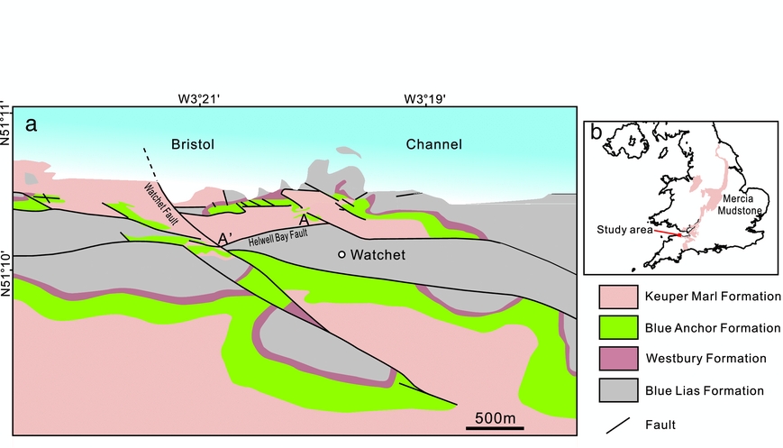
Figure 1. (a) Geological map of the Watchet area and (b) outcrop distribution of the Mercia Mudstone in the UK. Modified from Glen, Hancock & Whittaker (Reference Glen, Hancock and Whittaker2005) and Howard et al. (Reference Howard, Warrington, Ambrose and Rees2008).
3. Methods
We used an integrated field, petrographic and geochemical method to characterize gypsum veins and their host rocks along the cliffs in the study area. Field observations mainly focus on the stratigraphic arrangement of gypsum veins and fractures, the occurrence of evaporite beds, rock colour and lithology. A total of 56 representative samples of gypsum veins from bulk marls and faults, gypsum nodules and rocks from each unit were collected for thin-section and geochemical analysis.
A total of 56 thin-sections of veins were cut normal to vein planes and also fibre plunge directions, so that vein textures and vein-wall contacts could be revealed. We made optical observations of gypsum veins and the host rocks in polarized light microscopy. A gypsum plate is inserted in the optical path between the thin-sections and the polarizing filter, in order to enhance contrast in weakly birefringent gypsum (first-order grey, yellow) and other minerals. Polished thin-sections were also examined using a FEI Quanta 650 FEG scanning electron microscope (SEM). Rock fabric and mineral composition analysis were conducted using energy dispersive X-ray spectroscopy (EDS) that is attached to the SEM.
Elemental concentrations of three gypsum veins in marls, two veins in faults and two gypsum nodules (38 samples) were measured using inductively coupled plasma mass spectrometry (ICP-MS). The samples were dissolved in a mixture of hydrochloric, nitric and hydrofluoric acids, followed by diluting them in 2% nitric acid for measurement on the Elan ICP-MS at the Department of Earth Sciences, University of Oxford. The measurement has a high precision to ±<0.01%. Nine samples were extracted from a 2.9 cm thick gypsum vein every 3.3 mm from one wall to the other, and five samples from a 1.7 cm thick vein. By sampling chemical concentrations across the veins we are able to combine those data with petrographic interpretations of vein widening in order to reconstruct changes in the fluid chemistry during vein widening and cementation. The concentrations of trace and minor elements were analysed in order to evaluate the origin and composition of diagenetic fluids. The strontium concentrations were studied to determine brine palaeosalinity (Kushnir, Reference Kushnir1980, Reference Kushnir1982; Kasprzyk, Reference Kasprzyk2003) and hence sources of vein gypsum.
We also estimated the contents of gypsum cement and gypsum veins in the marls of vein-containing units by analysing SEM images and high-resolution field photos. Box areas of 1 μm2 and 1 m2 were randomly selected in a SEM image and field photo from each unit, respectively. The number of blue pixels in SEM images (white pixels in field photos) was documented using Photoshop software. The ratio of blue (white) versus all pixels represents the content of gypsum.
4. Fracture stratigraphy
Fracture stratigraphy subdivides stratified rock into discrete fracture units defined by properties such as extent, intensity, or some other observed fracture attribute (e.g. the intrinsic types or patterns of cement) (Laubach, Olson & Gross, Reference Laubach, Olson and Gross2009). The Keuper Marl along the cliffs in the study area is divided into five fracture units here according to the occurrence and abundance of gypsum veins (Fig. 2). Each unit is described regarding the spatial distribution and geometry of gypsum veins and the occurrence of gypsum nodules, with correlations to their host-rock types and mineral compositions.
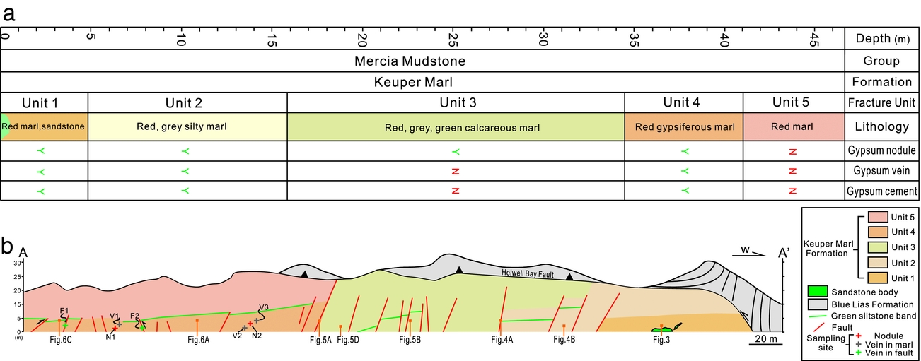
Figure 2. (a) Fracture stratigraphy of the Keuper Marl along the cliffs of the Watchet area. (b) Cross-section along A–A’ showing the fracture units. See location in Figure 1a.
4.a. Unit 1
Unit 1 lies at the base of the outcrop as the oldest unit of the rocks cropping out (Fig. 3). Unit 1 contains an intra-formational pale-grey-green sandstone body at the base. The sandstone body is 8 m long and 1.5 m thick (Fig. 3a). The beds are planar or current-ripple laminated. The sandstone body comprises gypsum cemented sandstone. The sands are medium- to coarse-grained and medium- to well-sorted. The sands exhibit point or linear contacts, with gypsum cementing intergranular pore spaces (Fig. 3c). It has been suggested that the sandstone body probably formed as a brief episode of sand-filled fluvial channels (Hobbs et al. Reference Hobbs, Hallam, Forster, Entwisle, Jones, Cripps, Northmore, Self and Meakin2002). Dense gypsum veins, including subhorizontal veins and steeply dipping veins, are present in the sandstone (Fig. 3b). Gypsum veins are tightly clustered with a spacing of 1–2 cm. Steep veins, which terminate at the sandstone–marl boundary, are confined within the sandstones. Gypsum veins occupy 14.2% of the rock volume (Table 1).
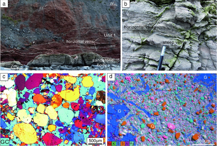
Figure 3. (a) Outcrop photograph showing the sandstone base and red marls of Unit 1. Note the white bands of horizontal gypsum veins. (b) Dense gypsum veins in the sandstone body. (c) Photomicrograph showing the gypsum cement of the sandstone. GC, gypsum cement. Crossed polars, with gypsum plate inserted. (d) EDS image showing fabric and mineral composition of the marl from Unit 1. A – albite; D – dolomite; G – gypsum; K – K-feldspar; Q – quartz.
Table 1. Data for gypsum cement and gypsum vein content (vol.%) in the host rock from non-nodular beds.

Red gypsiferous marls with sub-planar bedding overlie the sandstone body. The marls are rather homogeneous in lithology and consist of apparently structureless mudstone. The marls contain 1–2 cm thick subhorizontal gypsum veins that closely conform to bedding. Vertical spacing of the veins is 80 cm. Multiple nodular gypsum horizons, which are closely spaced, are observed within the central intervals of the unit. The ratio of gypsum vein volume to bulk rock volume is c. 7.1% (Table 1).
The marls mainly contain clay minerals as the matrix. Silt-sized quartz, albite and K-feldspar grains are distributed throughout the marl and are supported by the clay matrix (Fig. 3d). Fine-grained dolomite occurs as discrete patches filling pore spaces. Gypsum, both in the form of isolated needle-like elongate laths and crystal aggregates with indistinct boundaries and irregular shapes, is present in the marls and accounts for 8.7% in volume.
4.b. Unit 2
Unit 2 is a 10.5 m thick interval comprising red, grey and green, highly gypsiferous silty marl (Fig. 4), which is separated from Unit 1 by a 6 cm thick gypsum vein. Two groups of nodular gypsum horizons, each containing four to five horizons (Fig. 4b), occur in this unit. The nodules vary from several centimetres to 2 m in the horizontal dimension, and centimetres to 0.5 m in thickness. Subhorizontal veins and steep veins are intensively developed in this unit, with a spacing of less than one decimetre. The rocks are highly damaged in the siltstone intervals, with the fractures filled with gypsum. The veins exhibit near-random orientations and a high connectivity. Vein intensity is significantly higher in siltstones than in the red marls. Vein spacing is commonly around 5 cm or less. The volume of gypsum veins takes up 25.4% of the total rock volume (Table 1). Interestingly, gypsum veins are much less abundant in the nodular gypsum horizons, especially the horizons between neighbouring nodular horizons (Fig. 4b).

Figure 4. (a) Outcrop photograph showing Unit 2 in the footwall of a normal fault, and Unit 3 in the hanging wall of the fault. Note that gypsum veins are rare in Unit 3, whereas veins are intensively developed in Unit 2. (b) Dense gypsum veins in red marls above nodular gypsum horizons. (c) Highly fractured grey siltstone in Unit 2. All fractures are filled with gypsum. Tape measure is 50 cm. (d) EDS image showing fabric and mineral composition of the silty marl from Unit 2. Cl – clay; G – gypsum; Q – quartz.
The rocks exhibit a variety of fabrics ranging from finely laminated to approximately structureless. Fine siltstones and clay-bearing siltstones in grey, green colours occur at intervals throughout the unit (Fig. 4c). The red marls comprise clay minerals, quartz, gypsum and dolomite (Fig. 4d). The quartz grains are mainly fine-grained and occur either as discrete patches or in closely packed clusters. Overgrowth of quartz is commonly observed, which results in boundary welding of quartz cements. Unit 2 contains a high content (28.2%) of gypsum. Gypsum appears either as pore-filling linear laths or as poikilotopic cements encasing quartz (both detrital grains and cements), dolomite and less commonly clay minerals.
4.c. Unit 3
Unit 3 is characterized by massive red calcareous marls, with planar bedding which is marked by the green marl beds (Fig. 5a–c). Four groups of nodular horizons occur in this unit (Fig. 5b). The lowest group of nodular gypsum horizons is here defined as the boundary of units 2 and 3. The normal faults, which transect the outcrop, are commonly observed to be cemented with gypsum only in the segments adjacent to nodular horizons. In contrast to Unit 2, gypsum veins are not developed in the bulk rock of the nodule-free horizons. The marls are highly fractured, with a horizontal fracture spacing of c. 0.4 m. Many steep opening-mode fractures, including those adjacent to nodular horizons, are exposed in the cliffs and exhibit no signs of cementation by gypsum (Fig. 5c).
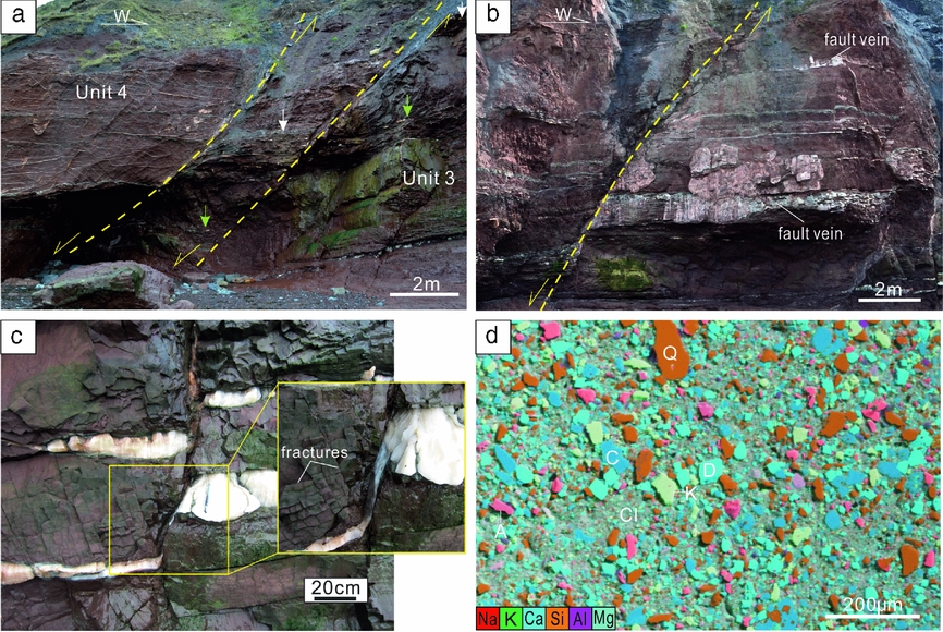
Figure 5. (a) Outcrop photograph showing Unit 3 in the footwall of a normal fault, and Unit 4 in the hanging wall of another normal fault. Note the different levels in vein abundance between units 4 and 3. Arrows mark the horizons that can be correlated. (b) Normal faults partially filled with gypsum in Unit 3. Note that white gypsum fills mainly occur in the segment adjacent to nodular gypsum horizons. (c) Close view of a nodular gypsum horizon. Note the open fractures without gypsum cementation. (d) EDS image showing fabric and mineral composition of the marl from Unit 3. A – albite; C – calcite; Cl – clay; D – dolomite; K – K-feldspar.
The rocks contain clay minerals, quartz, albite, K-feldspar, calcite and dolomite (Fig. 5d). Gypsum is totally absent in the non-evaporite beds. The silt grains of quartz, albite and K-feldspar are poorly sorted and angular. Pore spaces are cemented by calcite and dolomite, with little porosity preserved. Dolomite is commonly present as euhedral rhombs.
4.d. Unit 4
Unit 4 resembles Unit 1 regarding the lithology. This unit is represented by red marls (Fig. 6a, b), and can be distinguished from Unit 3 by a 10 cm thick green siltstone bed and a group of nodular horizons underlying the green bed. Nine nodular gypsum horizons occur in Unit 4. However, gypsum veins are more abundant in the intervals between nodules. Subhorizontal veins and NW–SE-striking, N-dipping veins exhibit a high intensity and connectivity (Fig. 6b). The intensively developed vein network in Unit 4 exhibits a sharp contrast with both the underlying Unit 3 and the overlying Unit 5. Vein spacing is commonly less than 10 cm. Gypsum veins represent 10.3% of the total rock volume (Table 1). The length and height of single veins is often difficult to determine due to the frequent linkage with neighbouring veins. The steep veins terminate abruptly at the level of the topmost nodular gypsum horizon, which bounds Unit 4 and Unit 5.
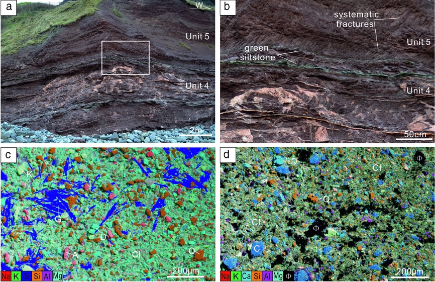
Figure 6. (a) Outcrop photograph showing units 4 and 5; note the absence of veins in Unit 5 and the dense gypsum veins in Unit 4. (b) Close-up view of the boundary between Unit 4 and Unit 5. Note the parallel, systematic fractures in Unit 5, which are parallel to the steep veins in Unit 4, but not filled with gypsum. See location in the box of (a). (e, f) EDS image showing fabric and mineral composition of marl from Unit 4 and Unit 5 respectively. A – albite; C – calcite; Cl – clay; D – dolomite; G – gypsum; Φ – pore space.
The marls consist of clays, quartz, albite, K-feldspar, dolomite and gypsum (Fig. 6c). This unit also contains three green siltstone beds. Silt-sized quartz, albite and K-feldspar are sparsely scattered in the rock matrix of marls, with an average spacing of 30 μm. Fine-grained dolomite fills the pore spaces as the intergranular cements. Gypsum laths, either as discrete individuals or closely packed aggregates, cement the marls, occupying 9.5% of the rock volume (Table 1).
4.e. Unit 5
This unit is present as homogeneous red marls (Fig. 6a, b). Unit 5 and Unit 4 are bounded by a nodular horizon and a laterally impersistent siltstone bed. The striking feature of Unit 5 is the absence of both gypsum nodules and veins. Interestingly, this unit is transected by many NW–SE-striking, N-dipping fractures that are aligned parallel to the steep veins in Unit 4 (Fig. 6b). These fractures are entirely unmineralized.
The marls comprise clays, quartz, albite, calcite and dolomite (Fig. 6d). Gypsum is not found. Quartz and albite are very fine grained. Calcite and dolomite act as the only pore cements. However, apparent pore spaces in varied sizes are commonly observed.
In summary, within units 1 and 4 gypsum veins only occur in the nodular-free intervals, which both contain gypsum cement in the host rock. Nodular gypsum horizons are present in all units except Unit 5. Gypsum veins are mainly concentrated in the nodular horizons that lack gypsum in the host rock. Apparent pore space is only present in Unit 5.
5. Nodule-rooted gypsum veins
In units 1–4 gypsum veins occur in nodular gypsum horizons, which link neighbouring gypsum nodules (Fig. 7). This feature has also been reported by Philipp (Reference Philipp2008). The vein orientations are mainly subhorizontal and parallel to the long axes of the nodules. The veins do not cross-cut the nodules; instead, the veins are rooted in the nodules. Nodule-rooted veins propagated laterally and often coalesced with adjacent veins or nodules, or pinched out in the host rock.
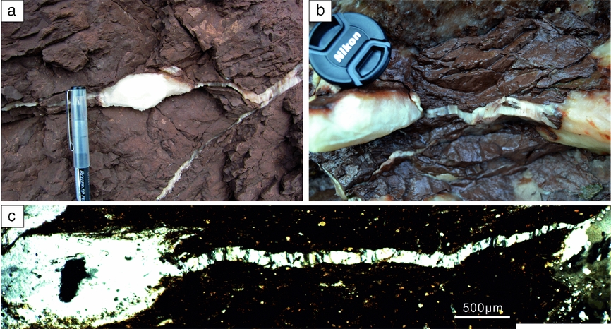
Figure 7. Nodule-rooted horizontal gypsum veins in red marls. (a) Gypsum veins on both the left and right sides of a homogeneous gypsum nodule. (b) A horizontal gypsum vein linking two neighbouring nodules. (c) Photomicrograph showing a gypsum vein linking two nodules. The vein is interpreted to be rooted in the left nodule and to have propagated towards the right nodule, based on the decreased aperture. Crossed polars.
6. Gypsum in the host rock
The distribution of gypsum veins in nodule-free intervals is positively correlated with the presence of gypsum crystals in the host rocks. In clay-rich marls, gypsum is commonly present as sand-sized laths, exhibiting near-random orientations (Fig. 8a). Many sub-parallel gypsum laths are accumulated as aggregates, appearing as blocky gypsum masses. In highly gypsiferous marls, the laths exhibit a high density and connectivity. The original texture seems to be interrupted during diagenesis, as represented by the rotation of the laths. This results in the parallel alignment of the crystals, exhibiting a clear texture. In coarser-grained rocks, including silty marls, clay-rich siltstones and siltstones, gypsum is more diffusely disseminated within the rocks (Fig. 8b). Gypsum exhibits blocky textures and indistinct boundaries, forming poikilotopic cements that support all other grains, including early-formed pore cement of dolomite.
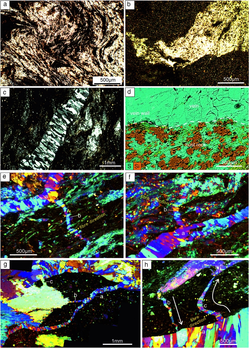
Figure 8. Photomicrographs showing gypsum in the host rock. (a) Dense gypsum laths exhibiting a flowing appearance. (b) Diffusely disseminated gypsum in siltstone; crossed polars. (c) Structureless poikilotopic gypsum cement near a fibrous gypsum vein. (d) EDS image showing widely disseminated gypsum in the wall rock of a gypsum vein. The dashed line marks the vein boundary. (e) A minor gypsum vein ‘b’ linking vein ‘a’ and blocky gypsum masses in clay-rich marl. (f) Vein ‘b’ linking vein ‘a’ and blocky gypsum cements in silty marl. (g) Veins ‘a’, ‘b’ and ‘c’ linking gypsum masses, leading to the segmentation of the host rock. Note that both ends of veins ‘a’ and ‘c’ are rooted in the gypsum masses. (h) Two minor veins (‘b’ and ‘c’) linking a large gypsum vein ‘a’ with a blocky gypsum body. The arrows mark the propagation direction of the minor veins, indicated by the decreased aperture of the veins. The dashed lines mark fibre directions. (e–h) Crossed polars, with gypsum plate inserted.
Crystal aggregates of gypsum laths are commonly present in clay-rich marls around gypsum veins (Fig. 8c). The gypsum laths are typically closely arranged and exhibit a preferred orientation sub-parallel to vein walls. In silty marls, gypsum mainly appears as lenticular blocky masses in the rocks adjacent to gypsum veins. In siltstones gypsum is widely disseminated around gypsum veins. This results in indistinct boundaries of gypsum veins which can be difficult to distinguish from the enclosing gypsum. EDS data demonstrate that gypsum in the wall rock of gypsum veins is commonly attached to vein walls, exhibiting direct contacts with the faces of gypsum crystals in veins (Fig. 8d).
Many minor veins are commonly observed in gypsiferous marl, linking larger veins with blocky gypsum masses in the adjacent areas (Fig. 8e–h). The minor veins are often aligned at high angles to the large veins. Fibres in the minor veins are approximately normal to vein walls (Fig. 8e, f, h). The minor veins are rooted either in the larger veins or in the blocky gypsum masses, with the maximum aperture in the node points and a tapering tip propagating towards the neighbouring gypsum bodies (Fig. 8h). It is interpreted that those minor veins formed as tension gashes during lateral propagation of the large veins. The linkage of veins and gypsum masses often leads to segmentation of the enclosed host rock into multiple segments of varied sizes (Fig. 8g, h).
7. Elemental concentration
The co-precipitation of minor and trace elements into CaSO4 acts as a function of temperature, brine concentration and growth rate (Kushnir, Reference Kushnir1980). Elemental concentrations in gypsum have therefore been extensively studied to evaluate palaeosalinity, the depositional environment, brine origin and diagenetic evolution of the sediments (e.g. Kushnir, Reference Kushnir1980, Reference Kushnir1982; Machel, Reference Machel1985; Lu, Meyers & Schoonen, Reference Lu, Meyers and Schoonen1997; Lu, Meyers & Hanson, Reference Lu, Meyers and Hanson2002; Kasprzyk, Reference Kasprzyk2003). The geochemical measurements reveal that the gypsum nodules and veins are very pure, and many trace elements are below the detection limits (see online Supplementary Table S1, available at http://journals.cambridge.org/geo). The concentrations of Na, Mg and Sr, the commonly studied elements as indicators for palaeoenvironment and palaeosalinity (Kushnir, Reference Kushnir1980; Lu, Meyers & Schoonen, Reference Lu, Meyers and Schoonen1997; Lu, Meyers & Hanson, Reference Lu, Meyers and Hanson2002), are plotted in Figure 9 for nodules, veins (in marl) and fault-related veins. The concentrations of Na and Mg in the three types of gypsum largely overlap. The higher concentration of Na (67 ppm) and Mg (19 ppm) from a gypsum vein sample compared to all other samples (Na < 23 ppm, Mg < 12 ppm) is possibly influenced by fluid or solid inclusions within the vein.
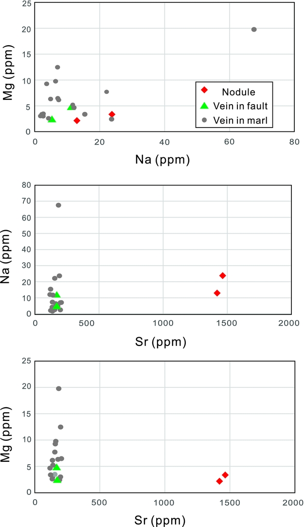
Figure 9. Plot of Na v. Mg, Sr v. Na, Sr v. Mg from samples of gypsum nodules, gypsum veins in marls and gypsum veins in faults. See sample locations in Figure 2b.
Strontium incorporates into the gypsum lattice mainly by substitution of Ca2+ (Ichikuni and Musha, Reference Ichikuni and Musha1978). The equilibrium partition coefficient of strontium increases when the brine concentration rises; strontium concentration has therefore revealed itself most useful as a palaeosalinity indicator (Kushnir, Reference Kushnir1980; Rosell et al. Reference Rosell, Orti, Kasprzyk, Playa and Peryt1998). Both primary and secondary gypsum can be characterized by their strontium content (Leslie, Harwood & Kendall, Reference Leslie, Harwood and Kendall1997; Rosell et al. Reference Rosell, Orti, Kasprzyk, Playa and Peryt1998; Playà, Orti & Rosell, Reference Playa, Orti and Rosell2000; Lu, Meyers & Hanson, Reference Lu, Meyers and Hanson2002). Sr is the sole minor constituent in the structure of gypsum in our samples. The concentrations of Sr of gypsum veins in the bulk marls and faults are similar and generally not differentiable. Importantly, the Sr concentrations from gypsum nodules are one order of magnitude greater than those from the gypsum veins in marls and the fault-related veins (Fig. 9). Such high Sr concentrations in nodules have been suggested to be induced by evaporation in brine lakes during primary deposition of sulphate (Attendorn & Bowen, Reference Attendorn and Bowen1997), and further validate the idea that the nodular gypsum horizons in the Keuper Marl represent the stages of basin drying (Cosgrove, Reference Cosgrove2001).
Single gypsum vein samples are pure in composition and exhibit rather consistent elemental concentrations from one wall to the other (Fig. 10). Sr concentrations are clustered around 150 ppm, which indicates a rather constant brine concentration during precipitation of vein gypsum.
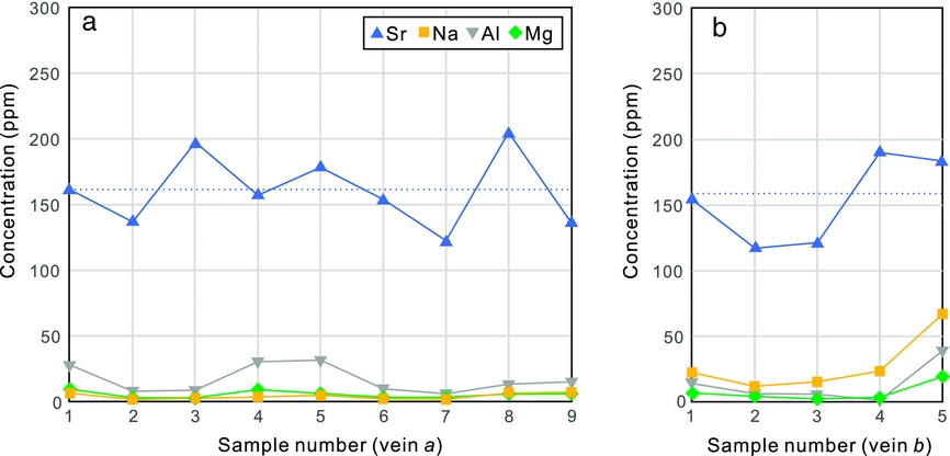
Figure 10. Plot of elemental concentration of Sr, Na, Al and Mg from gypsum vein ‘a’ (a) and vein ‘b’ (b). The dashed line represents the average value of Sr concentration.
8. Discussion
Based on our field and petrographic observations of gypsum veins, elemental analysis of gypsum veins, nodules and fault veins, the discussion mainly focuses on questions regarding the source of vein gypsum, the hydraulic system and the mass transport mode in the low-permeability marls.
8.a. Source of vein gypsum
The formation of gypsum vein networks in the marls of units 1, 2 and 4 would be expected to require vast quantities of gypsiferious solutions for vein-filling due to the low solubility of gypsum (Shearman et al. Reference Shearman, Mossop, Dunsmore and Martin1972). A common feature of those veins is that they are predominantly concentrated in non-nodular intervals.
The presence of gypsum veins in non-nodular beds has been reported in previous studies (Shearman et al. Reference Shearman, Mossop, Dunsmore and Martin1972; Gustavson, Hovorka & Dutton, Reference Gustavson, Hovorka and Dutton1994; Mohamed El Tabakh & Warren, Reference Mohamed El Tabakh and Warren1998; Cosgrove, Reference Cosgrove2001; Rustichelli et al. Reference Rustichelli, Di celma, Tondi, Baud and Vinciguerra2016). Gypsum-filling of fractures has been largely attributed to externally sourced gypsum (Shearman et al. Reference Shearman, Mossop, Dunsmore and Martin1972; Machel, Reference Machel1985; Gustavson, Hovorka & Dutton, Reference Gustavson, Hovorka and Dutton1994). It has been suggested that the excess gypsum, produced during anhydrite–gypsum transition, could have been delivered from more deeply buried dissolving evaporite beds to adjacent non-evaporite beds (Shearman et al. Reference Shearman, Mossop, Dunsmore and Martin1972; Philipp, Reference Philipp2008). Gypsum-rich fluids could then be focused into high-permeability pathways of tensile fractures in the mudstone. Those fractures could be simultaneously generated by the injection of gypsum-rich fluids (Shearman et al. Reference Shearman, Mossop, Dunsmore and Martin1972; Philipp, Reference Philipp2008) or have formed as pre-existing fractures that facilitated high-salinity fluids entering the adjacent non-evaporite beds (Gustavson, Hovorka & Dutton, Reference Gustavson, Hovorka and Dutton1994). Gypsum from an external source could then precipitate in those fractures and cause the final sealing of them. However, this hypothesis lacks supporting evidence from vein host rocks.
Our observations demonstrate that subhorizontal gypsum veins are commonly present in all nodule-bearing units and link neighbouring nodules (Fig. 7). Those veins are interpreted to be sourced by their host nodules during anhydrite hydration (Fig. 11). Nodule-rooted fractures, which could result from tensile stress concentration at the lateral margins of nodules (Philipp, Reference Philipp2008), were filled with excess gypsum derived from nodules. Crystallization pressure of gypsum, up to 15 MPa (Keulen, Den Brok & Spiers, Reference Keulen, Den Brok and Spiers2001), could lead to host-rock rupturing and fracture propagation. An external source for gypsum in non-nodular beds is considered unlikely due to the following reasons.
(1) Abundant non-filled fractures are present in non-evaporite horizons adjacent to nodular horizons in Unit 3 (Fig. 5c). This suggests that those fractures were not produced by brecciating of the surrounding rocks by anhydrite–gypsum transition, and the nodular gypsum did not necessarily provide gypsum sources for fractures in adjacent beds.
(2) It is difficult to explain why fractures in Unit 5 are not filled, whereas Unit 4 contains dense veins (Fig. 6a, b), if it is assumed that gypsum-rich fluids were advectively transported into these beds.
(3) The much lower (approximate one order of magnitude) Sr concentrations of gypsum veins compared to gypsum nodules (Fig. 9) indicate that the nodules are possibly not the nutrient source for veins. This is because Sr is not appreciably fractionated by sulphate crystallization (Mohamed El Tabakh & Warren, Reference Mohamed El Tabakh and Warren1998).
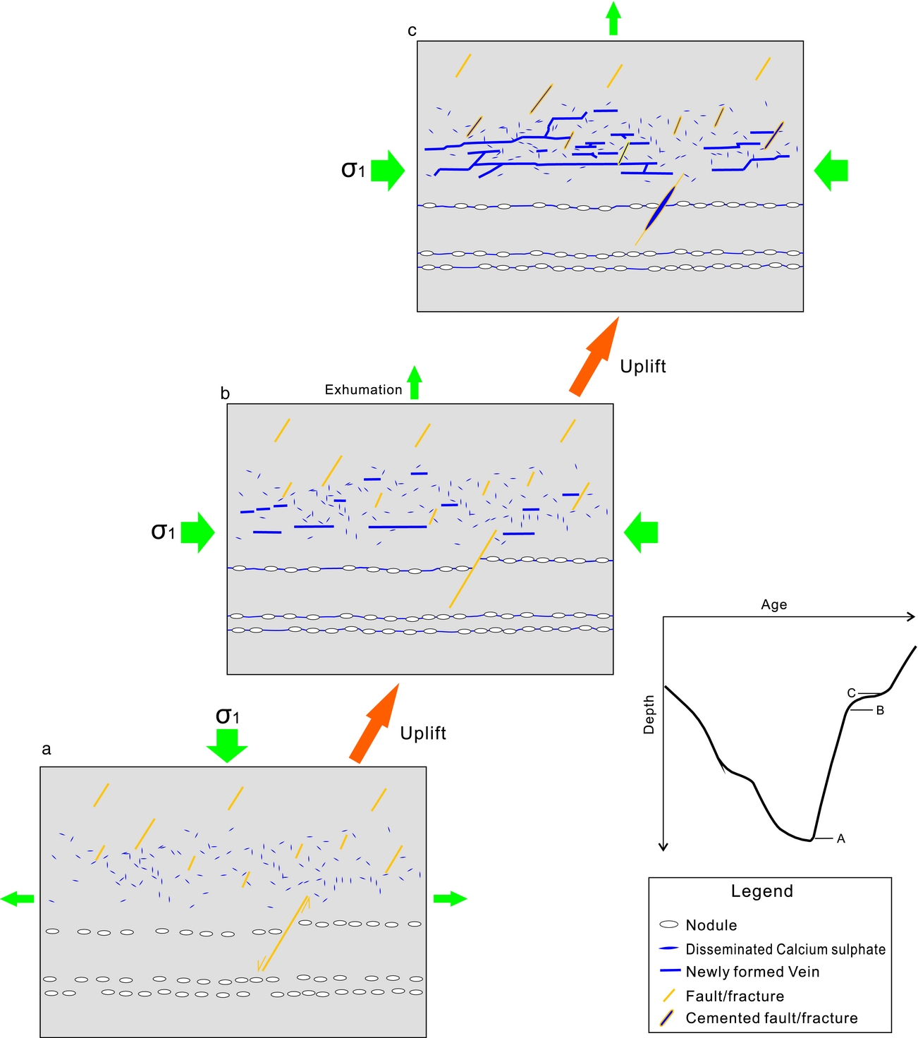
Figure 11. Sketch illustrating the diagenetic processes of calcium sulphate during uplift of the Keuper Marl. (a) Burial anhydrite in the form of discrete laths and nodules at the maximum depth. (b) Onset of anhydrite hydration during uplift of the marl. Note the formation of nodule-rooted veins. (c) Precipitation of gypsum in both the pre-existing fractures and newly formed hydraulic fractures. Gypsum is transported to adjacent veins mainly through diffusion after fracture initial propagation. Note that fractures in gypsum-free rocks are not filled. The burial curve is modified from Cosgrove (Reference Cosgrove2001).
Given the fact that gypsum cement, either in the form of elongate laths or diffusely disseminated blocky gypsum, coexists with gypsum veins in non-nodular beds, it is instead proposed that the local gypsum cement could have provided the source of calcium sulphate for the filling of adjacent veins. This idea is also evident from the contents of gypsum cement and gypsum veins in the host rock (Table 1), where a higher content of gypsum cement in the host rock corresponds to a higher content of gypsum veins. In this case, fractures could be filled by locally derived gypsum only in the bulk rocks containing gypsum cements. This is especially clear in units 3 and 5, which lack gypsum veins and cements but contain abundant non-filled fractures (Figs 5c, 6b).
Based on the evidence above, the local source of gypsum is argued to be responsible for the filling of adjacent fractures as a result of redistribution of gypsum already present in the rock (Fig. 11).
8.b. Hydraulic fracturing
The heterogeneous distribution of veins in the rather homogeneous Keuper Marl suggests that the diagenetic fluids are unlikely to be circulated from underlying evaporite beds for two main reasons.
(1) Gypsum veins are absent from units 3 and 5, but are abundant in all other units. If the diagenetic fluids were from underlying evaporites, then surely the veins would be expected to exhibit a more homogeneous distribution in all fracture units. If the barren fractures in units 3 and 5 formed later than the gypsum veins, it is expected that such fractures would also occur in Unit 4 and could cross-cut the gypsum veins. However, all fractures in Unit 2 are filled with gypsum, indicating that fracture cementation post-dates the formation of the barren fractures. The barren fractures, especially those parallel-aligned fractures in Unit 5, are therefore interpreted to pre-date fracture cementation in vein-bearing units.
(2) Local faults, which penetrate into the fracture units without gypsum veins, only contain a filling of gypsum in the segments adjacent to nodular horizons (Fig. 5a–c). This observation does not favour a long-distance brine migration along faults, and therefore does not support the idea (Philipp, Reference Philipp2008) that faults acted as the main fluid migration paths.
The stratigraphic arrangement of gypsum veins, that is, localized in units 1, 2 and 4, indicates that the diagenetic fluids are more likely to be a mix of connate and meteoric waters. The input of low-salinity meteoric waters could also contribute to the decrease in the partition coefficient of strontium, and result in the relative low concentrations of Sr in vein gypsum. When the sediments were uplifted to shallow depths of the telogenetic zone, the marls would have come in contact with low-salinity, low-temperature waters. Meteoric water is highly undersaturated with gypsum or anhydrite and will readily dissolve those calcium sulphates (Dronkert, Reference Dronkert1987). This would result in anhydrite dissolution. However, not all sulphates have been dissolved because of the slow dissolution kinetics.
A pervasive increase in fluid pressure in the marl was a response to the tectonic compression that facilitated the formation of hydraulic fractures and subsequent generation of veinlets (Cosgrove, Reference Cosgrove and Ameen1995, Reference Cosgrove2001). The newly formed hydraulic fractures are considered as internal hydraulic fractures rather than intrusion hydraulic fractures (Engelder & Lacazette, Reference Engelder, Lacazette, Barton and Stephansson1990; Mandl, Reference Mandl2005, p. 27). Otherwise, it would be necessary to invoke a selective penetration of gypsum-rich brines into certain units and to completely bypass other units. The internal hydraulic fractures mainly include subhorizontal bedding-parallel fractures which took advantage of bedding fissures with low tensile strengths (Shearman et al. Reference Shearman, Mossop, Dunsmore and Martin1972), and also bedding planes that diverted propagation of opening mode fractures (Gale et al. Reference Gale, Laubach, Olson, Eichhubl and Fall2014; Lee et al. Reference Lee, Olson, Holder, Gale and Myers2015). The pre-existing fractures, such as the N-dipping, steep fractures, were reactivated and also filled with secondary gypsum.
8.c. Mass transport
In clay-rich rocks of low permeability, containing more prevalent fibrous mineral veins than other rock types (Cobbold et al. Reference Cobbold, Zanella, Rodrigues and Loseth2013), diffusion has been considered as the dominant mass-transport mechanism (Wiltschko & Morse, Reference Wiltschko and Morse2001; Lander & Laubach, Reference Lander and Laubach2015). Although diffusion is only effective within a small scale (centimetres) in rocks (Bickle & McKenzie, Reference Bickle and McKenzie1987), diffusion could produce fibrous veins with an aperture up to 10 cm (Fisher et al. Reference Fisher, Brantley, Everett and Dzvonik1995) accompanied by the depletion of the vein-forming elements in the surrounding rocks. For gypsum veins in the low-permeability Keuper Marl, we argue that the mass transport from sites of material source to gypsum veins occurred via a combined local advection during hydraulic fracturing, and diffusion after the initial stage of fracture propagation. When hydraulic fractures were opened against the least principle stress by fluid injection, advective fluids were sucked into the fractures due to the pressure difference between the fracture and the wall rock. This could have led to a much more effective mass transfer due to the high permeability the fractures provide (Oliver & Bons, Reference Oliver and Bons2001; Laubach et al. Reference Laubach, Reed, Olson, Lander and Bonell2004).
However, upon fracturing a rapid drop of pressure and pressure-dependent mineral solubility would occur (Phillips, Reference Phillips1972; Henderson & McCaig, Reference Henderson and McCaig1996), leading to precipitation of gypsum on fracture walls and a final complete fracture sealing. The sealing of fractures eliminates the possibility of long-distance mass transfer; however, the pressure difference between the host rock and the thin fluid film on vein–wall interfaces could lead to gypsum transported to adjacent vein walls diffusively (Putnis, Prieto & Fernandez-Diaz, Reference Putnis, Prieto and Fernandez-Diaz1995; Bons, Elburg & Gomez-Rivas, Reference Bons, Elburg and Gomez-Rivas2012). The lack of crack-seal textures in the gypsum veins suggest that those veins grew incrementally without repeated re-opening events (Bons, Reference Bons2000). The constant elemental concentrations in single gypsum veins suggest that the vein-filling gypsum was possibly derived from a uniform source. This source is constrained to be the local gypsum cement in adjacent rocks (Fig. 11), evident from the concentration of disseminated gypsum in the wall rocks and also its direct contacts with vein gypsum. The primary rock fabrics have been modified by the diagenesis and redistribution of gypsum as expressed by the distortion and accumulation of gypsum crystals, towards stability within the ambient temperature and pressure regime (Dronkert, Reference Dronkert1987). The transport distance is very low, presumably at decimetre scale. This is evident from the rocks adjacent to the boundary of units 4 and 5; the lower unit contains widespread gypsum whereas the upper units do not contain gypsum in either the fractures or the rock matrix. A dominance of diffusion rather than advection could then be expected to account for mass transport.
In summary, the mass transport of gypsum is mainly through fluid advection during hydraulic fracturing, while veins derived their gypsum mainly by diffusion after the initial fracture propagation.
9. Conclusions
(1) The Keuper Marl cropping out in the Watchet area is subdivided into five fracture units. Disseminated gypsum as cement in the rocks is observed to coexist with the development of gypsum veins in non-nodular beds.
(2) Gypsum veins in marls and faults exhibit much lower Sr concentrations than those from gypsum nodules.
(3) The nodule-rooted horizontal gypsum veins are sourced by excess gypsum from nodules in the evaporite beds. Differently, the gypsum veins in non-nodular beds derived nutrients from local gypsum cements in the surrounding host rocks.
(4) The subhorizontal veins in non-nodular beds formed as hydraulic fractures. The diagenetic fluid is a mix of connate water and meteoric water rather than brines from nodular horizons.
(5) Gypsum was transported to walls of adjacent sealed gypsum veins through diffusion over a short distance and was rarely transported to beds containing no depositional gypsum, leaving fractures in those beds unfilled.
(6) This study implies that fracture cementation by minerals in low-permeability rocks can is highly dependent upon the presence of the same phase in the host rock.
Acknowledgements
This research is funded by Shell International Exploration and Production B.V. We thank Jon Wells for sample preparation and Owen Green for assistance with microscope imaging. Alex Dickson is thanked for assistance with geochemical measurements. We appreciate the editorial handling of this paper by Olivier Lacombe. Reviews by two anonymous reviewers significantly improved the quality of this paper.
Supplementary material
To view supplementary material for this article, please visit https://doi.org/10.1017/S001675681700070X.


