1. Introduction
1.a. Purpose of the study
Synsedimentary deformation in alluvial deposits has been widely studied around the world since it reflects distinct geological processes other than sedimentation. Different genetic mechanisms for deformation structures have been identified and interpreted both on a regional and a local scale: (i) tectonic structures sensu stricto generated by regional tectonic processes and consistent with regional stress fields (e.g. Blissenbach, Reference Blissenbach1954; Bull, Reference Bull1968; Nemec & Steel, Reference Nemec and Steel1988; Mastalerz & Wojewoda, Reference Mastalerz, Wojewoda, Marzo and Puigdefábregas1993); (ii) soft-sediment deformation structures produced by liquefaction mostly linked to propagation of seismic waves (e.g. Seilacher, Reference Seilacher1969, Reference Seilacher1984; Hempton & Dewey, Reference Hempton and Dewey1983; Davies, Turner & Sansom, Reference Davies, Turner and Sansom2004; Gruszka & Loon, Reference Gruszka and Loon2007); (iii) diapiric structures produced by migration of evaporites or plastic lutites (mud diapirs) (e.g. Morgan, Coleman & Gagliano, Reference Morgan, Coleman, Gagliano, Braunstein and O’Brien1968; Simón & Soriano, Reference Simón and Soriano1986); (iv) karst subsidence structures, reflecting either slow sinking or a sudden collapse of sediments overlying karstified rocks (e.g. Soriano & Simón, Reference Soriano and Simón1995; Beck, Reference Beck and White2004; Waltham, Bell & Culshaw, Reference Waltham, Bell and Culshaw2005; Gutiérrez, Guerrero & Lucha, Reference Gutiérrez, Guerrero and Lucha2008); and (v) ice wedge casts and other structures induced by periglacial processes (e.g. van Vliet-Lanoë, Magyari & Meilliez, Reference van Vliet-Lanöe, Magyari and Meilliez2004; Briant et al. Reference Briant, Bateman, Coope and Gibbard2005).
Most research on this subject has generally focused on the study of individual geological processes; relatively few studies have been dedicated to understanding the relationship and interaction between different genetic types. The present paper aims to contribute to the literature on multiple relationships between faulting, karst subsidence, diapirism and sedimentation. Synsedimentary tectonic, karstic and diapiric structures affecting alluvial and aeolian deposits coexisted in the central Ebro Basin (Fig. 1a, b) during early Pleistocene time, resulting in a complex stratigraphical architecture. The main aim of this work is to discriminate between each intervening process and interpret how they interact by using geological and geophysical techniques. The results may be applied to other areas with similar deformational setting, either at similar or larger scales. The example described is proposed as an analogue model that could successfully illustrate evolution patterns of basins of potential interest for petroleum geology where similar processes have developed.

Figure 1. (a) Location of the study area in the Iberian Peninsula. (b) Geological map of the central Ebro Basin. (c) Aerial orthoimage (Instituto Geográfico Nacional, Spanish Government) showing the studied quarry in 2012, with location of cross-sections of Figure 3 and locations of geophysical surveys.
1.b. Background
A large number of studies carried out during the last decades have focused on diapiric and karstic deformations affecting the Quaternary alluvial deposits that overlie Early–Middle Miocene lutites and evaporites of the central Ebro Basin. Simón & Soriano (Reference Simón and Soriano1986) identified two types of diapiric structures (dome and piercing) affecting the oldest terraces of the Ebro River, the latter being associated with contractional structures (high-angle faults and monoclines). Benito & Casas (Reference Benito and Casas1987) described a third type (dome-piercing) in the Gállego and Ebro river terraces, developed during or very soon after deposition. Studies devoted to deformations associated with palaeokarst have allowed ductile synsedimentary structures to be characterized, as well as brittle postsedimentary structures developed in partially lithified sediments (Soriano & Simón, Reference Soriano and Simón1995; Benito et al. Reference Benito, Pérez-González, Gutiérrez and Machado1998; Gutiérrez, Guerrero & Lucha, Reference Gutiérrez, Guerrero and Lucha2008).
According to Simón & Soriano (Reference Simón and Soriano1985, Reference Simón and Soriano1986), Benito et al. (Reference Benito, Pérez-González, Gutiérrez and Machado1998), Soriano & Simón (Reference Soriano and Simón1995) and Arlegui & Simón (Reference Arlegui and Simón2000) in the Ebro Basin, the following criteria can be used for distinguishing between tectonic, karstic and diapiric structures. (i) As karstic and diapiric structures are due to local vertical mass movement, they display cylindrical or conical 3D geometry with curved rupture patterns concentric with respect to the sinking or rising centre. (ii) Karstic and diapiric deformation usually only affects shallow levels, without any imprint on deeper rocks. (iii) Karstic and diapiric deformation structures usually have a significant ductile component and frequently result in loss of the original sedimentary textures and structures. (iv) Intrusive boundaries of piercing diapirs and karst–subsidence ruptures are represented by either normal, reverse or vertical contacts showing random strike. In contrast, tectonic faults show persistent orientations controlled by the regional stress field. In the case of the Ebro Basin, these are normal faults showing two preferred directions: one close to N–S (coherent with the regional extensional stress field) and another one to WNW–ESE (induced by inherited faults affecting the underlying Miocene rocks).
Little attention has been paid to understanding the relationships (and hypothetic interaction) between tectonic, diapiric and karstic deformation as well as between these processes and coeval sedimentation. Simón & Soriano (Reference Simón and Soriano1986) provide examples of Quaternary diapirs locally triggered by tectonic normal faults in the central Ebro Basin. Benito & Casas (Reference Benito and Casas1987) suggest a relationship between diapiric structures and alluvial deposits thickened by karst subsidence: rapid loading in subsiding areas leads to high fluid pressure in fine-grained sediments and hence to gravitational instability and intrusion.
Such interactions have also been evidenced in other regions. Triggering of diapirs by faulting has been demonstrated by means of conceptual and analogue models (e.g. Vendeville & Jackson, Reference Vendeville and Jackson1992; Jackson, Vendeville & Schultz-Ela, Reference Jackson, Vendeville and Schultz-Ela1994; Guglielmo, Jackson & Vendeville, Reference Guglielmo, Jackson and Vendeville1997), as well as by regional studies (e.g. Pflug, Reference Pflug1973). Calaforra & Pulido-Bosch (Reference Calaforra and Pulido-Bosch1999) suggest that the presence of diapirs determines both the lithological and the hydrogeological setting at shallow levels, and hence the distribution and typology of large karstic forms in the Triassic lutites and evaporites in the Betic Chains (Spain). Looff & Looff (Reference Looff and Looff2000) analysed the interaction between karst subsidence, piping and salt domes in the Gulf Coast, revealing that surface subsidence can occur above a shallow salt diapir due to the differential movement of the underlying salt. Further, extensional deformation of the strata overlying a salt diapir can produce a variety of fault patterns which in turn could control subsidence.
When occurring in an active sedimentary basin, these deformation types can interact with sedimentation. Synsedimentary unconformities (growth strata) are the major effects of local tectonics. They were first described at a basin scale by Riba (Reference Riba1976) and subsequently observed by other authors (e.g. Anadón et al. Reference Anadón, Cabrera, Colombo, Marzo, Riba, Allen and Homewood1986; Muñoz & Casas, Reference Muñoz and Casas1997; Aschoff & Schmitt, Reference Aschoff and Schmitt2008). At a small scale, sediments deposited against a rising fold or fault are uplifted, deformed and eroded by continuous movement, occasionally drawing growth strata. These synsedimentary geometries have been described in relation to tectonic deformation (e.g. Miall, Reference Miall1996), diapirism (e.g. Banham et al. Reference Banham, Mountney, Kane, McCaffery, Bádenas, Aurell and Alonso-Zarza2011) or karst subsidence (e.g. Purdy, Reference Purdy1974; Gustavson, Reference Gustavson1986; Ford, Reference Ford1997; Dogan, Reference Dogan2005; Luzón et al. Reference Luzón, Pérez, Soriano and Pocoví2008; Silva et al. Reference Silva, López Recio, González Hernández, Tapias, Alarcón, Cuartero, Expósito, Lázaro, Manzano, Marín, Morín and Yravedra2008).
2. Geological and geomorphological setting
The studied area is located in the central part of the Cenozoic Ebro Basin (NE Spain), c. 25 km ESE of Zaragoza city (Fig. 1b). This basin is bounded by the Pyrenees to the north, the Iberian Range to the south and the Catalonian Coastal Range to the east. In its central part, the thickness of the Palaeogene and Neogene series reaches 1500 m (Riba, Reguant & Villena, Reference Riba, Reguant, Villena and Comba1983). The Ebro Basin constitutes the last stage in the evolution of the southern foreland basin of the Pyrenees, and its general structure was achieved between the Late Oligocene and Early Miocene (Pardo et al. Reference Pardo, Arenas, González, Luzón, Muñoz, Pérez, Pérez Rivarés, Vázquez-Urbez, Villena and Vera2004).
By Late Eocene times, the connection between the Ebro Basin and the Atlantic Ocean was closed and the sedimentation became only continental. During this stage, alluvial fan systems (sourced in the three mountain ranges) and shallow evaporite and carbonate lacustrine systems developed (Muñoz et al. Reference Muñoz, Arenas, González, Luzón, Pardo, Pérez, Villena, Gibbons and Moreno2002; Pardo et al. Reference Pardo, Arenas, González, Luzón, Muñoz, Pérez, Pérez Rivarés, Vázquez-Urbez, Villena and Vera2004). Most of the exposed rocks correspond to terrigenous, evaporite (mainly gypsum and halite) and carbonate facies deposited in these sedimentary environments.
Endorheic sedimentation ended by Late Miocene times (12.5–8.5 Ma) as the Ebro Basin opened towards the Mediterranean Sea (García-Castellanos et al. Reference García-Castellanos, Vergés, Gasper-Escribano and Cloetingh2003). A vast drainage system was established, eroding Miocene rocks while favouring Quaternary fluvial and alluvial sedimentation. Cold climate conditions during Pleistocene time favoured the development of proglacial alluvial plains in the Ebro Basin (Luzón et al. Reference Luzón, Rodríguez-López, Pérez, Soriano, Gil and Pocoví2012). Glacial episodes were punctuated by warmer stages; such climatic fluctuations gave rise to a number of stepped terrace and pediment levels.
In the central sector of the Ebro Basin, Soriano (Reference Soriano1990) recognized eight terrace levels mainly developed in the right bank of the Ebro River (from the youngest, T1 to the oldest, T8). The recent terrace levels are well preserved and of kilometres in length, whereas remnants of variable size of the older terraces are only maintained on top of hills and mesas. The thickness of terraces falls within the range 5–25 m, although drills show local thicknesses in excess of 45 m (Guerrero, Gutiérrez & Lucha, Reference Guerrero, Gutiérrez and Lucha2004). The terrace deposits mainly comprise polygenic gravels with interbedded sands and silts. The gravels show horizontal bedding, cross-bedding (planar and trough) and clast imbrication. Scattered bands of Mn and Fe precipitates, as well as carbonate crusts at the top of the Quaternary deposits, appear frequently.
Stepped pediments (six levels; Soriano, Reference Soriano1990) are also identified in this area. The thickness of pediment deposits usually ranges from 1 to 6 m, although outcrops with 12 m of accumulated sediments have also been observed locally. Pediment deposits comprise sand, silt and angular to subangular gravel. Gravel structure is generally massive although horizontal bedding, imbricated clasts, low-angle cross-bedding and channel fill deposits have been recognized.
In general, the underlying Miocene beds are nearly horizontal or gently deformed by folds and faults (Quirantes, Reference Quirantes1978; Arlegui & Simón, Reference Arlegui and Simón2001). Tectonic deformation and stress fields in the central Ebro Basin during Neogene and Quaternary times were analysed by Arlegui & Simón (Reference Arlegui and Simón2000, Reference Arlegui and Simón2001). According to these works, outcrop-scale faults and fractures within the Ebro Basin can be grouped into two main sets: (i) a N–S-striking older set developed under an intraplate stress field with S Hmax oriented approximately N–S, related to forces caused by the convergence of Africa, Iberia and Europe and rifting at the Valencia trough; and (ii) a NW–SE- to E–W-striking younger set related to extensional deformation caused by differential isostatic movement at the Pyrenees and its foreland basin. A closer look at the first set shows that it is frequently split into NNW–SSE and NNE–SSW maxima. This is consistent with the recent to present-day tectonic setting of eastern Iberia, characterized by both spatial transition and time shifting between regional stress fields with NNW–SSE and NNE–SSW S Hmax (Simón, Reference Simón1989, Reference Simón2006; Cortés et al. Reference Cortés, Liesa, Simón, Casas, Maestro and Arlegui1996; Andeweg et al. Reference Andeweg, De Vicente, Cloething, Giner and Muñoz-Martín1999; Herraiz et al. Reference Herraiz, de Vicente, Lindo-Ñaupari, Giner, Simón, González-Casado, Vadillo, Rodríguez-Pascua, Cicuéndez, Casas, Cabañas, Rincón, Cortés, Ramírez and Lucini2000). A detailed study of satellite images by Arlegui & Soriano (Reference Arlegui and Soriano2003) shows that the aforementioned dominant directions are expressed on a regional scale as tectolineaments both in Miocene and Quaternary materials.
One of the most active geological processes in this region today is gypsum karst, represented by numerous alluvial dolines that cause frequent damage to urban areas (Soriano & Simón, Reference Soriano and Simón1995, Reference Soriano and Simón2002; Guerrero, Gutiérrez & Lucha, Reference Guerrero, Gutiérrez and Lucha2004; Pueyo-Anchuela et al. Reference Pueyo-Anchuela, Casas-Sainz, Soriano, Pocoví-Juan, Ipas-Lloréns and Ansón-López2010; Soriano et al. Reference Soriano, Luzón, Yuste, Pocoví, Pérez, Simón and Gil2012). Moreover, syn- and postsedimentary palaeodolines appear in quarries and trenches open in the Quaternary deposits (Luzón et al. Reference Luzón, Pérez, Soriano and Pocoví2008, Reference Luzón, Pérez, Pocoví, Soriano, Gil, Rodríguez-López and Simón2011; Soriano et al. Reference Soriano, Luzón, Yuste, Pocoví, Pérez, Simón and Gil2012). Locally, dissolution has caused strong aggradation of terraces and channel adjustments as in the oldest terraces of the Gállego River (Benito et al. Reference Benito, Pérez-González, Gutiérrez and Machado1998; Benito, Pérez-González & Machado, Reference Benito, Pérez-González and Machado2000).
3. Methodology
After intense fieldwork over the central Ebro valley, a large quarry was selected for detailed study (Fig. 1c). The criteria for quarry selection included good-quality, large-sized and diversely oriented exposures, as well as wide variety of facies and deformation structures. All these features allow a more complete view of the processes under investigation.
The general structure of the work is described by the logic tree of Figure 2. First, karstic, tectonic and diapiric structures need criteria to distinguish them as well as a common methodology for their structural analysis. Second, the interaction between and triggering of these structures should be explained by either kinematical or mechanical models. Finally, the complex sedimentary architecture is only understood from the interaction between deformation and sedimentation. Consequently, this study requires a multiproxy approach including diverse techniques as described in the following sections.
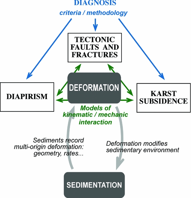
Figure 2. Conceptual and methodological scheme of the present study.
3.a. Geological analysis to characterize materials and structures
The sedimentological study aims to define, describe and interpret the main facies associations. Several lithofacies and architectural elements, in the sense of Miall (Reference Miall and Miall1978, Reference Miall1996), have been defined in the area. Grain size analyses were made by dry sieving, using set-screens selected at 1/4 ϕ intervals. After being dried at 100°C, the samples were put into a sieve tower and shaken for 20 minutes in an AMP0.40 W220 HZ59 device.
Analysis of deformation structures (independently of their assumed origin) has followed a standard protocol based on exhaustive outcrop observation, elaboration of detailed cross-sections, measurement of displacements and the orientation of structural elements, projection onto equal-area stereoplots and kinematical reconstruction. The diagnostic interpretation of the origin of deformation structures has been based on the criteria listed above.
3.b. Geophysical analysis to approach the 3D geometry of deformation structures
A magnetometric survey (intensity and gradient of the magnetic field) was performed using two different devices: a proton magnetometer-gradiometer (PMG-01 from GF Instruments), taken as base for diurnal variation, and a magnetometer (GSM-19 from GEM-System) with GPS.
Electromagnetic radiation (EM) allowed measurement of the apparent conductivity and susceptibility of subsoil materials. Orthogonal profiles spaced 1 m apart were performed over the whole quarry floor, using a multifrequency electromagnetic sensor (GEM-02–163 device from GEM-System) with frequencies ranging from 330 Hz to 24 kHz.
A ground-penetrating radar (GPR) survey of the quarry floor (along profiles parallel to the main walls) and berms was made with a Ramac-GPR device provided with 50 and 100 MHz antennas.
4. Stratigraphy and sedimentology
A series of Pleistocene terrigenous deposits of thickness c. 60 m is exposed in the studied quarry. They belong to the oldest terrace of the Ebro River (T8 level according to Soriano, Reference Soriano1990) located at 210 m above the talweg. This terrace has been traditionally attributed to the Early Pleistocene based on its geomorphological position (Benito et al. Reference Benito, Pérez-González, Gutiérrez and Machado1998; Marqués et al. Reference Marqués, Santos, Esnaola and Gil Marín1998; Colomer et al. Reference Colomer, Navarro, Hernández and Ramírez2006). A recent magnetostratigraphic study assigns it to the Matuyama chron, i.e. older than 773 ka (Gil et al. Reference Gil, Pueyo, Palma-Rodrigues, Soriano, Luzón, Pocoví, Pérez and Yuste2013b ).
The stratigraphic series is strongly deformed, and internal angular unconformities are locally observed (Fig. 3). These discontinuities were the basis for defining five stratigraphic units. Faults affecting each unit are generally covered by the overlying unit. Broadly continuous (up to several metres) thick bodies of siliceous and carbonate gravels (mainly pebbles and cobbles) showing horizontal stratification predominate. Gravels are interbedded with mainly wedge-shaped sandy intervals that show a wide variety of sedimentary structures. Lutites are rarely present. The general stratigraphic succession of the studied outcrop is shown in Figure 4.

Figure 3. (a, b) Photographs and schematic cross-sections of the two main quarry faces (see location in Fig. 1c). 1, 2, 3, 4, 5: stratigraphic units; D: diapir.
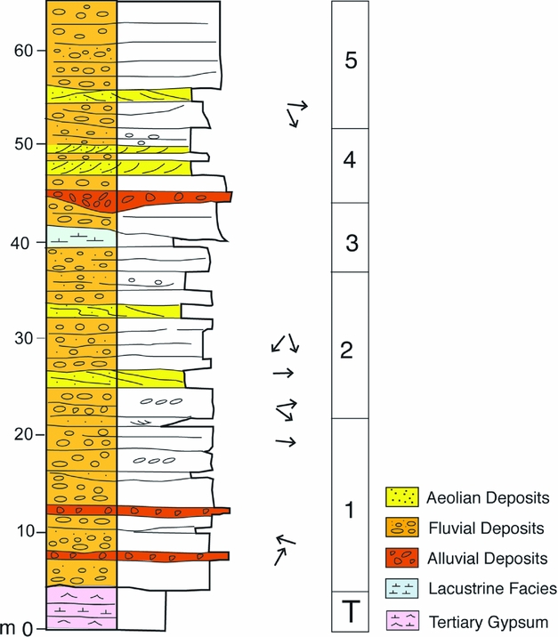
Figure 4. General stratigraphic sequence.
The sedimentological study of these deposits (Luzón et al. Reference Luzón, Rodríguez-López, Pérez, Soriano, Gil and Pocoví2012) has revealed that water and wind processes interfered in an outwash plain where meltwater flow favoured gypsum dissolution and subsidence. Water-related facies associations are mainly longitudinal gravel bars, while dune sands and sandsheets are the most typical aeolian deposits.
4.a. Architectural elements
4.a.1. Longitudinal gravel bars
These are represented by wide tabular bodies of gravels up to 3 m thick limited by planar or slightly irregular erosive surfaces. Interbedded wedge-shaped or lenticular sandy intervals are locally present. Grain-supported gravels show crude horizontal bedding due to textural changes (Fig. 5a, b). Well-sorted, rounded to subrounded siliceous and carbonate pebbles and cobbles derived from both the Iberian and the Pyrenean ranges predominate, but angular to subangular carbonate cobbles and boulders are also locally present (Fig. 5c). The latter are clearly derived from reliefs of Tertiary rocks close to the study zone. Imbrication is a common feature. Interbedded medium- to fine-grained sand levels are up to 40 cm in thickness and show horizontal lamination and rare cross-lamination. If present, they constitute the upper part of fining-upwards cycles. Gravel deposits represent tractive processes and the development of longitudinal bars in shallow gravel-bed braided channels, where conditions of rapid gravel transport favoured low-relief bars (Hein & Walker, Reference Hein and Walker1977; Rust, Reference Rust and Miall1978; Miall, Reference Miall and Miall1978, Reference Miall1996; Steel & Thompson, Reference Steel and Thompson1983; Shukla, Reference Shukla2009; Soreghan et al. Reference Soreghan, Soreghan, Sweet and Moore2009). Upward-fining cycles reflect bar accretion during waning discharges or lateral migration of channel ward-dipping bar margins (Smith, Reference Smith1974; Miall, Reference Miall1996).

Figure 5. (a, b) Longitudinal gravel bars. They are mainly integrated by well-sorted rounded to subrounded siliceous and carbonate pebbles and cobbles. (a) Horizontal stratification, mainly due to textural changes, characterizing the longitudinal gravel bars. (b) Differences in the sandy matrix content between gravel beds are very common. (c) Locally angular to subangular carbonate cobbles and boulders are also locally present. (d) Transverse aeolian dune encased in fluvial gravels. (e) Close view of an aeolian dune sand foreset. (f) Close view of an aeolian dune sandsheet encased in fluvial gravels. (g) Hyperconcentrated flow deposits. Sandy matrix is very well sorted and has similar mean size as the aeolian sands. (h) Laminated lacustrine deposits. Lamination is related to either colour changes, as in figure, or grain size variations.
4.a.2. Aeolian dune sands
These form up to 2 m thick lenticular to tabular intervals of fine-grained and very-well-sorted sands encased in gravels (Fig. 5d). Medium- to large-scale laterally continuous foresets (dipping near 30º) predominate (Fig. 5e). Grain size data demonstrate that the saltation population (the steep central part of the cumulative frequency grain size curves; Visher, Reference Visher1969) dominates, showing a good sorting as is common for aeolian sands (Folk, Reference Folk1966). These grain sizes (mean grain size range 1.6–2.7ϕ; average 2.21ϕ) agree with the average grain size of aeolian dune sands (Lancaster, Reference Lancaster1981, Reference Lancaster1986; Mountney & Russell Reference Mountney and Russell2009; Rodríguez-López et al. Reference Rodríguez-López, de Boer, Meléndez, Soria and Pardo2006). These deposits are interpreted as aeolian dunes with a well-developed slipface on the lee side (Kocurek, Reference Kocurek1991; Scherer, Reference Scherer2000), indicating that dune crests were mainly transverse to the wind direction.
4.a.3. Aeolian sandsheets
They are represented by decimetre-thick laterally continuous tabular strata of fine-grained very-well-sorted sands (Fig. 5f). These strata are in turn organized in tabular sets that show pinstripe lamination, a very common feature of wind-rippled deposits (Fryberger and Schenk, Reference Fryberger and Schenk1988; Mountney, Reference Mountney2006b ). The described sedimentary bodies represent aeolian sandsheets formed by the vertical accumulation of subcritically climbing translatent wind ripples (Hunter, Reference Hunter1977, Reference Hunter, Ethridge and Flores1981; Kocurek & Dott, Reference Kocurek and Dott1981; Mountney et al. Reference Mountney, Howell, Flint and Jerram1999; Veiga, Spalletti & Flint, Reference Veiga, Spalletti and Flint2002; Mountney, Reference Mountney, Walker and Posamentier2006a ).
4.a.4. Hyperconcentrated flow deposits
These consist of massive gravels with plentiful sandy matrix (Fig. 5g). Clasts are rounded to subrounded and locally imbricated. Sandy matrix is very well sorted and has similar mean size as the described aeolian sands. These features suggest hyperconcentrated flows characterized by rapid deposition under high discharge conditions (Smith, Reference Smith1986). Sandy matrix is interpreted as derived from water reworking of aeolian sand dunes leading to an admixture of sand into the fluvial channels.
4.a.5. Shallow lake deposits
Rhythmically laminated (visible from colour variations) or massive clay-dominated deposits, up to 2 m thick, represent the less-abundant lithology in the studied area (Fig. 5h). Oxidized plant remains and bioturbation are occasionally recognized. These sediments are interpreted as deposited in ponds or small shallow lakes.
4.b. A special sandy deposit
A thick, mainly sandy U-shaped fill located in sectors 4 and 5 constitutes a striking feature within the studied quarry (Fig. 6). This deposit corresponds to unit 3 in the stratigraphic log of Figure 3b. It corresponds to a deformed detrital succession trapped in a subsiding domain, c. 10 m wide and at least 7 m thick. Its western margin is represented by a nearly vertical fault zone; the eastern margin is represented by growth strata recording synsedimentary subsidence. The occurrence of soft-sediment deformation structures (mainly convolute lamination) affecting sand layers close to the margin corroborates this interpretation. The main features of the sedimentary fill are represented in Figure 6b. Gravels are present in the base of the series, but sands do predominate. Decimetre-thick cross-strata sets of aeolian sands dominate in the middle part, while water-reworked aeolian sands, organized in superimposed mega-ripple cross-strata with small floating pebbles, become dominant towards the top. Deflation lags between aeolian and water-reworked aeolian deposits suggest alternating periods of wind erosion, wind deposition and flooding events. Occasional centimetre-thick lutite layers with mud cracks, mainly interbedded between the aeolian sands, suggest ephemeral swamping. The overlying fluvial gravel bars are only slightly deformed and cover unconformably the described deposit, indicating the decrease of deformation with time.

Figure 6. Sandy, U-shaped fill in sectors 4–5 (see location in Fig. 9). (a) Field view. (b) Cross-section. (c) Detailed photograph of faults at the western border. (d) Growth strata at the eastern border. (e) Reverse faults and folds at the western limb. (f) Soft-sediment structures in the central area. (g) Asymmetric folding of gravel beds at the eastern limb.
4.c. Palaeogeographical sketch
The described lithofacies indicate that the palaeogeographical sketch in the area was dominated by a gravel braided fluvial system that mainly flowed towards the SE (Fig. 7). Even though source areas were mainly the Pyrenean and Iberian ranges, sedimentary supplies also came from close palaeoreliefs (as indicated by the recurrent subangular limestone boulders). Shallow channels and longitudinal bars mainly integrated the fluvial system. The stratigraphic architecture shows the interference of fluvial and wind processes. Aeolian forms migrated in the alluvial plain, probably during periods of low river discharges. Dunes moved mainly towards the east, in agreement with the present dominant wind direction in the region. High-energy flows reached the area during some stages, leading to dune destruction and generating hyperconcentrated flow deposits. Subsiding areas in the alluvial plain led to deposition of wind facies (due to wind deceleration) or settling out of lacustrine deposits. Fine-grained facies were preserved from subsequent erosion as subsidence placed them below the base level of erosion.

Figure 7. Three-dimensional diagram showing the sedimentary conditions that gave rise to the preserved sedimentary succession in the study region. Aeolian dunes developed over braided fluvial gravels. Dissolution cavities in the Miocene evaporites deformed fluvial beds due to synsedimentary subsidence and favoured the localized preservation of aeolian deposits.
5. Structural study
The studied deposits show the imprint of conspicuous and intense, both brittle and ductile, deformation at centimetre to hectometre scale. Internal angular unconformities clearly demonstrate the synsedimentary character of structures at larger scales.
5.a. Description and analysis of deformation structures
Faults and fractures are pervasive over the whole quarry. Faults are mostly normal, and more frequently appear as N–S- to NNW–SSE-striking surfaces with a scale of the order 10−2 to 102 m, dipping both eastwards and westwards (see Figs 6, 8 and stereoplots in Fig. 9). They show variable (from negligible to metre-scale) vertical offsets. The measured dip separations are minimum at sectors 2, 3 and 4 (0.1–3 cm), become significant at sectors 6, 8, 11, 12 and 13 (10–70 cm) and attain maximum values at sectors 5 (3 m) and 14 (2 m). Fractures appear at decimetre to decametre scale, dipping both eastwards and westwards and showing from negligible up to metre-scale vertical offsets. Several collected samples of minor faults and fractures make conjugate systems compatible with stress ellipsoids characterized by a nearly vertical σ1 axis, a nearly horizontal N–S to NNW–SSE σ2 axis and a nearly horizontal E–W to ENE–WSW σ3 axis.
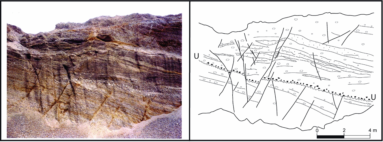
Figure 8. Normal fault system in sector 6 (see location in Fig. 9). Note that some faults are previous to the unconformity (U), while others affect the entire sedimentary series.

Figure 9. Structural data from the studied quarry: schematic plan view (position of quarry walls in June 2010) and stereoplots of bedding and fracture orientations collected along the different sectors.
Large normal faults with offsets up to 1–2 m appear at sectors 7 and 14, where they are the only deformation structures. They show N–S, NW–SE and W–E directions and cut nearly horizontal fluvial beds, without any relationship to either folds or reverse faults.
In contrast, the most conspicuous fault in sector 5 is a part of the complex ‘negative’ structure whose sedimentary infill is described in Section 4.b. It is a nearly vertical, NNW–SSE-striking fault that comprises the western boundary of a synform whose visible section is c. 10 m wide and 7 m high (Fig. 6a, b). This synform has an axis gently plunging towards the NNE (Fig. 9, stereoplot 4B) and limbs dipping up to 40º NE and 60º NW, respectively. Several high-angle, reverse, west-dipping faults splay out from the main fault surface (Fig. 6c), showing similar strike to the former (see stereoplot corresponding to sector 5 in Fig. 9). The eastern margin (sector 4 in Fig. 9) comprises a growth strata structure that evinces synsedimentary subsidence (Fig. 6d). In addition, numerous micro- and meso-scale reverse faults (showing offsets from 2 mm to 20 cm) deform both limbs of the syncline (Fig. 6e, f). Most of these are actually ductile structures (small associated propagation folds showing kink morphology) in which the continuity of the sedimentary layers has not been interrupted. Both micro-fault surfaces and axial surfaces of propagation folds mainly strike NNW–SSE close to the western boundary, whereas they show very variable orientation at the eastern boundary (see stereoplot corresponding to sector 4 in Fig. 9). Finally, a number of soft-sediment deformation structures affecting fine clastic levels (Fig. 6g) appear within this structure, suggesting the occurrence of liquefaction processes. Considering their sedimentary and deformational framework, these could be triggered by either sudden karst collapse or tectonic faulting events.
Other example of negative structure bounded by reverse-limb monoclines (‘vault’ morphology) is located at sector 9 (Fig. 10a). It appears as a narrow (3.5 m) box-shaped syncline deforming unit 2, with oblique limbs that converge and apparently close the structure to the west.

Figure 10. (a) Metre-scale collapse structure with vault morphology in sector 8 (see Fig. 9). (b) Oblique section of a metre-scale tubular structure in sector 7.
The rest of the ductile deformation structures observed in the quarry are linked to limbs of two prominent bodies (of Miocene marls and gypsums) cropping out at sectors 2 and 13–14. They constitute the cores of positive structures in which the Quaternary cover has been partially pierced. The visible thickness of the alluvial deposits drastically diminishes from c. 30 m to less than 2 m at the crest. At contacts between Miocene and Pleistocene materials, proofs of differential vertical movement, such as sharp monoclines, intrusive boundaries and gravel–marl melanges, are found. The western visible limb of the structure cropping out at sector 2 shows a dominant NNW–SSE strike, that is, parallel to the prevailing faults. The emplacement of such bodies has induced internal deformation in gravels and sands at distances of up to several tens of metres from their boundaries. Typical deformation structures are reverse kink-bands affecting gravel and sand beds (showing only a moderately angular geometry due to the coarse grain of sediments). Conspicuous examples are found at sector 2, close to the above mentioned western limb (Fig. 11). The amplitude of each individual fold is usually of decimetre scale and the strike of axial planes is also NNW–SSE. Although the majority of kink-bands dip towards the marl-and-gypsum body, conjugate west-dipping kink-bands also appear. During the last stage of this study, mining works within the quarry revealed two new minor intrusive structures in sector 13. Both produce conspicuous deformation of Pleistocene sands and gravels, although one of them does not show Miocene materials cropping out at its core.

Figure 11. High-angle reverse faults and kink bands deforming gravel and sand beds close to the diapir cropping out in sector 2 (see Fig. 9).
Finally, tubular and funnel structures disrupt the Pleistocene sediments, cutting them either vertically or obliquely (Fig. 10b). These are also filled with Pleistocene gravel and sand beds, frequently accommodated in the walls of the structure (pebbles close to the walls have their major A-axes vertical or nearly vertical). The rest of the infill is either unstructured or shows interbedded gravels and sands.
5.b. Genetic interpretation of deformation structures
Frequently, discriminating the genesis of deformation structures in Pleistocene deposits of the central Ebro Basin is not an easy task. In the past, there was a tendency to attribute every anomaly to the effect of the underlying Miocene evaporites, without proposing any explicit deformation mechanism. Indeed, suballuvial dissolution of gypsum and other evaporitic deposits induces strong deformation of the Pleistocene cover, giving rise to deformational contacts and strong local thickening of alluvial deposits (Benito et al. Reference Benito, Pérez-González, Gutiérrez and Machado1998). Further, diapiric processes (either halokinesis of evaporites, or plastic flow of water-saturated lutites as occurs in mud diapirism defined by Morgan, Coleman & Gagliano, Reference Morgan, Coleman, Gagliano, Braunstein and O’Brien1968) generate dome or antiform structures with their core frequently pierced by the intrusive materials (Simón & Soriano, Reference Simón and Soriano1986; Benito & Casas, Reference Benito and Casas1987). Nevertheless, many other structures should be related to regional tectonic deformation, that is, to regional stress fields linked to the prevailing geodynamic mechanisms at the NE Iberian plate during Neogene–Quaternary times: (i) Europe–Iberia–Africa convergence; (ii) rifting at the Valencia trough; and (iii) residual and topographical body forces at the Pyrenean Orogen (Liesa & Simón, Reference Liesa and Simón2009). Stress systems resulting from such tectonic settings are mostly extensional (vertical σ1 axis), with nearly horizontal E–W to ENE–WSW σ3 axis (Simón, Reference Simón1989; Andeweg et al. Reference Andeweg, De Vicente, Cloething, Giner and Muñoz-Martín1999; Herraiz et al. Reference Herraiz, de Vicente, Lindo-Ñaupari, Giner, Simón, González-Casado, Vadillo, Rodríguez-Pascua, Cicuéndez, Casas, Cabañas, Rincón, Cortés, Ramírez and Lucini2000).
In the studied quarry many normal faults and fractures comprise conjugate systems with persistent N–S to NNW–SSE strikes that are fully compatible with the regional stress field. Most large normal faults, although not comprising visible conjugate systems, are also oriented close to N–S. On the basis of these features we interpret a tectonic origin for these faults.
The positive structures showing a Miocene core that pierces the Pleistocene cover are interpreted as diapirs. Such deformation structures, developed at the metre to decametre scale, are common within fluvial and alluvial deposits all over the central Ebro Basin (Rioja, south Navarra and Zaragoza sectors). Diapir growth has mainly induced contractive internal deformation in the Pleistocene unconsolidated gravels and sands, up to 15–20 m from their boundaries. Combined rising and wedging effects related to the intrusion involve horizontal shortening that produces typical high-angle reverse faults and contractional kink-bands with pebbles rotated and frequently striated (Simón & Soriano, Reference Simón and Soriano1986; Benito & Casas, Reference Benito and Casas1987).
The tubular, funnel and vault structures that disrupt the Pleistocene detrital deposits are interpreted as being related to karst processes at depth. Funnel structures represent the uppermost expression of subsidence. Tubes are intra-alluvial conducts connecting surficial collapses with cavities in the underlying Miocene evaporites. Vault structures are mostly related to upwards propagation of cavities in cohesive materials. Such propagation is due to the development of successive downwards-concave tensile fractures controlled by the lithostatic stress trajectories (‘tension dome’) above the cave (Ford & Williams, Reference Ford and Williams1989).
The negative structure outcropping at sectors 4–5 described in Section 4.b also has some features of karstic subsidence structures, that is, curved rupture surfaces and significant ductile deformation. In our opinion, this structure could constitute the most conspicuous and expressive example. Nevertheless, this has clear tectonic control since a nearly vertical N–S-oriented fault forms its western boundary. Unfortunately, outcrop conditions did not allow us to assess whether the 3D geometry corresponds to either a cylindrical or an elongated N–S-trending sinking body. For this reason, a geophysical survey was achieved in order to discern its tectonic or karstic origin.
The characteristics of this deformation structure probably evince a rheological behaviour of the alluvial cover which can be described as between cohesive and non-cohesive. In the former, alluvium is dragged down into pipes opened in the underlying evaporites. The sinking material behaves as a fluid, losing its original texture and filling voids in the subsoil. The process resembles the operation of a sandglass. In the latter case, cavities developed in the soluble substratum are maintained wide for some time, but tensile failure and disengagement of successive concentric slabs from the ceiling finally result in sudden collapse of the clastic cover. The sinking body, although possibly broken into blocks, tends to maintain its internal texture and is separated from the non-deformed beds by brittle, frequently open vault-shaped fractures (Soriano & Simón, Reference Soriano and Simón1995).
The detrital deposits in the synform have maintained their integrity (layers are continuous from one limb to the other one), and most ‘reverse’ structures are not brittle cracks but reverse kink-bands or sharp monoclines. These involve net horizontal shortening of the sinking layers, which does not occur in the case of collapsed vault-shaped structures. A simple kinematical model (Fig. 12) describes the evolution of the synform. Consider a non-cohesive alluvial cover (I) in which a funnel-shaped body, bounded by non-disrupted material, flows into a karstic tube losing its internal structure according to the ‘sandglass’ model (II). Then suppose that new sedimentary material with some degree of cohesion fills the surficial depression (III), before undergoing renewed subsidence as the underlying material is removed (IV). This latter process can follow three different evolutionary models depending on the material behaviour as follows.

Figure 12. Kinematical model that explains horizontal shortening in karst subsidence structures. See detailed explanation in text.
-
(IVa) Differential subsidence of mid-cohesive material, giving rise to gentle passive bending that accommodates length variation without inducing any ‘space problem’ (sagging, according to the classification proposed by Gutiérrez, Guerrero & Lucha, Reference Gutiérrez, Guerrero and Lucha2008). Normal faults could also appear where bending involves extra layer-parallel stretching.
-
(IVb) Sudden collapse of subsoil cavities in a highly cohesive rigid cover, progressing from vault-shaped tensile cracks.
-
(IVc) Non-differential subsidence of moderately cohesive material that shows low external cohesion with respect to the bounding stable material. Shortening from the original length L 0 to the new length L 1 is accommodated by contractional structures (reverse faults or reverse kink-bands). These are mainly concentrated near the boundaries, although they can propagate inwards depending on the ability of the sinking body to transfer stress.
6. Geophysical study
Taking into account that the quarry walls essentially provide 2D observations, a geophysical survey has been carried out in order to investigate the 3D geometry of some structures.
Concerning the magnetic survey, the susceptibility values range from 0.05×10⁻⁴ to 0.8×10⁻⁴ SI for marl, and from 0.1×10⁻⁵ to 0.7×10⁻⁵ SI for sand and gravel. A priori, these values show enough contrast to define the main observed structures (collapses mainly filled with sand and some gravel, and diapirs constituted by Miocene gypsum and marl). The objective was to establish or discard the continuity of deformation structures in areas where they do not crop out. However, the results (after correction for the magnetic drift) were uniform, with variations of less than 10 nT. Gradient values are also uniform and range from 2.2 to –2 nT m−1 (Fig. 13a). Moderate differences are found between the quarry floor (low values at the central-eastern sector) and the natural landscape (medium values at the northern, western and southern surrounding sectors) due to the absence/presence of natural soil. The highest values along the borders of the surveyed area are due to the presence of agricultural soils or quarry stocks. In any case, the sharp localized anomalies detected at the southwestern sector of the quarry (D in Fig. 13a) coincide with a small diapiric structure cropping out on the quarry walls (D in Fig. 3a), confirming that this structure has no lateral continuity.

Figure 13. Most representative results of the geophysical survey (see location of the studied areas in Fig. 1c). (a) Geomagnetic survey (gradient map) of the quarry and its neighbouring area; D: diapir. (b, c) Electromagnetic survey of a selected zone of the quarry floor depicted in (a); apparent conductivity anomalies at high (63,025 Hz) and low (18,325 Hz) frequencies, respectively; RS: rim syncline. (d) GPR section along the berm of the northern quarry wall (sectors 4 and 5 in Fig. 9). (e) Panoramic field view of the above mentioned sector, to be compared with the GPR section.
The electromagnetic (EM) survey reveals the existence of a low conductivity strip at both high and low frequencies (Fig. 13b, c), which reflects the behaviour of shallow and deep materials, respectively. The curved morphology of this strip and its position, coincident with the synform located close to the eastern diapir, suggest that it could represent a segment of the rim syncline (RS in Fig. 13b, c) associated with this diapir, which was therefore active during sedimentation. The large thickness of Quaternary materials is the reason for the low conductivity of this zone.
Ground-penetrating radar (GPR) profiles acquired from the quarry floor allow us to infer variations in depth of the Miocene bedrock and the presence of conjugate faults. In addition, the GPR profiles acquired to characterize the main collapse structure gave excellent results. The profile made with the 100 MHz antenna on a berm located over this structure produced a high-resolution image (Fig. 13d) in which the U-shaped fill shown in Figure 6a is easily recognizable. Comparing this profile with other profiles acquired from the quarry floor close to the toe of the same wall, the lateral continuity of this U-shaped geometry could not be evidenced; this supports the interpretation of this structure as a karst collapse.
The diapirs of the western sector were also surveyed; however, not enough accurate results were obtained. The reasons for this are probably the irregular topography of the zone where the profile was made and the diffuse contact between Pleistocene and Miocene materials (with numerous enclaves of plastically deformed gravels included in marls).
7. Discussion
After describing and analysing the distinct deformation structures in the studied quarry, two main issues merit discussion and synthesis in order to determine the consequences of synsedimentary deformation in terrigenous sediments: (i) diagnostic criteria that can be used for distinguishing genetic types and their kinematical models; and (ii) interaction mechanisms between different deformation and deposition processes.
7.a. Diagnostic criteria for distinguishing genetic deformation types
Diagnostic criteria should initially be based on geometrical and kinematical analysis of deformation structures. First, 3D geometric features at the surface and the subsoil (the latter supported by results of geophysical survey) can constrain our genetic hypotheses: planar rupture boundaries and elongated geophysical anomalies will generally be attributed to tectonic faults, whereas nearly rounded, either positive or negative structures, will be interpreted as diapirs or karst collapses, respectively. Constraints are less narrow when only 2D exposures are available; in such situations, the kinematical approach becomes critical. In most cases, kinematical analysis will easily provide a consistent interpretation of the relative motions at the boundaries of such structures, both in the vertical (upwards v. downwards moving domains) and the horizontal axes (contractional v. extensional deformation). Nevertheless, such attributes are not exclusive to each genetic type so the kinematical analysis of structures does not properly discern their origin.
Considering the relative vertical movements, their kinematical patterns do not allow tectonic faults from diapirs or karst collapses to be distinguished in the absence of complete 3D geometric reconstructions. Moreover, distinguishing diapirs from palaeodolines can be difficult (except in the case of isolated rock bodies that have clearly risen or sunk with respect to a predeformational, recognizable marker).
Evidence of widespread horizontal extension accommodated by normal faults should generally be attributed to regional tectonics, once the dynamical consistence of the dominant fault systems with the regional stress field has been tested. In our case, such consistence is perfectly accomplished for normal faults striking close to NNW–SSE (approximate regional trend of SHmax). Nevertheless, the transition to NNE–SSW-trending σ2 trajectories, as well as local switching to orthogonal ENE–WSW- or ESE–WNW-trending trajectories, is also common (Simón, Reference Simón1989; Cortés et al. Reference Cortés, Liesa, Simón, Casas, Maestro and Arlegui1996; Simón et al. Reference Simón, Arlegui, Liesa and Maestro1999; Simón, Arlegui & Liesa, Reference Simón, Arlegui and Liesa2008). In contrast, stretching occurring on diapir crests and doline boundaries is a local process clearly controlled by the rising or the sinking domain, so does not give rise to penetrative and systematic faults and fractures. In any case, the possibility of identifying such local fault patterns depends on the availability of an adequate map view of structures.
Horizontal contraction could be caused by regional compressional tectonics, but the tectonic extensional setting of the Ebro Basin during Quaternary time leads us to rule out such a hypothesis. Local contractional structures could also be induced by piercing diapirs and, under some conditions, by karst collapses. Concerning the horizontal length balance, there is an essential difference between a tectonic normal fault and a local vertical displacement produced by diapiric intrusion or karst collapse: a normal fault accommodates horizontal extension externally imposed by the geodynamic framework, while a diapir or a collapse evolves without intrinsic far-field shortening or stretching. The possibility that either contractional or extensional structures were associated with diapirs or karst collapses therefore depends exclusively on their own kinematical mechanisms.
Both diapirism and karst subsidence essentially consist of vertical migration of material that occupies a volume formerly occupied by another material. In both types of structures, vertical displacement of rock bodies showing heterogeneous rheology frequently induces ‘space problems’, that is, a misfit of displacement trajectories that results in local, usually radial shortening or stretching. Nevertheless, the difference between the processes remain: (i) in karst subsidence, material sinks to occupy a void left by previously dissolved or dragged rocks, therefore space problems should not necessarily occur; or (ii) the core of a diapir intrudes into a rock body where no previous space is available, producing a wedge effect that tends to move the host rock away; contractional deformation is therefore intrinsic to the process. This notion was emphasized by Simón & Soriano (Reference Simón and Soriano1986) and Soriano & Simón (Reference Soriano and Simón1995), who suggested that actual reverse rupture surfaces are characteristic of diapirs whereas ‘pseudo-reverse’ contacts associated with collapse structures are in fact vault-shaped tensile cracks produced by the sudden falling of rigid blocks into an open void. Nevertheless, our detailed study of the complex U-shaped structure described in Section 4.b demonstrates that true contractional structures can also develop at the margins of a doline under the conditions stated in Section 5.b and Figure 12.
In summary, structural analysis shows that both extensional and contractional structures can be associated with each of the three analysed deformation processes. Extensional contacts may represent either tectonic faults, fractures developed at diapir crests or funnel-shaped sinkhole boundaries. Contractional contacts might arise from compressional tectonic stress fields (which is not the case in the Ebro Basin), but also from lateral compression induced by wedge action of piercing diapirs or karst subsidence of a sedimentary body with high internal cohesion but low external cohesion with respect to the bounding rock.
7.b. Interaction between different deformation and deposition processes
Further difficulty for the genetic diagnosis of deformational structures arises as different genetic processes (tectonic fracturing, karst subsidence, diapiric intrusion) frequently interact. Our detailed analysis allows us to approach the mechanisms whereby one of them triggers or influences the other. Further, the sedimentological study demonstrates that coeval deformation modifies the sedimentary environment configuration, especially in controlling the accommodation space.
An example of interaction between tectonic faulting, karst subsidence and sedimentary processes is represented by the conspicuous U-shaped structure. Although the final structure has been characterized as a palaeodoline, it is bounded by tectonic faults that could produce a fraction of the total subsidence and controlled the location of the karst sink centre (by creating discontinuities that favoured water infiltration and modifying the mechanical properties of the Quaternary cover). The resulting hole provided physical space for fluvial and aeolian sediments to be accumulated and preserved from subsequent fluvial erosion, as occurs in similar cases described by Luzón et al. (Reference Luzón, Pérez, Soriano and Pocoví2008, Reference Luzón, Rodríguez-López, Pérez, Soriano, Gil and Pocoví2012).
From the observations made, the complete evolution of this complex structure can be reconstructed; it essentially involves earlier synsedimentary movement on the eastern limb, then on the western limb. Westwards expansion of the central sand body, then cut by the western fault, constitutes the critical evidence for such a deformation sequence. The evolutionary stages can be described in detail (Fig. 14) as follows.

Figure 14. Evolutionary model of the U-shaped structure cropping out in sectors 4–5, representative of the interaction between tectonic faulting, karst subsidence and sedimentation in Pleistocene deposits of the central Ebro basin. See detailed explanation in the text.
-
1. During Early Pleistocene clastic sedimentation in a fluvial braided environment occured above Miocene evaporites. Both stratigraphical units were cut by a fault zone that triggered karst dissolution at depth.
-
2. Faulting and dissolution caused subsidence at the eastern boundary of the structure. Continuous sinking generated thickening of gravel bodies that produced a growth strata structure. Subsequent bending induced fracture propagation upwards.
-
3. The created hole acted as a sedimentary trap, in which small sand dunes accumulated constructing a sand body that expanded westwards. Episodically, subsidence induced relative rising of the water table, favouring lutite adhesion onto a damp surface. In a context dominated by high-energy and laterally migrating channels, such local subsidence prevented the fine-grained sediments from be eroded. Soft-sediment deformation structures in the lutite levels (Fig. 6g) were probably related to sudden sinking episodes.
-
4. Movement at the eastern limb vanished while the uppermost sands were deposited. Most deformation was transferred to the western limb, where a tectonic N–S-trending fault appeared, then favoured renewed karstic subsidence. The depocentre, then filled with palustrine lutites, moved to the west with respect to the previous stage.
-
5. Subsidence finished and new braided fluvial gravels were deposited over the whole deformed zone.
In the described evolutionary model the accommodation space and the accumulation of aeolian sands coincide, as well as at other sites formerly studied in the Ebro Basin (Luzón et al. Reference Luzón, Rodríguez-López, Pérez, Soriano, Gil and Pocoví2012; Gil et al. Reference Gil, Luzón, Soriano, Casado, Pérez, Yuste, Pueyo and Pocoví2013a ). However, this is not common (Kocurek & Havholm, Reference Kocurek, Havholm, Weimer and Posamentier1993; Tirsgaard & Øxnevad, Reference Tirsgaard and Øxnevad1998). Aeolian sand is only preserved from erosion during subsequent flooding episodes if it is deposited below the baseline of erosion, which is determined by subsidence and the groundwater table (Clemmensen & Dam, Reference Clemmensen and Dam1973; Fryberger & Schenk, Reference Fryberger and Schenk1988; Kocurek & Havholm, Reference Kocurek, Havholm, Weimer and Posamentier1993; Sweet, Reference Sweet1999; Mountney & Russell, Reference Mountney and Russell2009). In a tectonically stable setting a rising or falling groundwater table will have an impact on aeolian sediment preservation (Clemmensen & Dam, Reference Clemmensen and Dam1973). In contrast, base level fluctuations are not only climatically driven in some scenarios; active subsidence can play an important role in aeolian preservation (Rodríguez-López et al. Reference Rodríguez-López, Meléndez, De Boer and Soria2008). In the study case, and taking into account that large aeolian dune foresets have been preserved, a relatively rapid subsidence should be invoked which could not be accomplished just by sediment compaction. Preservation of aeolian deposits was clearly favoured by karst and tectonic subsidence, which in turn generated the necessary increase in accommodation space.
Diapirism also seems to have been partially controlled by tectonic faulting. Where vertical displacements produced by tectonic faults trigger diapirs, these are expected to show overall elongation and planar intrusive boundaries parallel to faults. This setting has been recognized in: (i) the elongated geometry of the eastern diapir (sectors 1 and 2), whose western limb crops out as a NNW–SSE-trending monocline along the quarry front; and (ii) the predominance of rupture surfaces, high-angle reverse faults and kink-bands showing the same N–S- to NNW–SSE-strike as normal faults. Such control could be substantiated by differences of lithostatic load induced by normal faults, which triggered migration of plastic Miocene materials (e.g. Pflug, Reference Pflug1973; Simón & Soriano, Reference Simón and Soriano1986; Vendeville & Jackson, Reference Vendeville and Jackson1992; Jackson, Vendeville & Schultz-Ela, Reference Jackson, Vendeville and Schultz-Ela1994).
No evidence about the interaction between diapiric and karst processes has been found in the studied area. The mechanism proposed by Benito & Casas (Reference Benito and Casas1987) to explain the occurrence of diapirs in terrace fluvial deposits thickened by karst subsidence (gravitational instability due to rapid loading and excess of fluid pressure) seems not to have operated in the studied case, since the thickness of the sedimentary cover overlying diapirs is low. In addition, the presence of uplifted, intruding evaporite bodies should not be invoked as a control for karst dissolution: this is a widespread phenomenon in the central Ebro Basin because the occurrence of evaporites at the shallow subsoil is pervasive throughout the region.
8. Conclusions
Genetic diagnosis of varied types of deformation structures in Pleistocene deposits of the central Ebro Basin has been achieved by combining structural and sedimentological analysis, as well as geophysical exploration of shallow subsoil levels.
Brittle structures of tectonic origin (essentially normal faults) are distinguished by their planar and elongated attitude as well as their preferred orientations, either determined by the remote stress field (N–S- to NNW–SSE-striking faults and fractures, roughly parallel to the regional trend of SHmax = σ2 trajectories) or modified by inherited faults (occasional E–W- to ENE–WSW-striking fractures due to local switching σ2 and σ2 stress axes).
In contrast, karst collapses and diapirs are local, broadly cylindrical structures, whose 3D geometry has been characterized by means of geophysical techniques. Diapirs and palaeodolines have been discriminated from each other where isolated rock bodies have clearly risen or sunk with respect to a predeformational recognizable marker. Where such a reference level is not available, vertical differential movements have been interpreted from kinematical analysis of internal deformation; ‘positive’ and ‘negative’ structures are not discernible, however.
Tectonic faults accommodate horizontal mainly E–W- to ENE–WSW-oriented stretching consistent with the regional extensional deformation regime. The occurrence of contractional structures does not fit such a tectonic framework. Nevertheless, these can be locally generated by: (i) lateral compression induced by wedge action of piercing diapirs; and (ii) karst subsidence of a sedimentary body with high internal cohesion and low external cohesion with respect to the bounding rock.
Interaction between different deformation and sedimentary processes did occur at the central Ebro Basin during Early Pleistocene times. Mass loss inducing local subsidence was triggered by tectonic faults (the latter acting as preferred paths for water flow, and hence dissolution or piping). Diapirism has been partially controlled by tectonic faulting, giving rise to elongated diapirs bounded by planar intrusive surfaces roughly parallel to faults.
All these deformation processes occurred while continental (fluvial, aeolian and lacustrine) sedimentation was in progress. Deformation closely controlled the accommodation space. Holes created by tectonic and karstic subsidence acted as sedimentary traps in which, in addition, the groundwater table fell. Both factors allowed sand dunes and episodic palustrine lutites to be accumulated and then preserved.
Acknowledgements
J.P. Rodríguez-López and two anonymous reviewers are thanked for their valuable comments and suggestions, which have improved the final version of the manuscript. This research has been supported by Gobierno de Aragón (project PI 030/08 and research groups Geotransfer and Análisis de cuencas sedimentarias continentales) and the project GA-LC-026/2009 (Gobierno de Aragón-Caixa). O. Pueyo is thanked for help with the geophysical study. H. Gil benefited from a grant from Gobierno de Aragón.