


1. Introduction
The permeability of fractured reservoirs, such as those used for production of groundwater, geothermal water and petroleum, depends on fluid pressure and transport in fractures (Nelson, Reference Nelson1985; Aguilera, Reference Aguilera1995; Singhal & Gupta, Reference Singhal and Gupta1999; S. L. Brenner, unpub. Ph.D. thesis, Univ. Bergen, 2003). It has been proposed that high fluid pressures create temporary fluid-flow pathways in reservoirs through hydrofractures (fluid-driven fractures) that are subsequently sealed and form mineral vein networks (Sibson, Reference Sibson and Parnell1994; Aguilera, Reference Aguilera1995; McCaffrey, Lonergan & Wilkinson, Reference McCaffrey, Lonergan and Wilkinson1999; Cosgrove, Reference Cosgrove2001; Gudmundsson, Fjeldskaar & Brenner, Reference Gudmundsson, Fjeldskaar and Brenner2002; S. L. Brenner, unpub. Ph.D. thesis, Univ. Bergen, 2003). The fluid overpressure (net pressure or driving pressure) of hydrofractures is commonly defined as the fluid pressure exceeding the stress normal to the fracture, which for extension fractures (mode I cracks) is the minimum principal compressive stress (maximum principal tensile stress) σ3 (cf. Gudmundsson, Fjeldskaar & Brenner, Reference Gudmundsson, Fjeldskaar and Brenner2002).
Mineral veins, being palaeohydrofractures, give information about past fluid transport and flow networks (cf. S. L. Brenner, unpub. Ph.D. thesis, Univ. Bergen, 2003). The study of mineral veins is thus important for understanding fluid and mineral transport in rocks and reservoirs. The mechanism for the formation of gypsum veins, however, is still a matter of debate. Proposed mechanisms include mineral precipitation in near-surface open fractures (Gustavson, Hovorka & Dutton, Reference Gustavson, Hovorka and Dutton1994; El Tabakh, Schreiber & Warren, Reference El Tabakh, Schreiber and Warren1998), formation due to crystallization pressure (Taber, Reference Taber1918; Halferdal, Reference Halferdal1960) and hydraulic overpressure (Shearman et al. Reference Shearman, Mossop, Dunsmore and Martin1972).
Herein, I present a hydrofracture-based model for the formation of gypsum veins in red mudstones of the Upper Triassic Mercia Mudstone Group near the village of Watchet on the Somerset Coast of SW England. I propose that the gypsum veins formed as hydrofractures related to fluid transport along faults into the host rocks and the stress concentration associated with the transformation of nodular anhydrite to gypsum.
In the first part of this paper, field measurements of mineral veins and faults in a 300 m cliff section (Figs 1, 2) are presented. I provide evidence of fluid transport along these faults and determine the orientation of the minimum principal compressive stress at the time of vein formation from the orientation and the thickness/dip relationship of gypsum veins. Cross-cutting relationships, as well as mineral fibre geometries, are used to obtain the displacement mode of the veins. In the second part of this paper I discuss the proposed formation mechanism of the gypsum veins in detail.

Figure 1. Simplified geological map of the study area and its surroundings. The village of Watchet, at the Somerset Coast, SW England, is located in the southeastern part of the Bristol Channel Basin. Modified from Peacock & Sanderson (Reference Peacock and Sanderson1999).

Figure 2. Part of the 300 m long outcrop on the Somerset Coast west of Watchet Harbour, SW England. The cliffs consist of red mudstones of the Upper Triassic Mercia Mudstone Group with white layers of nodular gypsum. Some layers contain dense anastomosing networks of satin spar (fibrous gypsum) veins. The section is dissected by many faults (indicated); gypsum veins follow the fault planes. View toward south; person for scale.
2. Geological background
The Bristol Channel Basin (Fig. 1) is one of a series of roughly E–W-trending Mesozoic intracratonic extensional sedimentary basins in southern England. Along with adjacent areas, these basins result from Permo-Triassic N–S extension during the break-up of Pangaea (Van Hoorn, Reference van Hoorn1987; Coward, Reference Coward and Boldy1995).
Coastal cliffs near the village of Watchet on the Somerset Coast, the south coast of the Bristol Channel Basin (Fig. 1), are largely comprised of the Upper Triassic ‘Mercia Mudstone Group’ (Whittaker & Green, Reference Whittaker and Green1983). The Mercia Mudstone Group in this region is up to 484 m thick and has a low regional dip to the SW, but with local small-scale basins and domes (Whittaker & Green, Reference Whittaker and Green1983). Often referred to by its former name, the ‘Keuper Red Marls’, the lower Mercia Mudstone Group is only slightly calcareous, and uniform over wide areas (Bennison & Wright, Reference Bennison and Wright1969). The lower Mercia Mudstone Group consists of several tens of metres of largely unfossiliferous, poorly bedded, red or reddish-brown mudstones and siltstones which can be correlated chrono- or lithostratigraphically only on a local scale (Whittaker & Green, Reference Whittaker and Green1983; Leslie, Spiro & Tucker, Reference Leslie, Spiro and Tucker1993). In the upper part of the red mudstones there are laterally impersistent (non-continuous) evaporite-rich horizons, mainly composed of white nodular gypsum. Many of these horizons are associated with grey-green beds (Whittaker & Green, Reference Whittaker and Green1983). Poorly cemented sand pockets, with diameters of a few metres, and subvertical sand dykes occur in the red mudstones (Cosgrove, Reference Cosgrove2001). Towards higher stratigraphies, green, calcareous or dolomitic siltstone beds of decimetre thicknesses gradually become more common (Whittaker & Green, Reference Whittaker and Green1983; Leslie, Spiro & Tucker, Reference Leslie, Spiro and Tucker1993).
The Mercia Mudstone Group is commonly interpreted as being deposited under playa lake or desert plain conditions (Bennison & Wright, Reference Bennison and Wright1969; Simms & Ruffell, Reference Simms and Ruffell1990), in which case the green layers represent sabkha conditions (Whittaker & Green, Reference Whittaker and Green1983). Nodular gypsum may have formed primarily as surficial crusts in ephemeral pools or disseminated within the sediment and then been remobilized to nodules (Leslie, Spiro & Tucker, Reference Leslie, Spiro and Tucker1993). The evaporite horizons have been interpreted as marine transgressions (Whittaker & Green, Reference Whittaker and Green1983; Ziegler, Reference Ziegler1990), or as having been formed during drying up of the basin, following periods of basin extension (Cosgrove, Reference Cosgrove2001).
The tectonic evolution of the Bristol Channel Basin is complex. During the Late Jurassic to Early Cretaceous N–S extension, major fault systems were active along the basin margins (Kamerling, Reference Kamerling1979; Van Hoorn, Reference van Hoorn1987). Then, roughly E–W-striking normal faults developed throws from metres to a few tens of metres (Whittaker & Green, Reference Whittaker and Green1983). Sedimentary dykes in the Mercia Mudstone Group formed as vertical hydrofractures (Cosgrove, Reference Cosgrove2001). During the Late Cretaceous and Early Tertiary N–S contraction associated with Alpine tectonics, the basin was inverted and many older structures were reactivated (Dart, McClay & Hollings, Reference Dart, McClay, Hollings, Buchanan and Buchanan1995; Nemcok, Gayer & Miliorozos, Reference Nemcok, Gayer, Miliorozos, Buchanan and Buchanan1995).
3. Mineral veins at Watchet
3.a. General description
Red mudstones of the lower Mercia Mudstone Group are exposed north of the village of Watchet (Figs 1, 2). I studied faults and mineral veins in a 300 m long section of 10–15 m high cliffs west of Watchet Harbour (Fig. 2). Whereas the cliffs provide excellent outcrops, the beach itself does not provide any outcrops. Beds dip a few degrees to the SW. Large parts of the section consist of relatively massive red mudstones, where hardly any bedding planes or other sedimentary structures are visible. In some parts of the section, nodular gypsum layers and/or grey-green carbonatic siltstone layers indicate bedding.
There are few marker horizons. Some grey silty horizons can be used for short distances but normally cannot be followed over long distances. Nodular gypsum layers can be used for short-distance correlation, but they are usually very irregular. Due to the lack of extensive marker horizons, the fault throws are often difficult to determine.
In the middle part of the section, layer thickness is on the decimetre scale. There are many centimetre-thick nodular gypsum layers with few veins, some rather massive gypsum layers and some with grey-green siltstone layers. At the west and east ends of the section, there are several-metre-thick mudstone layers with dense anastomosing networks of fibrous gypsum (satin spar) veins. These vein systems are confined to parts of the mudstone. The top of the mudstone layer hosting the networks is commonly marked by a grey siltstone layer which arrests the veins. This grey layer does not occur everywhere at the tops of the networks and is difficult to follow along the outcrop. There are also some nodules above the top parts of the vein networks.
3.b. Fault data
Some 28 faults dissect the studied section. There are gypsum veins along 24 fault planes; four fault planes, however, are open, that is, not filled with gypsum. I measured the strike, dip and throws of all faults along a 300 m long E–W scan line parallel to the coast. The type of fault (e.g. normal, reverse) and the absence or presence of gypsum veins was also recorded for each fault (Fig. 3). There is a clear dominance of WNW-trending, that is, basin margin-parallel, faults. There are 23 normal fault planes, 19 of which contain 2–90 mm thick gypsum veins. The displacements on these normal faults are mainly in the order of centimetres to decimetres, but in the western part of the profile, fault throws reach several metres. There are also four reverse faults with displacements of several metres, which probably are inverted normal faults. Their planes are injected with up to 210 mm thick gypsum veins. Most of the reverse faults are at the eastern end of the profile. For one fault the sense of displacement could not be determined. In the profile there is also a 3 cm thick subvertical sand dyke; a vein follows the dyke.
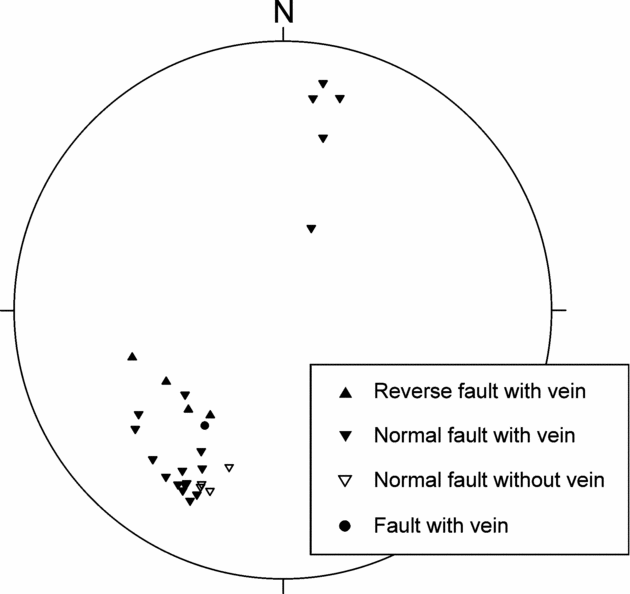
Figure 3. Stereoplot of 28 faults dissecting the 300 m long profile near Watchet (cf. Figs 1 and 2). The plot is an equal area, lower hemisphere, conventional plot of the projection of poles to fault planes. Twenty-four faults (filled symbols) have veins along their planes, whereas no veins occur along the planes of four normal faults (open triangles). The displacement of one fault is unclear (filled circle), the other faults are normal (24) or reverse (4). The faults trend predominantly WNW and mostly dip 50–70°N.
Along 24 of the 28 fault planes, there are gypsum veins. The crystal fibres of many veins are not identifiable. On some fault planes, however, there are crystal vein fibres. Some fibres are subvertical, but most are sub-perpendicular to the vein walls. Along one reverse fault plane (Fig. 4), there runs a vein all the way to the uppermost exposed part of the fault. In the host rock, most veins stop at the same grey layer on both sides of the fault, but in this case the vein follows the fault to a shallower level than the grey layer.

Figure 4. Reverse fault in the profile at Watchet (Figs 1–3). There is a network of white gypsum veins on either side of the fault plane. The network stops abruptly at a grey siltstone layer (indicated) and is absent from the overlying mudstones. A gypsum vein follows parallel to the fault plane to a level above the vein network. View toward southeast; person for scale.
3.c. Vein data
In the eastern part of the profile, I measured the orientations and thicknesses of 160 gypsum veins in a dense vein network located in a thick mudstone layer. The thickness measurements have an accuracy of ±0.5 mm and were made perpendicular to the vein walls. Figure 5 shows the strike and dip of 160 gypsum veins measured away from the faults. There is no clear predominant attitude. Vein dips vary from horizontal to vertical and the strikes are in all directions. NW–SE-trending and mostly NE-dipping veins, however, are somewhat more common.

Figure 5. Stereoplot of 160 gypsum veins from the dense anastomosing vein network at the east end of the profile in Figure 3 at Watchet. This equal area, lower hemisphere, conventional plot of the projection of poles to the vein planes shows a slight predominance of the dip NE.
Figure 6 shows the thickness–frequency distribution of the 160 measured veins. The thickest vein is a 28 mm thick subhorizontal vein which can be traced for many tens of metres and cuts through all the other veins along its trace. This thick vein is thus among the youngest. The thickness distribution is skewed to the right, meaning there are more thin than thick veins. Most vein thicknesses fall within the class 3–4 mm. Frequency distributions of vein thicknesses are commonly reported to follow power-laws (Vermilye & Scholz, Reference Vermilye and Scholz1995; Gudmundsson, Fjeldskaar & Brenner, Reference Gudmundsson, Fjeldskaar and Brenner2002), but the present thickness distribution is best approximated by a log-normal law (cf. Stowell, Watson & Hudson, Reference Stowell, Watson, Hudson, McCaffrey, Lonergan and Wilkinson1999). Because very thin veins are presumably not seen, and because thicknesses less than 0.1 mm could not be measured, the real proportion of thin veins may be greater.

Figure 6. Thickness frequency distribution of the 160 measured gypsum veins from Watchet (cf. Fig. 5). Class widths are 1 mm, and the central value of every second class is given. Values coinciding with class margins are counted to the left (given to the lower class). Most veins are thinner than 5 mm; the thickest vein is 28 mm. The frequency distribution is best approximated by a log-normal law.
Cross-cutting relationships were investigated in a dense network of gypsum veins at the eastern end of the profile (Fig. 7). In many apparent cross-cuts, the veins just meet in a curved manner (Fig. 8) and change direction under steep angles. The local stress fields of the veins interact during their formation, but the exact mechanism for the formation of such curved nearby veins is not clear. Each apparent cross-cutting relationship was carefully examined, revealing a total of 97 true cross-cuttings. The results indicate no predominant age relationship between the veins (in 30 cross-cuttings, the subhorizontal vein is younger, and in 55 cross-cuttings the subvertical vein is younger), suggesting that the veins may all have formed essentially at the same time.

Figure 7. Dense network of gypsum veins at the eastern end of the outcrop at Watchet. The attitude and thickness of 160 veins were measured (Figs 5, 6). Most of the apparently horizontal veins have dips up to 30°, and there is no preferred vein orientation (cf. Figs 5, 10 and 11). Ninety-seven cross-cutting relationships indicate that most veins are extension fractures and of similar age. View toward ESE; the measuring tape (left lower corner) is 1 m long.

Figure 8. Many apparently cross-cutting veins only meet and change direction without actually crossing. View toward southeast; the visible part of the measuring tape is 18.5 cm long.
In non-layered and rather homogeneous rocks such as the red mudstones, the shear displacement can be too small to be seen with the naked eye. However, the orientation of vein fibres is an additional indicator for the main mode of displacement. Syntectonic fibres grow along the opening trajectory, so that the orientation of the gypsum fibres can be used to determine the direction of opening of the veins (Durney & Ramsay, Reference Durney, Ramsay, de Jong and Scholten1973). If the fibres are mainly normal to the fracture plane, the veins are extension fractures (mode I cracks); fibres oblique to the vein walls indicate a component of shear displacement during vein formation (mode II or III cracks), that is, a mixed-mode fracture formation. The fibrous gypsum veins grow as antitaxial veins, as is typical when the vein fill is mineralogically different from the composition of the wall rocks (van der Pluijm & Marshak, Reference van der Pluijm and Marshak2004). Antitaxial veins are thought to form by the crack-seal mechanism (Ramsay, Reference Ramsay1980), where the cracking occurs at the contacts between the fibres and the vein wall. A central parting (medial suture; Fig. 9) is a typical feature of such veins and indicates the site of the original fracture (van der Pluijm & Marshak, Reference van der Pluijm and Marshak2004).

Figure 9. The thickest vein in the eastern outcrop at Watchet is 28 mm, subhorizontal and can be traced for tens of metres. The gypsum fibres in this vein are subvertical and perpendicular to the vein walls. The dark ‘suture’ line in this vein indicates the site of the original fracture of the antitaxial mineral vein. The fibres in most inclined veins are sub-perpendicular to the vein walls, indicating that the veins are extension fractures. (a) Photograph, view toward southeast, the visible part of the measuring tape is 18 cm long. (b) Sketch of the main features of (a): the mineral veins are white, the host rock is grey. The central ‘suture’ line is indicated by a dotted line, the direction of the vein fibres by thin dashed lines.
In the subhorizontal veins, the fibres are mostly vertical, that is, perpendicular to the walls. Similarly, in the inclined veins the fibres are mostly perpendicular to the walls, indicating mode I (opening-mode) displacement (Fig. 9). Only a few inclined veins have vertical fibres, indicating shear displacement during their mixed-mode formation. The field observations thus indicate that most of the gypsum veins are extension fractures.
There is no clear correlation between vein strike and thickness (Fig. 10). By contrast, there is a clear correlation between vein dip and thickness since all the thick veins have low dips (Fig. 11). Since the veins are extension fractures, they propagated parallel to the maximum and intermediate principal compressive stresses, σ1 and σ2, respectively, and perpendicular to the minimum principal compressive (maximum principal tensile) stress, σ3. Therefore, the orientation of mineral veins (or palaeohydrofractures) can be used to estimate the orientation of the principal stresses during vein formation, assuming that they have not been deformed considerably subsequent to their formation. The thickest veins are subhorizontal. This indicates a low differential stress with a roughly horizontal orientation of σ1 and σ2, and vertical orientation of σ3, at the time of vein formation.

Figure 10. Aperture/strike relationships of 160 gypsum veins measured at Watchet. There is no clear correlation between the strike and the vein aperture. There are thin and thick veins in all strike directions.
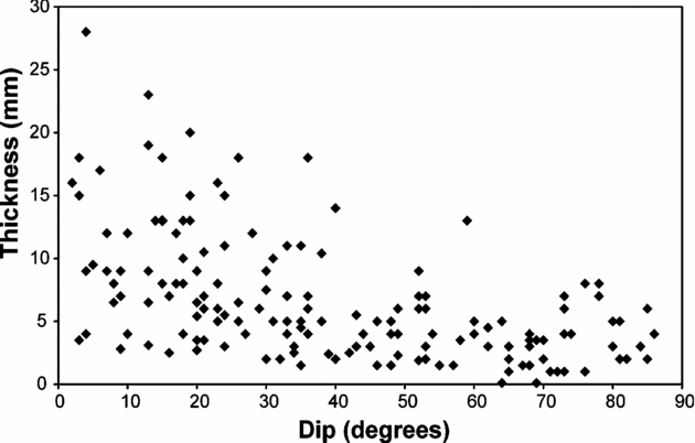
Figure 11. Aperture/dip relationships of 160 gypsum veins measured at Watchet. All the thick veins are subhorizontal, indicating that the minimum principal compressive stress was vertical at the time of vein formation.
4. Formation of the gypsum veins
Mineral veins form through several related processes: fracturing, mineral dissolution, transport and precipitation. These processes may occur simultaneously and be repeated many times to form a single mineral vein. For a vein to form there must thus be a fluid, a material source, a fracture providing space, and suitable pressure–temperature conditions for material precipitation. The proposed mechanism for vein formation at Watchet is illustrated in Figure 12 and will be discussed in detail in the following sections.

Figure 12. Schematic sketches illustrating the proposed conceptual model of gypsum vein formation at Watchet. (a′) is a close-up view of the framed part in (a), whereas (b), (c) and (d) represent succeeding steps during vein formation in the same layer. (e) illustrates vein formation in a layer at a level somewhat higher up in the stratigraphy. (a) I propose that water for the gypsum veins at Watchet was transported from deeper levels in the sedimentary basin along faults into the mudstones (light grey), where it gained access to nodular anhydrite (white). The water then dissolved the anhydrite and formed gypsum. The volume increase due to this reaction and the low permeability of the mudstones led to build-up of high fluid excess pressure (p e) in the nodules that created high tensile stress concentrations at the ends of the long axes of the nodules (σt max). (b) Eventually, hydrofractures were generated at these points. (c) The resulting hydrofractures connected the gypsum nodules and led to high fluid pressure in the next nodule and again to tensile stress concentration and hydrofracturing. (d) Finally, all nodules in one layer are transformed into gypsum and connected by gypsum veins. Additional calcium sulphate in the water was transported along the faults into higher stratigraphic levels. (e) In layers without anhydrite nodules, a dense network of veins could develop, but some hydrofractures were arrested upon encountering a siltstone layer with contrasting mechanical properties (darker grey shading).
4.a. Origin of fluids and fluid pressure
The fluids transporting the vein material could have been supplied through several processes. Much of the water in sedimentary basins is either meteoric or depositional. Fluids can also be generated from solids. Important reactions are, for example, clay dehydration such as smectite-to-illite transition, dehydration of gypsum to anhydrite and other mineral reactions (Bjørlykke, Reference Bjørlykke, Jamtveit and Yardley1997; Osborne & Swarbrick, Reference Osborne and Swarbrick1997). Also, at deep levels, metamorphic dewatering reactions may take place.
Fluid flow in sedimentary basins may be driven by compaction due to burial, or by convection. The flow can also be driven by hydraulic head, topographic elevation, osmosis, chemical potential gradients, porosity and temperature changes, and buoyancy (Neuzil, Reference Neuzil1995; Bjørlykke, Reference Bjørlykke, Jamtveit and Yardley1997; Osborne & Swarbrick, Reference Osborne and Swarbrick1997). Commonly, the fluid pressure builds up beneath or within rocks with very low permeabilities (‘impermeable seals’), and this pressure adds to that generated by processes such as disequilibrium compaction (when sediment with low permeability is buried so rapidly that fluids cannot be expelled fast enough) and tectonic compression (Bjørlykke, Reference Bjørlykke, Jamtveit and Yardley1997; Osborne & Swarbrick, Reference Osborne and Swarbrick1997). In dynamic systems, high fluid pressures can be maintained when the processes perturbing the pressure and fluid fluxes are in balance (Neuzil, Reference Neuzil1995).
During the formation of the rocks, high fluid pressure may have been developed as a result of disequilibrium compaction. However, as discussed below, the veins are not likely to have formed early in the basin history. The fluid source for the mineral veins is thus not entirely clear. Mineral reactions at deeper levels in the basin may, nevertheless, have yielded fluids.
4.b. Fluid transport along faults and into the layers
Mudstones have a very low original permeability and are commonly effective barriers to fluid transport in sedimentary basins (Cartwright, Reference Cartwright, Jamtveit and Yardley1997). Consequently, fluid transport into the mudstones is most likely to occur along fractures and faults (Fig. 12a′). Gypsum veins along almost all the fault planes at Watchet (Figs 2, 3, 4) indicate fluid transport along the faults. Some veins even follow the fault planes to depths shallower than those of the networks in the adjacent layers, where the veins commonly stop at a grey siltstone layer (Fig. 4).
Active faults commonly transport crustal fluids (Byerlee, Reference Byerlee1993; Barton, Zoback & Moos, Reference Barton, Zoback and Moos1995; Gudmundsson, Reference Gudmundsson1999, Reference Gudmundsson2000; Haneberg et al. Reference Haneberg, Mozley, Moore and Goodwin1999; Faybishenko, Witherspoon & Benson, Reference Faybishenko, Witherspoon and Benson2000). Inactive and active fault zones with associated mineral veins offer good evidence of former fluid transport along faults (Gudmundsson, Fjeldskaar & Brenner, Reference Gudmundsson, Fjeldskaar and Brenner2002; Brenner & Gudmundsson, Reference Brenner, Gudmundsson, Stephansson, Hudson and Jing2004a). Fluid transport is likely to occur along a fault each time it is active (slips). Then, fluid flow may occur upwards along the fault plane.
Veins with thicknesses of many millimetres (Figs 3, 4) must form over a long time, and fluid transport during fault slip may not be sufficient to form thick veins. However, if the fault plane is oriented favourably in the stress field, hydrofractures may also propagate along the plane when the fault is inactive (non-slipping). A hydrofracture is initiated (Gudmundsson, Reference Gudmundsson1990) when the internal fluid excess pressure, p e, defined as the pressure in excess of the lithostatic stress p l, in a fluid source reaches the local in situ tensile strength, T 0, of the host rock, typically between 0.5 and 6 MPa (Amadei & Stephansson, Reference Amadei and Stephansson1997). In higher stratigraphic levels, hydrofractures commonly develop a fluid overpressure due to buoyancy (Spence, Sharp & Turcotte, Reference Spence, Sharp and Turcotte1987; Gudmundsson, Reference Gudmundsson1990, Reference Gudmundsson1999; Rubin, Reference Rubin1995; Ray, Sheth & Mallik, Reference Ray, Sheth and Mallik2007), particularly when the fluid has a low density, such as geothermal water. Because hydrofractures commonly are extension fractures, they propagate perpendicular to the minimum principal compressive stress (maximum principal tensile stress) σ3 (cf. Gudmundsson, Fjeldskaar & Brenner, Reference Gudmundsson, Fjeldskaar and Brenner2002; Brenner & Gudmundsson, Reference Brenner, Gudmundsson, Stephansson, Hudson and Jing2004a). Propagating hydrofractures may use non-slipping faults, which still are planes of weakness, where the tensile strength is essentially zero, as a pathway for some distance. When, however, the stress field is very unfavourable for hydrofracture propagation and fluid transport along the fault plane, and more favourable for hydrofracture injection into the host rock, the latter would occur (Brenner & Gudmundsson, Reference Brenner and Gudmundsson2005).
4.c. Local material source: transformation of nodular anhydrite to gypsum
In the Mercia Mudstone Group there are many horizons of nodular gypsum (cf. Figs 2, 12a). These nodules were presumably local sources for the gypsum that formed the veins. There is some debate as to whether anhydrite may be deposited directly or if it always results from diagenesis (Billo, Reference Billo1987). Sedimentary gypsum deposits are altered during burial to anhydrite already in the shallow subsurface because of high temperatures and/or reaction with saline brines (Kasprzyk, Reference Kasprzyk1995). Murray (Reference Murray1964) states that gypsum may be the common, if not universal, original calcium sulphate mineral, and nodular anhydrite beds are a common diagenetic facies. To be a source of calcium sulphate for veins, the deposited mineral may be either primarily anhydrite or gypsum. At burial depths of many hundreds of metres, any gypsum would be transformed into anhydrite. Murray (Reference Murray1964) reports a characteristic cycle in diagenesis of gypsum–anhydrite minerals: surface or near-surface gypsum replaced by anhydrite as result of burial and in turn replaced by gypsum if anhydrite is brought back closer to the surface. This cycle is likely to have taken place in Watchet. As the rocks reach lower temperature and pressure conditions during uplift, anhydrite nodules can be hydrated to gypsum if water gets access to them.
The hydration of anhydrite to gypsum occurs according to the reaction:
where CaSO4 is anhydrite, CaSO4 · 2 H2O is gypsum, and H2O is water, meaning that water is built into the crystal lattice of the calcium sulphate. Compared with the sum of the volumes of anhydrite and water, the hydration leads to a volume decrease of about 10%. When water is added to the system, however, the transition from anhydrite to gypsum is associated with a volume increase of more than 60% (Shearman et al. Reference Shearman, Mossop, Dunsmore and Martin1972).
4.d. Formation of veins as hydrofractures
Once in the mudstones, and with access to the anhydrite nodules, the fluids start to dissolve the anhydrite. The hydration of anhydrite to gypsum and the related volume increase lead to a swelling pressure of 295 kPa (Azam, Reference Azam2007). Because the surrounding mudstones had a very low permeability, the fluids were then kept in the nodules. Hence, in these local closed systems, high fluid pressures developed (Fig. 12a).
More and more water could enter the mudstones and nodules along the faults. Because fluid flow is always in a direction from the highest to the lowest hydraulic potential (Domenico & Schwartz, Reference Domenico and Schwartz1998), the water was prevented from flowing back by additional buoyant water. Since the low permeability of the mudstone did not allow the water to penetrate the host rock, the water could not leave the nodules again. Therefore the volume increase of any transformed anhydrite to gypsum as well as additional amounts of water increased the fluid pressure in the nodules.
Overpressured elliptical nodules can be compared to fluid-filled elliptical cavities, which develop high concentrations of tensile stresses at their long-axis ends (σt max; Fig. 12a′; Savin, Reference Savin1961; Maugis, Reference Maugis2000). When these tensile stresses reach the tensile strength of the host rock, hydrofractures are initiated (cf. Section 4.b). Hydrofractures are most likely to form at the lateral tips of the nodules with high tensile stress concentrations (Fig. 12a′, b). The local stress field around an elliptical nodule thus favours horizontal hydrofracture propagation from their lateral tips (Fig. 12b). Indeed, subhorizontal veins grow out of the long axis of many nodules at Watchet (Figs 13, 14).

Figure 13. Nodular gypsum layers in mudstones at Watchet. Some layers consist of a few large white nodules in red mudstones and connected by horizontal gypsum veins (indicated). Few veins occur in the mudstones between the nodular layers. View toward south; the measuring tape is 0.5 m long.

Figure 14. Close-up view of the ends of two white gypsum nodules. At their long-axis ends, the nodules are connected through gypsum veins which formed as hydrofractures when the fluid excess pressure inside the nodules exceeded the tensile strength of the surrounding mudstone host rock. View toward SSE; the visible part of the measuring tape is 8 cm long.
These veins are subhorizontal and connect the nodules in a layer (Fig. 12c, d). Consequently, the water had access to all the nodules, and all the anhydrite is replaced by gypsum (Fig. 12d). The local stress field around an elliptical nodule favours horizontal hydrofracture propagation from the lateral tips of the nodules (Savin, Reference Savin1961; Pollard & Segall, Reference Pollard, Segall and Atkinson1987; Maugis, Reference Maugis2000). Therefore, the veins formed in the nodular layers tend to become subparallel and horizontal and do not develop a network of variously dipping veins (Fig. 12d).
Apart from these veins, there is essentially no deformation in the host rock. Thus, the nodular anhydrite was replaced isovolumetrically by gypsum and the excess calcium sulphate was transported out of the nodules into the hydrofractures and precipitated as gypsum in the space provided by the fractures when the solution was supersaturated with respect to calcium sulphate.
The field data suggest that water saturated with calcium sulphate was transported upwards along the faults and gained access to thick mudstone layers where anhydrite nodules were absent. In these thick ‘homogeneous’ layers, a dense anastomosing network of veins developed (Figs 2, 7, 12e). Here, hydrofractures were injected from the fault planes into the host rock, when the fluid overpressure of the calcium-sulphate water reached the tensile strength of the mudstone. Because the fluid overpressure in higher stratigraphic levels commonly includes a buoyancy term (see Section 4.b), this fluid overpressure p o may have been higher than the fluid excess pressure p e in the anhydrite nodules.
The differential stress was presumably very low at the time of vein formation. Consequently, since the state of stress was close to isotropic, it did not favour any particular vein orientation. No local stresses seem to have inhibited the veins to propagate in all directions inside these mudstone layers. The differential stress was presumably smaller inside the soft mudstone layers without nodules than in the layers with nodules, which had a higher stiffness (cf. Bell, Reference Bell2000). Possibly some veins used existing steep and favourably oriented shear fractures as channels. Then the fluid pressure during vein formation may have been just sufficient to open these shear fractures. That the vein fibres are also sub-perpendicular to the vein walls in the steep fractures, however, indicates that the veins formed primarily as extension fractures, that is, hydrofractures.
Mineral veins are commonly the result of many fluid injections (e.g. Fisher & Brantley, Reference Fisher and Brantley1992; Davison, Reference Davison1995; Bons, Reference Bons2000). For example, in the crack-seal mechanism (Ramsay, Reference Ramsay1980), crack-seal cycles can be repeated up to hundreds of times. During each injection, the vein thickness increment is in the order of 10–100 μm (Fisher & Brantley, Reference Fisher and Brantley1992; Fisher et al. Reference Fisher, Brantley, Everett and Dzvonik1995) or, at most, 1 mm (Gustavson, Hovorka & Dutton, Reference Gustavson, Hovorka and Dutton1994). Since each increment seals in 103 to 104 years, and the time between fracturing is 102 to 103 years, the time for the formation of an individual vein is in the order of 103 to 106 years (Fisher & Brantley, Reference Fisher and Brantley1992). In the present conceptual model for Watchet, whenever enough fluids had gained access to a nodule and the fluid pressure rose, a hydrofracture was initiated and propagated, often along earlier veins, into the host rock, and from this hydrofracture a thin vein material increment precipitated.
The fluids migrated upwards along the faults and, eventually, out of the present exposures. For normal veins, large amounts of fluids are necessary to provide the minerals. The fluid/rock ratio, that is, the amount of fluid that is needed to pass through a rock body in order to form mineral veins inside, may be as much as in the order of 103 to 104 (Fisher & Brantley, Reference Fisher and Brantley1992; Bons, Reference Bons2000). For the gypsum veins at Watchet, however, much less fluid was probably needed to produce the veins. The fluid that dissolves the anhydrite in one nodule forms a hydrofracture and precipitates gypsum in a newly opened nearby fracture, due to the lower pressure in the fracture and a strong dependency of anhydrite (and gypsum) solubility on the pressure (e.g. Blounot & Dickson, Reference Blounot and Dickson1969). The fluid then reaches the next nodule, the fluid pressure increases, new material is dissolved and precipitated in the next fracture, and so on. Thus, in Watchet the same fluid may have been reused many times before it left the system.
4.e. Time and depth of vein formation
Cross-cutting relationships of subhorizontal and subvertical gypsum veins at Watchet indicate that the veins may all have formed essentially at the same time (see Section 3.c). Since most of the gypsum veins were formed as extension fractures, the mudstone had some tensile strength at the time of vein formation, indicating that vein formation did not take place in very young soft rocks (cf. Bell, Reference Bell2000). More information on the time of vein formation is given by the field observation that a gypsum vein follows a sand dyke and gypsum veins in dense networks cross-cut the sand dykes (Cosgrove, Reference Cosgrove2001). The veins thus post-date the sand dykes, which were formed during basin extension. These observations suggest that the gypsum vein formation did not occur at a time early in the basin history.
In the proposed model, the vein formation occurs at the depth of the anhydrite–gypsum transition. The hydration of anhydrite to gypsum is driven by the solubility of anhydrite being greater than that of gypsum at low temperatures, low salinities and shallow depths (Jowett, Cathles & Davis, Reference Jowett, Cathles and Davis1993), but the exact conditions are not clear (cf. Kasprzyk, Reference Kasprzyk1995). Thermodynamic calculations indicate that the transformation occurs at temperatures below 14°C in the presence of saturated NaCl solution, and that increasing confining pressure raises this temperature (Macdonald, Reference Macdonald1953). The depth of the anhydrite–gypsum transition depends on the temperature, the fluid pressure, the lithostatic pressure and the composition of the pore fluids, particularly their salinity and the activity of the water (Macdonald, Reference Macdonald1953; Blounot & Dickson, Reference Blounot and Dickson1969; Jowett, Cathles & Davis, Reference Jowett, Cathles and Davis1993). Boehner, Adams & Giles (Reference Boehner, Adams and Giles2003) observed that Carboniferous anhydrite depositions are hydrated to gypsum down to a depth of about 400 m. According to Jowett, Cathles & Davis (Reference Jowett, Cathles and Davis1993), however, the depth of anhydrite–gypsum transformation is rarely less than 400 m, but can reach several kilometres, depending on the heat conductivity of the overlying rocks and the tectonic setting.
That the thickest veins are subhorizontal indicates a roughly horizontal orientation of σ1 and σ2, and vertical orientation of σ3, at the time of vein formation. The lack of dominant vein dip directions, however, indicates that the differential stress was small during vein formation. The poorly bedded nature of the mudstone alone cannot explain the formation of such an anastomosing network of veins. A vertical orientation of σ3, but with a magnitude close to σ1, is a stress condition that occurred during the uplift of the Bristol Channel Basin, when the basin was inverted, which would imply vein formation during the Alpine basin inversion. Cosgrove (Reference Cosgrove2001) also suggests that the increase in fluid pressure responsible for the formation of the gypsum veins in the Mercia Mudstone Group was mainly due to tectonic compression during basin inversion. This would imply that the gypsum veins formed rather late in the basin history.
4.f. Restriction of gypsum veins to certain layers
In Watchet, the mineral veins are confined to some of the mudstone layers. The veins in the nodular layers normally connect only the individual nodules and are not present in the mudstones above and below (Figs 13, 14). Also, the dense networks of veins often end abruptly. In some parts of the outcrop, there is a grey siltstone layer that stops most of the veins (Figs 4, 12e); only a few veins go through this layer to shallower layers. This grey layer is 10–20 cm thick with a few small nodules and is somewhat calcareous. In some parts of the section there are two grey layers close together that stop the gypsum veins. Some relatively massive evaporite layers also acted as barriers to gypsum vein propagation.
Field observations and numerical models of hydrofractures such as dykes and veins in layered rocks indicate that hydrofractures commonly become arrested at or near contacts between layers with contrasting mechanical properties (e.g. Gudmundsson & Brenner, Reference Gudmundsson and Brenner2001; S. L. Brenner, unpub. Ph.D. thesis, Univ. Bergen, 2003; Brenner & Gudmundsson, Reference Brenner, Gudmundsson, Cosgrove and Engelder2004b). Siltstones such as those here normally have higher stiffnesses (Young's moduli) than mudstones (cf. Bell, Reference Bell2000). In a compressive stress regime such as that likely for the time of formation of the present gypsum veins, the presumably stiff grey siltstone layers took up most of the compressive stresses and thus acted as barriers to vertical vein propagation (cf. Gudmundsson & Brenner, Reference Gudmundsson and Brenner2001). In some cases single horizontal veins also form barriers for later veins to propagate.
5. Discussion
At Watchet, two types of gypsum structures occur: first, nodular gypsum layers, and second, fibrous gypsum veins. The mineral veins occur in different geometrical arrangements, including anastomosing vein systems in thick mudstone layers as well as short subhorizontal veins that connect individual gypsum nodules in the nodular layers. The nodular gypsum layers were probably formed in situ by chemical alteration of anhydrite to gypsum. I propose that the fractures where gypsum precipitated and formed mineral veins were formed as hydrofractures by water rich in calcium sulphate, associated with the volume change during the transformation of nodular anhydrite to gypsum.
Fibrous veins have frequently been attributed to the pressure generated by crystal growth. In this model, minerals such as gypsum create their own space by crystallization forces that push the vein walls apart, resulting in antitaxial veins (Taber, Reference Taber1916, Reference Taber1918; Means & Li, Reference Means and Li2001; Wiltschko & Morse, Reference Wiltschko and Morse2001). The pressure due to the force of crystallization during the reaction of synthetic anhydrite to gypsum has been estimated at 11 MPa in experiments and calculated theoretically as 15 MPa (Keulen, Den Brok & Spiers, Reference Keulen, Den Brok and Spiers2001). In this mechanism, internal fluid pressure is not necessary but helps the vein propagation (Wiltschko & Morse, Reference Wiltschko and Morse2001). Veins would then propagate due to crystallization pressure, that is, due to the pressure of the precipitating crystals that push the vein walls apart. During each increment of growth, the thickness increase would normally be proportionally larger than the length increase. This mechanism thus implies that the veins do not grow self-similarly; that is, the relation between aperture (thickness) and length changes during vein growth. Data on other mineral veins, however, indicate that they grow as self-similar structures (Vermilye & Scholz, Reference Vermilye and Scholz1995; Johnston & McCaffrey, Reference Johnston and McCaffrey1996; Gillespie et al. Reference Gillespie, Walsh, Watterson, Bonson and Manzocchi2001; Gudmundsson, Fjeldskaar & Brenner, Reference Gudmundsson, Fjeldskaar and Brenner2002; Brenner & Gudmundsson, Reference Brenner, Gudmundsson, Stephansson, Hudson and Jing2004a). Furthermore, the gypsum veins at Watchet originate in the nodules, which would have required fluid overpressures to occur (Figs 13, (14). Thus, the veins observed at Watchet are driven by fluid overpressure, and are thus primarily hydrofractures, although during precipitation the crystallization pressure of the gypsum may have contributed to the opening of the veins.
Gustavson, Hovorka & Dutton (Reference Gustavson, Hovorka and Dutton1994) summarized the main mechanisms for the formation of fibrous gypsum (satin spar) veins in sedimentary rocks overlying evaporates as follows: (1) Contraction of the host rock by dehydration (Richardson, Reference Richardson1920); (2) hydration of anhydrite to gypsum (Stewart, Reference Stewart1979); (3) tectonism (Forbes, Reference Forbes1958); (4) force of crystallization (Taber, Reference Taber1916; Halferdal, Reference Halferdal1960); (5) hydraulic overpressure (Shearman et al. Reference Shearman, Mossop, Dunsmore and Martin1972); and (6) subsidence due to dissolution of underlying evaporites (Gustavson, Reference Gustavson and Gustavson1980; Goldstein & Collins, Reference Goldstein and Collins1984). Gustavson, Hovorka & Dutton (Reference Gustavson, Hovorka and Dutton1994) explain that these mechanisms do not link the following processes, namely, the origin of fractures, the gypsum-saturated groundwater, and the precipitation of gypsum. Gustavson, Hovorka & Dutton (Reference Gustavson, Hovorka and Dutton1994) suggest that satin spar veins result from several simultaneously active processes. In the model hypothesized by Gustavson, Hovorka & Dutton (Reference Gustavson, Hovorka and Dutton1994), extension fractures are related to subsidence over areas of halite dissolution, anhydrite is hydrated and isovolumetrically replaced by gypsum by circulating groundwater, and excess calcium sulphate is transported into the open fractures and precipitates. El Tabakh, Schreiber & Warren (Reference El Tabakh, Schreiber and Warren1998) describe a similar mechanism, in which the fractures are the result of unloading and exhumation.
The problem with the mechanisms described by Gustavson, Hovorka & Dutton (Reference Gustavson, Hovorka and Dutton1994) and El Tabakh, Schreiber & Warren (Reference El Tabakh, Schreiber and Warren1998) is that it is not clear how the fracture networks should remain open at several hundred metres depth in a basin, when no fluids or minerals keep them open. Extension fractures may form, however, at any depth by hydrofracturing. In addition, the fracture pattern at Watchet, with a great variety in vein dip angles and directions (Figs 5, 7), cannot be explained by either of the other mechanisms. That the nodules are connected with gypsum veins would not follow from these mechanisms (Figs 13, 14). Neither do these mechanisms explain how groundwater got access to the evaporite layers. Also, fluid transport along faults, a process not considered by Gustavson, Hovorka & Dutton (Reference Gustavson, Hovorka and Dutton1994), was clearly important at Watchet, as is indicated by the many veins following the faults (Figs 2, 4).
The explanation of the subvertical veins in the anastomosing vein networks is not straightforward. The cross-cuttings described above indicate that there is no general age relationship between the veins, meaning that both the subvertical and subhorizontal veins were formed at the same time. In a stress field with small differential stress, such as proposed here, injected subhorizontal veins temporarily change the local stress field in such a way that other injected veins may be subvertical (cf. Pollard & Segall, Reference Pollard, Segall and Atkinson1987). The pressure from the horizontal veins and nodules may also cause slight bending and a stress field suitable for generating conjugate shear fractures in layers above the neutral plane of the bent rock layers (Timoshenko & Goodier, Reference Timoshenko and Goodier1970; McClay & Ellis, Reference McClay, Ellis, Coward, Dewey and Hancock1987). The fibres in most inclined veins are sub-perpendicular to the vein walls, indicating that the veins are extension fractures. However, it might be possible that some shearing occurred in the initial fracture formation, but only with very small displacements, and during the repeated opening of the fracture and the precipitation of gypsum, mainly opening displacement occurred. The veins then used the shear fractures as channels because the existing fractures had very low or zero tensile strength across them. Some of the steep veins may also have used shear fractures that formed earlier in the basin history when the mudstone was softer and with no tensile strength, so that it had to fail in shear.
While there is a dense network of gypsum veins in some of the mudstone layers, only a few horizontal veins occur in layers with gypsum nodules. If the dense network of mineral veins just replaced completely some nodular layers, there should be some host-rock deformation around the places where the nodules used to be, but none were found. Nevertheless, the anhydrite nodules could be the local gypsum sources. This follows because the nodular layers and layers with dense vein networks are very close together, just vertically adjacent to each other. Thus, fluids could dissolve anhydrite nodules in one layer and generate just a few hydrofractures within this layer but form denser networks in adjacent layers where the fracturing is not ‘disturbed’ by nodules.
Cosgrove (Reference Cosgrove2001) suggests that a network of hydrofractures formed in the entire mudstone succession, but was only preserved in the evaporite horizons. In the evaporite-free horizons, the fractures closed and healed as soon as fluids had passed through the rocks and were not preserved as veins since no anhydrite was present. I found no evidence, however, for healed fractures in the vein-free layers. Also, this mechanism does not explain the abrupt stopping of veins at the grey siltstone layers. Furthermore, the dense networks of hydrofractures are largely confined to the layers with no anhydrite nodules, indicating that the lack of anhydrite did not prevent their formation. More likely, the veins were arrested mechanically by certain layers which prevented them from propagating to shallower levels. The reason why some mudstone layers at shallower levels do not contain any gypsum veins is likely to be that calcium-sulphate-saturated water did not get access to these layers because the local stress field was unfavourable.
In order to develop and better test the model proposed herein, it is necessary to quantify the total volumes of nodular gypsum as well as of the gypsum veins in the Mercia Mudstone Group. Of course, the entire rock volume is not accessible in outcrops, but good 2D sections could make it possible to extrapolate into 3D. Unfortunately, however, only parts of the Mercia Mudstone Group are well exposed. In addition, part of the material could have been transported into higher stratigraphic levels, which makes it impossible to quantify the volumes mentioned above. Rough estimations, however, based on the available outcrops, make it likely that the anhydrite nodules provided sufficient material to form all the gypsum veins in the section.
To develop the proposed model further, it would also be necessary to identify more clearly the likely depth and timing of the gypsum vein formation, that is, the depth of the anhydrite–gypsum transition in the Mercia Mudstone Group at Watchet. Because the exact conditions of this transition are very unclear (see Section 4.e), more experiments on the temperature, pressure and other parameters are needed.
It would also be worthwile to apply the proposed model to other regions and tectonic settings. I observed similar subhorizontal gypsum veins connecting gypsum nodules in similar nodular gypsum horizons within red mudstones near Penarth, South Wales. Here also, red mudstones of the Mercia Mudstone Group are exposed (Bennison & Wright, Reference Bennison and Wright1969). I propose that these subhorizontal nodule-connecting gypsum veins were also formed as hydrofractures associated with the volume change resulting from the hydration of nodular anhydrite. Although no anastomosing vein system occurs, subvertical fibrous gypsum veins are common. Other sedimentary basins, in which fibrous gypsum veins occur, include the Amadeus Basin, Australia (upper Proterozoic; Stewart, Reference Stewart1979), the Appalachian Basin, USA (Silurian; Taber, Reference Taber1916), the Elk Point Evaporites, Alberta, Canada (Devonian; Halferdal Reference Halferdal1960), the Newark Rift Basin, USA (El Tabakh, Schreiber & Warren, Reference El Tabakh, Schreiber and Warren1998; Herman, Reference Herman and Gates2005) and the Germanic or Central European Basin (Triassic; Ziegler, Reference Ziegler1990). Extensive field studies including quantitative measurements of gypsum vein geometries, crystal fibre orientations and relation to occurring nodular gypsum (or anhydrite) should be carried out in these basins to check if hydrofracturing is likely to be a mechanism of vein formation in these rocks.
The results have important implications for fluid transport in reservoirs and the formation of hydrofractures (cf. S. L. Brenner, unpub. Ph.D. thesis, Univ. Bergen, 2003; Brenner & Gudmundsson, Reference Brenner and Gudmundsson2004c; Philipp & Gudmundsson, Reference Philipp, Gudmundsson, Philipp, Leiss, Vollbrecht, Tanner and Gudmundsson2006). Understanding the formation of fracture systems in fractured reservoirs is essential for hydrocarbon production, geothermal power production and hydrogeology. The gypsum veins at Watchet indicate hydrofracturing rather late in basin history during inversion and exhumation (cf. Cosgrove, Reference Cosgrove2001). The veins show that fluids from deeper levels in the sedimentary basin can be transported along faults into rather impermeable host rocks. When injected into the host rocks, the overpressured fluids induce new hydrofractures. These hydrofractures propagate until they become arrested at layers with contrasting mechanical properties.
Subhorizontal veins (Fig. 13) increase the permeability only in the horizontal direction. The vertical permeability remains low so long as no interconnected fracture systems develop. The development of high reservoir permeability requires, in addition to subhorizontal veins, that subvertical fractures propagate through many layers. This follows because only interconnected fracture systems reach the percolation threshold (Stauffer & Aharony, Reference Stauffer and Aharony1994). The dense vein networks at Watchet are very well interconnected and indicate a high palaeopermeability of the fracture system.
Individual layers or ‘compartments’ in a fluid reservoir can be connected vertically through faults, in which case the reservoir may develop a high temporary permeability. The gypsum veins following many fault planes indicate that the faults transported water through the mudstones. This transport presumably occurred either during fault slip or through the formation of hydrofractures along the fault planes. Hydrofractures can transport fluids through low-permeability rocks. The present results suggest that high temporary permeabilities can develop in reservoirs not only during early burial but also during basin inversion, and that these permeabilities are primarily due to the formation of hydrofractures.
Acknowledgements
I thank John Cosgrove for introducing me to the study area during an excursion. Financial support of the project is acknowledged from Statoil through a Ph.D. Grant and from the State of Lower Saxony's ‘Dorothea-Erxleben-Programme’. Michael Talbot is thanked for suggesting literature and discussing the sedimentology of the study area. I am also grateful to the Geological Magazine reviewers and Ruth Andrew for helpful comments.


