1. Introduction
Descriptions of cone-in-cone and arguments over its genesis date back to the eighteenth century. The common characteristic that defines the structure is that it is an accumulation of a mineral (usually calcite) comprising fibrous or bladed crystals which form conical aggregates within a rock. The cones are demarcated by fine-grained material, which is usually compositionally similar to the host rock. Cone-in-cone is commonly found in nodular or vein-like accumulations, of mm- to cm-scale thickness, that extend parallel to bedding in mudrocks; the cone apices point upward or downward. Most important among several unresolved questions is whether the mineral was precipitated with its conic morphology or whether that morphology developed after precipitation (Fig. 1). Following the terminology of Sellés-Martínez (Reference Sellés-Martínez1994), the former hypothesis is here referred to as primary cone-in-cone, and the latter, secondary cone-in-cone. The further division of putative genetic mechanisms into brittle and non-brittle classes (Sellés-Martínez, Reference Sellés-Martínez1994) is subordinate to the question of the basic paragenetic sequence, and is addressed in the Discussion.

Figure 1. Hypotheses for the timing of cones. Cone-in-cone shown growing downward to match the sample under investigation. For primary cone-in-cone, calcite is deposited with its conic shape, generally displacing host sediment but including some host sediment, which demarcates the cones, as the structure grows. For secondary cone-in-cone, calcite grows in a tabular or elliptical form, displacing host sediment without including conical strands of sediment. Cones form in a post-precipitation stage, as host material is injected into the calcite along fractures. Horizontal lines in both cases represent growth bands, not fibres, which would be sub-vertical and are omitted for clarity. Bands are arbitrarily coloured/shaded to illustrate coeval cement. Note offset across bands is coeval with precipitation for primary cone-in-cone; offset is related to shear fracturing for secondary cone-in-cone.
The primary hypothesis suggests that the strands of host material that demarcate the cones were included into the cone-in-cone as it grew (Cole, Reference Cole1893; Richardson, Reference Richardson, Lang, Spath and Richardson1923; Woodland, Reference Woodland1964; Franks, Reference Franks1969; Maher, Ogata & Braathen, Reference Maher, Ogata and Braathen2016). Petrographic evidence in favour of primary cone-in-cone includes the observation that the host rock and the host-material strands commonly have a similar composition, and that the framework of rigid grains in the host rock appears to be ‘expanded’ within the cone-in-cone (Franks, Reference Franks1969), as though pushed apart by the precipitating calcite.
The secondary hypothesis implies that the host-material strands were injected into the mineral deposit after deposition, and thus that the strands represent later conical partings or fractures within an originally non-conic mineral body (Tarr, Reference Tarr and Twinhofel1932; Gilman & Metzger, Reference Gilman and Metzger1967; Sellés-Martínez, Reference Sellés-Martínez1994; Kowal-Linka, Reference Kowal-Linka2010; Ábalos & Elorza, Reference Ábalos and Elorza2011). Petrographic evidence in favour of secondary cone-in-cone is mainly based on the observation that the host-material strands commonly appear to offset the cones and may be surrounded by pressure-solution residue and slickensides (Tarr, Reference Tarr and Twinhofel1932).
Thus petrographic evidence has, to date, lent scant and ambivalent support to the two hypothetical origins of cone-in-cone. Conceptually, both of these competing hypotheses are plagued by the lack of an explanation of the conic shape. For primary cone-in-cone, it remains unknown why a trigonal mineral with a fibrous or bladed habit should form cones. The conic angle can vary widely from sample to sample. Typical conic angles range from 50 to 70°, but Woodland (Reference Woodland1964) and Franks (Reference Franks1969) note a wider conic angle, up to ~100°, in coarser-grained host material. Both of those studies concluded that the conic angle is therefore unrelated to the rhombohedral cleavage of calcite. Kolokol'tsev (Reference Kolokol'tsev2002) suggested that thermal convection currents during mineral precipitation could result in conical crystalline bodies, but this idea remains difficult to demonstrate empirically. Sellés-Martínez (Reference Sellés-Martínez1994) argued that secondary conical fractures form in response to an overburden stress transferred onto carbonate nodules formed within previously overpressured muds, and that the fractures are conical because the horizontal stresses are tectonically relaxed and therefore isotropic. A more intuitive and widely recognized fracture-trace pattern, which is thought to originate within such stress fields, is the polygonal arrangement observed in desiccated mud (Kindle, Reference Kindle1917), dolomitized mudstones (Bellamy, Reference Bellamy1977), cooled basalts (Aydin & DeGraff, Reference Aydin and DeGraff1988) and faulted fine-grained passive margin sequences (Cartwright, Reference Cartwright2011). The development of polygonal fracture arrangements can be explained by the mutual abutting of poorly aligned cracks (Hornig, Sokolov & Blumen, Reference Hornig, Sokolov and Blumen1996); no similarly satisfying explanation for conical fractures in flat-lying sediments is known to the authors. Conical fractures could hypothetically form by volumetric expansion during the transition of aragonite to calcite (Gilman & Metzger, Reference Gilman and Metzger1967), fluid expulsion during syneresis of gels (Aso, Gisbert & Garcés, Reference Aso, Gisbert and Garcés1992) or by surface seismic waves (Ábalos & Elorza, Reference Ábalos and Elorza2011). Although these mechanisms remain speculative, a modern consensus has developed in support of the secondary hypothesis (Shearman et al. Reference Shearman, Mossop, Dunsmore and Martin1972; Sellés-Martínez, Reference Sellés-Martínez1994; Kowal-Linka, Reference Kowal-Linka2010; Ábalos & Elorza, Reference Ábalos and Elorza2011), based largely on the resemblance of cone-bounding sediment strands to fractures, including their apparent displacement of the cones.
Cone-in-cone is developed in a range of basin settings and it is important to understand in the wider context of the hydrodynamic and diagenetic evolution of the basin fills in which it occurs (Cobbold et al. Reference Cobbold, Zanella, Rodrigues and Løseth2013). Cone-in-cone is commonly found in fine-grained rocks that also contain layer-parallel, fibrous calcite veins. Cone-in-cone, and layer-parallel calcite veins in general, can potentially reveal information about the stress history of sedimentary basins. Such structures displace the host material vertically; this observation has been invoked as evidence for anomalous pore pressures during compaction (Hillier & Cosgrove, Reference Hillier and Cosgrove2002; Cobbold & Rodrigues, Reference Cobbold and Rodrigues2007). If cone-in-cone is secondary, then one or more of the many potential secondary fracture mechanisms mentioned above may also have acted upon the host rock. The lack of agreement about the basic kinematic evolution of cone-in-cone (Fig. 1) is a barrier to evaluating these wide-ranging putative genetic mechanisms.
Cone-in-cone, and calcite veins and nodules in general, can also potentially record the fluid-chemical evolution of sedimentary basins. Isotopic analyses of cone-in-cone to date support early diagenetic (tens of metres of burial: Israelson, Halliday & Buchardt, Reference Israelson, Halliday and Buchardt1996; McBride, Picard & Milliken, Reference McBride, Picard and Milliken2003; Kowal-Linka, Reference Kowal-Linka2010) to late diagenetic (hundreds of metres to ~3 km of burial: Marshall, Reference Marshall1982; Hendry, Reference Hendry2002; Parnell et al. Reference Parnell, Blamey, Costanzo, Feely and Boyce2013) formation. The origin of cone-in-cone is of principal interest to such investigations. If primary, then cone-in-cone has a greater potential for preserving the original chemical signature of the fluid in which it formed. If secondary, the chemistry of the structure might reflect a mixture of the original precipitation fluid as well as later fluids that were present during its polyphase development.
The aim of this paper is to present critical new petrographic evidence that strongly supports the primary-origin hypothesis. This evidence comes from a cone-in-cone sample recovered from subsurface core drilled in Jordan. Although this study is based on a single interval in one core, it is shown in the Sample description section that this sample includes all the previously described, defining characteristics of cone-in-cone. In the Discussion, it is therefore argued that the inferences made regarding the formation of this sample are applicable to cone-in-cone in general. It is also argued that structures previously used to support a secondary origin, such as striations and surfaces containing pressure-solution residue, can often just as easily be interpreted as overprinted structures.
2. Geologic setting
The present study is based on an example from core recovered from Cretaceous strata in central Jordan (Fig. 2). The core interval containing the cone-in-cone is from the stratigraphic equivalent of the Muwaqqar Formation, a mudrock succession identified as Maastrichtian in age in southern and central Jordan (Powell & Moh'd, Reference Powell and Moh'd2011) and as young as Eocene-age toward the north, based on microfossil assemblages (Alqudah et al. Reference Alqudah, Ali Hussein, Podlaha, van den Boorn, Kolonic and Mutterlose2014). The Cretaceous and Paleogene of Jordan were deposited as a northward-prograding basin fill along the Tethyan margin. The Muwaqqar Formation is an immature source-rock, containing in excess of 20 wt% organic carbon in some intervals (Ali Hussein et al. Reference Ali Hussein, Alqudah, Podlaha, van den Boorn, Kolonic and Mutterlose2014 a).
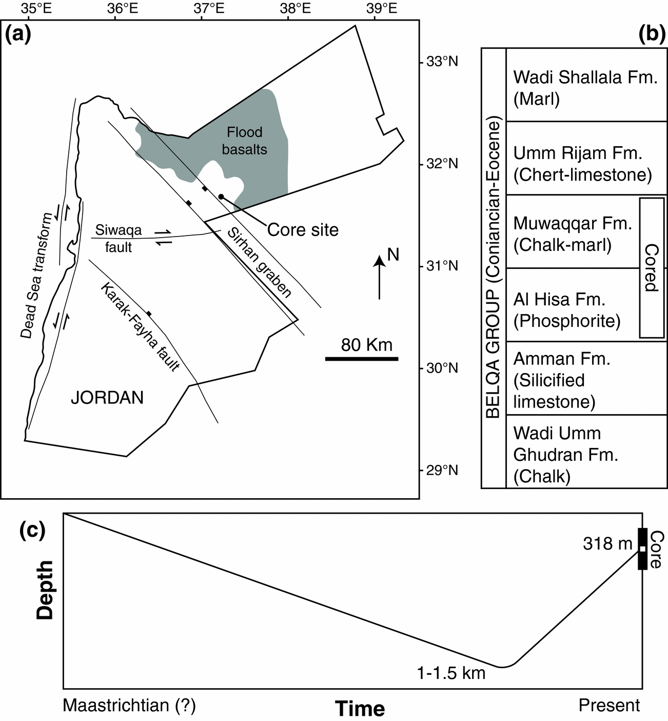
Figure 2. (a) Location of the core site. Flood basalts and major faults from Beydoun, Futyan & Jawzi (Reference Beydoun, Futyan and Jawzi1994), Ali Hussein et al. (Reference Ali Hussein, Alqudah, Podlaha, van den Boorn, Kolonic and Mutterlose2014 b) and Lüning & Kuss (Reference Lüning, Kuss, Marlow, Kendall and Yose2014). (b) Simplified stratigraphy of the Belqa Group, after Powell & Moh'd (Reference Powell and Moh'd2011), containing the cored interval. The cone-in-cone layer is within the Muwaqqar Formation. (c) Schematic burial history curve for the cone-in-cone sample studied.
The Cretaceous–Paleogene strata were deposited in the Sirhan Basin upon NW–SE-striking active normal faults (Abu-Jaber, Kimberley & Cavaroc, Reference Abu-Jaber, Kimberley and Cavaroc1989; Beydoun, Futyan & Jawzi, Reference Beydoun, Futyan and Jawzi1994). The core site is on the NE margin of the Sirhan graben system, in the footwall of a major graben-bounding normal fault (Fig. 2). Regional-scale tectonism during the Late Cretaceous was dominated by horizontal shortening and arch formation associated with the closure of the Tethys Ocean (Eyal & Reches, Reference Eyal and Reches1983; Abu-Jaber, Kimberley & Cavaroc, Reference Abu-Jaber, Kimberley and Cavaroc1989). Local extension from normal-fault motion in the Sirhan Basin accommodated sedimentary basin-fill and resulted in growth faulting and reworking of sediments (Alqudah et al. Reference Alqudah, Ali Hussein, Podlaha, van den Boorn, Kolonic and Mutterlose2014).
Cone-in-cone calcite is present within cores drilled throughout the Sirhan Basin (Ali Hussein et al. Reference Ali Hussein, Alqudah, Podlaha, van den Boorn, Kolonic and Mutterlose2014 b). However, cone-in-cone intervals are rare within cores; no more than three to four have been observed within any single core that penetrates the entire Muwaqqar Formation, which is typically at least 200 m thick. Cores, outcrops and mine exposures of the Belqa Group throughout northern Jordan contain abundant nodular carbonates (e.g. Abed & Amireh, Reference Abed and Amireh1983; Abed & Al-Agha, Reference Abed and Al-Agha1989; Pufahl et al. Reference Pufahl, Grimm, Abed and Sadaqah2003), but to our knowledge the core descriptions of Ali Hussein et al. (Reference Ali Hussein, Alqudah, Podlaha, van den Boorn, Kolonic and Mutterlose2014 b) are the first identification of cone-in-cone in the Belqa Group.
The core interval described here (Fig. 3) was recovered from a depth of 318 m below land surface. Regional geologic considerations and low thermal maturity of the Muwaqqar Formation suggest a moderately deeper burial, up to 1.5 km, preceding exhumation to the current depth. Assuming a typical geothermal gradient, this estimated maximum depth would correspond to a maximum temperature near 70 °C. Prograde burial and exhumation of the rocks is consistent with the southerly advance of Alpine shortening (Abu-Jaber, Kimberley & Cavaroc, Reference Abu-Jaber, Kimberley and Cavaroc1989).

Figure 3. Cone-in-cone structure from the Muwaqqar Formation, Jordan. (a) Core photo. (b) Thin section scan. White dashed lines mark sub-vertical fractures, roughly 100 μm wide. Layer-parallel bands are more transparent at this scale because they contain less host sediment and more calcite. Locations of petrographic images in Figures 6, 7, 9 and 13 indicated. Locations of Figures 5 and 10 are approximate; those figures were made from an accompanying SEM-polished thin section. Black dashed line shows transect across which horizontal scanlines were drawn (see Fig. 8).
The approximated maximum temperatures might have been reached amid shallower burial and hydrothermal fluid circulation. However, there is no evidence for hydrothermal activity aside from regional flood basalts (Bender, Reference Bender1974; Beydoun, Futyan & Jawzi, Reference Beydoun, Futyan and Jawzi1994). No basalt was intersected by the core, and the closest basalt in outcrop is c. 20 km to the east (Fig. 2).
3. Methods
Cone-in-cone was observed in core samples and in thin section. Thin sections include standard petrographic sections and sections polished for a scanning electron microscope (SEM). The SEM is an FEI Quanta 650 field-emission gun with cathodoluminescence (CL) and energy-dispersive X-ray spectroscopy (EDS) detectors. All SEM operations were performed at 20 kV. EDS spectra were collected at 10 mm working distance. Qualitative EDS maps are false-coloured for calcium, magnesium and silicon. The CL mirror geometry required a minimum working distance of ~18 mm, which was used. CL images use a large spot size and slow scan rate (6–18 h per frame; 0.003–0.01 s per pixel) to minimize streaking from persistent luminescence of carbonates.
Grain-size measurements were made from scaled optical and SEM photomicrographs. Variations in the abundances of rock constituents were quantified by measurement along lines of observation drawn parallel to bedding.
4. Sample description
The cone-in-cone sample on which this study is focused is present within a biosiliceous mudstone, c. 50 cm thick. The host rock contains abundant dolomite rhombohedra (hereafter, rhombs; Fig. 4) in a siliceous matrix. The matrix consists of amorphous organic matter and microgranular silica, likely having a biogenic origin, based on local radiolaria and bedded cherts elsewhere in the core. Foraminifera tests are also present but rare. Rhombs are 61 ± 21 μm in their longest dimension. Rhombs have irregular boundaries that might have resulted from reworking, but it is not clear whether they are detrital or authigenic. Rhombs are zoned in CL (Fig. 5). The zonation is typically concentric, often including a dimly luminescent core and brighter but variable rim. Rhombs compose 44 ± 10% of the host rock and 8.3 ± 6.4% of the cone-in-cone and, as described below, the distribution of rhombs varies proportionally with that of the siliceous matrix.

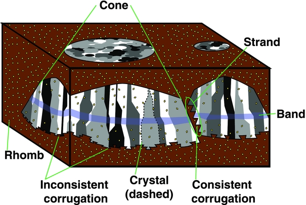
Figure 4. Schematic of cone-in-cone, including terms used in this study. Crystals are variously shaded to resemble the extinction patterns seen using cross-polarized light. Crystals are commonly demarcated by thinner host-rock strands than the one illustrated; these smaller strands are omitted for clarity. Note spatial density of rhombs within cones is proportional to the amount of host material in the cones, and therefore is lowest within the band (cf. Fig. 7).
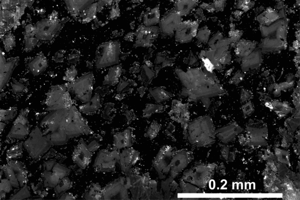
Figure 5. SEM-CL image of dolomite rhombs within host-rock strand. See Figure 3 for approximate location. Note most dolomite rhombs have concentric zoning. Rough edges are likely an artefact of polishing, given the highly luminescent polishing grit entrained within the matrix and around the rhombs.
The cone-in-cone interval is c. 7 cm thick (Fig. 3). The upper boundary of the cone-in-cone is gradational; the lower boundary is discrete and layer-parallel. The gradational upper boundary is composed of tiny calcite lenses (lengths on the order of 10 μm) sparsely distributed throughout the host rock. Moving downward, the calcite proportion increases relative to that of the host rock. The calcite bodies comprise multiple cones, which are demarcated by strands whose composition is identical to that of the rock layer that hosts the cone-in-cone (i.e. siliceous matrix with abundant rhombs). Based on their composition these areas between cones are here referred to as host-rock strands. Central to the later discussion will be the origin of these strands, including whether they comprise remobilized host sediment.
Cones are mostly composed of calcite, with subsidiary dolomite. Cone apices almost uniformly point upward. Rare downward-pointing cones are present underneath flat-lying strands of host rock near the top gradational boundary. Larger cones are composed of smaller cones (Figs 3, 6). Macroscopic cones are typically separated from one another by host-rock strands of mm-scale thickness; microscopic cones, by host-rock strands of μm-scale thickness. The thinnest host-rock strands are thinner than rhombs and generally contain no dolomite (Fig. 6c). The overall geometry of the cone-in-cone body is unclear because of the limited sampling of the core. However, the planar lower surface and gradational upper surface reflect the boundaries of small lenticular calcite bodies near the top of the cone-in-cone interval (Fig. 6), having discernible cones at their base and diffuse tops. These diffuse tops may be composed of cones too small to detect at the resolution of our microscopes and polishing techniques.

Figure 6. Cone-in-cone and host-rock strands. See Figure 3 for locations. (a) Plane-polarized light image of cone-in-cone with regions of sub-microscopic calcite crystals. (b) Interpretation of (a). The sub-microscopic calcite crystals near the top of the field of view are likely finer-scale cones, on the basis of intervening host-rock strands showing similar orientations to those in resolvable cone-in-cone. Lower, the isolated calcite bodies are composed in part of resolvable cones, yet tend to extend laterally into disc shapes (arrowed). (c) Host-rock strand among calcite cones; note dolomite rhombs and foraminifera test (arrowed). (d) Map-view of sample showing discontinuous, annular form of host-rock strands.
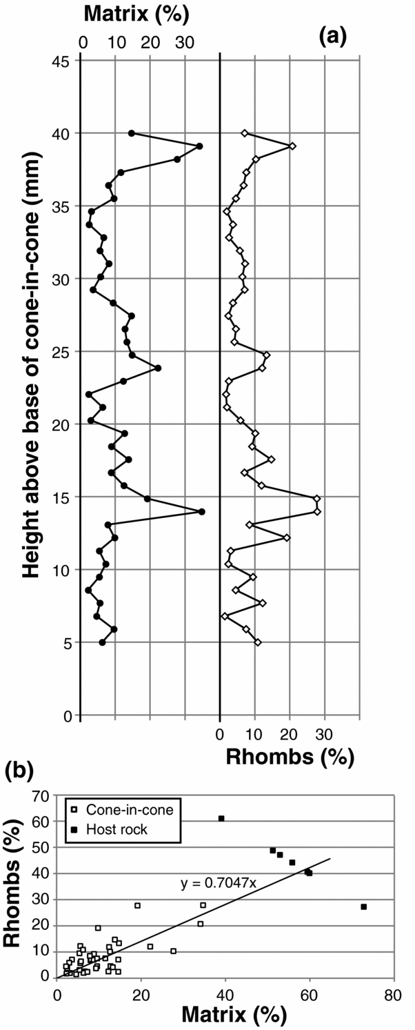
Lower in the sample, layer-parallel bands transect cones (Fig. 3). The bands are seen optically to be regions that vary in calcite:host-rock ratio. Rhomb density (number per unit area) is proportional to the host-rock fraction (Figs 7, 8), and so, within the calcite-rich bands, both rhombs and matrix are less abundant. The rhomb:matrix ratio remains roughly constant throughout the sample, including within the host rock (Fig. 8b).

Figure 7. Petrographic images of cone-in-cone. See locations in Figure 3. (a) Microscopic cones (transparent) separated by host-rock strands (opaque). Plane-polarized light. (b) Same as (a), cross-polarized light. Note crystals at coarser scale than cones. Dispersed white spots are dolomite rhombs. (c) Microscopic cones forming a macroscopic cone separated from neighbouring crystals by thicker host-rock strands. Plane-polarized light. (d) Same as (c), cross-polarized light. In (b) and (d), note rhomb density coincides spatially with host-rock strand density, both being lowest within the band.

Figure 8. Abundance of rhombs and siliceous matrix, within cone-in-cone and host rock. (a) Variation across bands within cone-in-cone; see approximate location of transect in Figure 3. (b) Cross-plot of the same data in (a) including host-rock measurements. Best-fit linear extrapolation from cone-in-cone measurements intersects the host-rock measurements, meaning that the rhomb:matrix ratio does not systematically vary from ~0.7, throughout the core sample.
The bands show minor offset across macroscopic host-rock strands, but it is unclear whether this offset is structural, resulting from shear along the intervening host-rock strand, or whether the bands formed with slight stratigraphic offset. Both interpretations assume that the bands represent layers of contemporaneously precipitated calcite (Fig. 1), whether forming a slight mismatch across strands during precipitation (primary cone-in-cone) or offset afterward (secondary cone-in-cone).
The calcite composing the cone-in-cone is composed of optically continuous crystals (Fig. 7). The boundaries between these crystals either lie along host-rock strands or are roughly vertical and smooth, with no space between neighbouring crystals. Thus the cone-in-cone sample can generally be regarded as fibrous, its crystals being horizontally thin and vertically long, although some crystals are limited in height and so better qualify as equant. Here we refer to optically continuous parts of the cone-in-cone as crystals, which can be identified by uniform extinction in cross-polarized light (Fig. 7). The size of crystals varies throughout the cone-in-cone but is mostly consistent laterally. Horizontal widths range from roughly 100 μm to a few mm; vertical lengths reach up to 3 cm. Crystal size generally coarsens toward the bottom, but calcite-rich, strand-poor bands are marked by smaller and more fibrous crystals.
Crystals are generally, though not exclusively, larger than the smallest cones resolvable using a light microscope; larger-scale cones are larger than crystals. Consequently, some host-rock strands are entirely enveloped within individual calcite crystals (Fig. 7), whereas other strands, generally larger ones, demarcate the boundaries between neighbouring crystals.
Host-rock strands demarcating cones have smooth undersides and corrugated (Woodland, Reference Woodland1964) upper sides (Fig. 9). Throughout the sample, strands dip near 55° from horizontal, either to the left or right in thin section. Corrugations mark the intersections of clay rings (Gresley, Reference Gresley1894; Franks, Reference Franks1969) with the thin section, based on the annular geometry of host-rock strands in map view (Fig. 6d). Each corrugation in the upper side of the strand consists of one edge at low angle-to-bedding and a second edge having a steep dip. These two sets of edges alternate, producing a consistently stepping corrugation (consistent corrugation) to the upper surface of the strand.

Figure 9. Corrugations. See locations in Figure 3. (a) Plane-polarized light image of host-rock strand having consistently corrugated upper surface and smooth lower surface. (b) Interpretation of growth sequence of (a). Arbitrarily coloured/shaded lines follow the inconsistently corrugated, downward-growing bottom surface of the cone-in-cone structure. Growth lines in left-side cone labelled sequentially. Lower cones halt the growth of upper cones; see text for discussion. (c) Cones at the lower surface of cone-in-cone. (d) Interpretation of (c), highlighting inconsistent corrugation along the bottom surface and consistent corrugation of the smaller-scale cones that make up the larger cones.
Cones generally either terminate within the cone-in-cone at a dipping host-rock strand, or at the bottom of the cone-in-cone interval. The bottom of the interval is macroscopically flat (Fig. 3) but microscopically corrugated (Fig. 9c). The corrugation at the bottom of the cone-in-cone is referred to here as inconsistent; flat-lying micro-scale surfaces are separated by steep surfaces dipping one way or the other, with varying lengths, and the sequence is irregular.
The sample contains rare sub-vertical opening-mode fractures, i.e. fractures lacking shear offset (Figs 3, 9). Each opening-mode fracture is entirely filled by inclusion-free calcite and has a width on the order of 100 μm. Fracture calcite is in optical continuity with cone calcite. These fractures appear to cross-cut the cones, commonly lying along host-rock strands for some distance between vertical cuts through calcite (Fig. 3). The fractures are therefore interpreted to post-date the cone-in-cone.
Minor dolomite is present within the calcite cones (Fig. 10). Dolomite has an equant to fibrous habit similar to that of the calcite. Dolomite forms optically continuous crystals similar to those of calcite in that their lateral boundaries are generally vertical. In contrast to calcite crystals, dolomite crystals are smaller; most are less than 300 μm in their longest dimension, which is usually vertical. In contrast to the dolomite rhombs described above, the dolomite crystals are bigger; recall that rhombs are near 60 μm in their longest dimension.

Figure 10. SEM images of cone-in-cone. See Figure 3 for approximate location. (a) Backscattered electron image showing distribution of dolomite crystals. Ca, calcite; Dol, dolomite. (b) CL image. Dolomite is zoned. R, rhomb; DC, dolomite crystal (some include rhombs). Rhombs have the characteristic size and concentric zoning pattern of host-rock rhombs (Fig. 5); matrix mud is included around rhombs. Dolomite crystals that contain rhombs also have non-concentrically zoned dolomite extending downward from the rhomb. (c) EDS image. HR, host-rock strand. (d) superposition of (b) and (c) to highlight the zoning within dolomite and relationships between dolomite and calcite. Dolomite crystals share vertical boundaries with fibrous calcite. Where rhombs are overgrown by authigenic dolomite in a crystal, the two are in optical continuity (inset – yellow lines mark optically continuous crystals), and rhombs are at the top of the crystal. This suggests that the overgrowths grew downward from the rhombs, terminating against calcite fibres as the cone-in-cone grew. Dolomite crystals without rhombs may overgrow rhombs that are out of the thin-section plane, or they may be purely authigenic crystals. (e) SEM-CL-EDS image, combined as in (d), of another example of a dolomite crystal including a concentrically zoned rhomb at its upper end.
Cathodoluminescence of dolomite crystals shows that crystals commonly include one concentrically zoned dolomite rhomb at the top of the crystal (Fig. 10). Dolomite crystals terminate downward upon surfaces parallel to variably luminescent zones within the dolomite. These lower terminations of dolomite crystals lie against calcite crystals; in contrast, essentially all concentrically zoned dolomite rhombs within the cone-in-cone are surrounded by at least trace amounts of siliceous matrix (Fig. 10e).
5. Interpretation
5.a. Direction of growth
In cone-in-cone samples that are symmetrical about a medial plane (i.e. nodules or layer-parallel veins) the apices generally point inward, and the bases lie at the sediment:nodule interface (Cole, Reference Cole1893; Gresley, Reference Gresley1894; Woodland, Reference Woodland1964; Marshall, Reference Marshall1982). In those studies it was therefore interpreted that the cones grew from the apices toward the bases. As with the growth of the less-enigmatic parallel-fibrous calcite veins, this interpretation is based on the assumption that calcite is added to the growing vein at the sediment:vein interface, without any cracking (Bons, Elburg & Gomez-Rivas, Reference Bons, Elburg and Gomez-Rivas2012).
If the cone-in-cone is primary, then the asymmetry of the cone-in-cone structure described here is consistent with downward growth, from the apices toward the bases. If secondary, perhaps the direction of calcite growth cannot be inferred, although the gradational top and discrete bottom of the structure, as well as the asymmetry of the banding, corroborate a unidirectional growth. Furthermore, it is simplest to assume that the basal surface of the cone-in-cone structure remained relatively planar throughout growth, though possibly with minor offset across host-rock strands, as discussed below. This interpretation is supported by the roughly layer-parallel geometry of the bands, which, when they precipitated, would have formed the coeval basal growth surface of the calcite structure.
5.b. Origin of rhombs and their inclusion into the calcite
Dolomite rhombs in the host rock are either authigenic or detrital, and if detrital, their angular form indicates that they have not been transported far. If the rhombs are detrital, they pre-date the cone-in-cone; if they are authigenic, they might pre-, syn-, or post-date the cone-in-cone structure.
We interpret that the rhombs within the cone-in-cone are the same as the rhombs within the host rock. This interpretation is based on (i) the equal size of the rhombs within the cone-in-cone and host rock; (ii) the similar zoning pattern (Figs 5, 10); (iii) the constant relative abundance of rhombs and matrix mud within the host rock throughout the cone-in-cone (Fig. 8); and (iv) the presence of matrix mud included around the margins of the rhombs within the cone-in-cone (Fig. 10).
At least three possibilities exist to explain the inclusion of the host-rock rhombs into the cone-in-cone (Fig. 11). First, the inclusion may have been primary; that is, the cone-in-cone may have grown around the rhombs. Second, the rhombs may have been injected into the cone-in-cone along fractures. Third, rhombs may have crystallized in place after the cone-in-cone formed, regardless of whether the host material was emplaced primarily or injected along fractures. The ambiguity of the final rhomb arrangement stymies interpretation of the origin of cone-in-cone. Further evidence is therefore necessary in order to eliminate any of these three possibilities.

Figure 11. Timing hypotheses for (top) calcite, cones and dolomite rhombs; (bottom) dolomite crystals amid calcite. At top, cone-in-cone may be primary, originating with the calcite precipitation, or secondary, post-dating the calcite. Dolomite rhombs may pre- or post-date calcite (former are detrital or early-authigenic; latter are late-authigenic). The final arrangement is identical in each case. At bottom, stripes represent calcite crystals, which are vertical or follow host-rock strands (Figs 7, 10). If dolomite crystals post-date calcite, then they grew by replacing calcite, and so should extend outward from rhombs in all directions, or at least extend upward as easily as downward. The observed arrangement (Fig. 10) shows dolomite crystals extending downward from rhombs and not upward. This suggests that the rhombs were already present when the calcite formed, and that the dolomite crystals co-precipitated with calcite.
5.c. Timing of dolomite crystals
Two possible explanations are considered here for the distribution of dolomite crystals that include rhombs within the cone-in-cone calcite (Fig. 11). First, the dolomite crystals may be overgrowths of rhombs, which grew as the cone-in-cone grew. Second, the dolomite crystals might have nucleated from rhombs after the cone-in-cone formed and grown by replacing calcite. In that case, the dolomite crystals post-date the cone-in-cone.
The second of these explanations is much less likely than the first. If the cone-in-cone was already formed, and entirely composed of calcite, by the time dolomitization commenced, then there would presumably be no preferred direction in which the dolomitization should proceed. It could be argued that the host-rock strands and crystallographic boundaries would serve as barriers to dolomitization, although dolomite rhombs that replace calcite commonly transgress multiple original grains (e.g. Moss & Tucker, Reference Moss and Tucker1995; Merino & Canals, Reference Merino and Canals2011). But even if crystal boundaries did halt dolomitization, there is no apparent reason why the dolomitization should proceed preferentially downward from the rhombs – in the direction in which the cone-in-cone presumably grew – and not upward (Fig. 10).
Also, given the single dolomite-nucleation site represented by an optically continuous rhomb, it might be expected that dolomite would pseudomorphically replace the calcite crystals, such that replacement dolomite would have optical continuity with the calcite crystals (Tucker & Wright, Reference Tucker and Wright1990), but this is not the case.
The observation that the dolomite crystals extend downward from an optically continuous rhomb is better explained by the first hypothesis: that dolomite overgrew rhombs while the cone-in-cone was growing. Figure 12 is an interpretation of this process, consistent with the observations. The cone-in-cone structure grew by adding calcite and dolomite to the basal contact with the host rock, thus from the apices toward the bases as discussed above. In principle the ions composing these minerals should have been delivered to the basal surface within an aqueous fluid, whether those ions were replenished by fluid advection or diffused through a static fluid. As the cones grew, the host material – silicate mud and dolomite rhombs – was included between the cones. Locally the dolomite rhombs would have been exposed to the basal precipitation surface. Where the rhombs were thus exposed it was more thermodynamically favourable for the dissolved ions to precipitate as dolomite. That is, both dolomite and calcite crystals precipitated into the pore fluid, with the mineral determined by the exposed substrate.
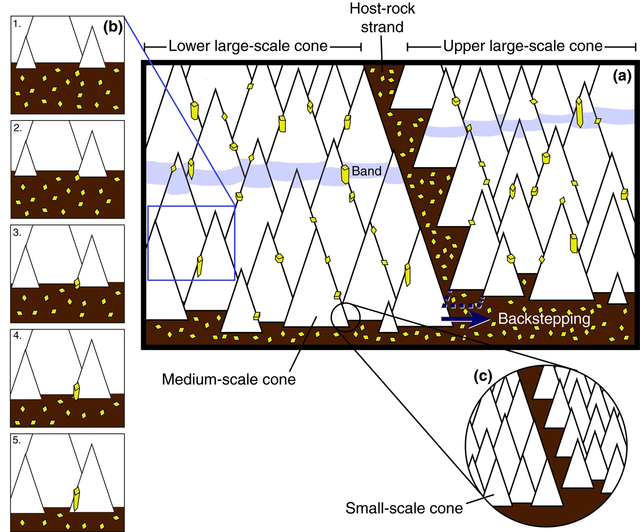
Figure 12. Schematic of growth of cone-in-cone. (a) Two large-scale cones meet at a host-rock strand with consistently corrugated upper side, formed by the halting of the upper cone against the lower cone. This halting happens because there is not enough room for medium-scale cones within the upper cone to grow against the lower cone. The dashed blue line represents space which cannot be filled by calcite cones; consequently the next row of medium-scale cones within the upper large-scale cone will ‘backstep’ to the right. The vertical separation defining ‘upper’ and ‘lower’ can be seen in the offset of both the band and the lower large-scale conic surfaces. These bottom surfaces are inconsistently corrugated rows of medium-scale cones. Dolomite rhombs and overgrowths drawn as in Figure 11. The band marks the previous basal surface of the structure. (b) Ensconcement of dolomite rhomb and development of overgrowth. As calcite cones grow downward (time-steps 1 to 5), host-rock rhombs are mostly pressed downward and out of the frame; one rhomb is entrained in the lattice. A dolomite overgrowth grows downward from the rhomb, blocking the growing calcite. At time-step 5, the dolomite crystal has formed a lower euhedral termination and neighbouring calcite crystals continue growing downward in its place. (c) Small-scale cones illustrate how the corrugation of cone-bounding host-rock strands is analogous at smaller scales (see Fig. 13).
Because dolomite crystals are relatively short, terminating downward against calcite crystals within less than 1 mm, it appears that calcite generally precipitated faster than dolomite. The substrate effect was soon overcome by the faster growth of calcite. Perhaps dolomite growth was limited by the supply of Mg2+ in solution. Alternatively, the rate of dolomite crystal growth may have been slower because the host-rock dolomite rhombs already had euhedral faces upon incorporation into the cone-in-cone. The calcite, in contrast, may have precipitated upon fossils or spontaneously nucleated in micro-pores, but either way appears to have grown from multiple anhedral nuclei throughout the growth of the cone-in-cone. Thus the calcite may have grown faster because growth is generally faster on atomically rough (anhedral) surfaces (e.g. De Yoreo & Vekilov, Reference De Yoreo and Vekilov2003).
Some dolomite crystals do not include rhombs. This could be an artefact of the thin-section plane; the crystal is taller and presumably, in many cases, wider than the rhomb, so the crystal has a greater likelihood of intersecting the thin-section plane than does the rhomb within it. Overgrowths may likewise not all extend purely vertically but rather out of the vertical thin-section plane. Alternatively, there may be dolomite in the cone-in-cone that nucleated spontaneously rather than upon rhombs. Regardless, the planar, vertical boundaries of such crystals suggest co-precipitation with calcite into the pore fluid rather than replacement of calcite.
If it is accepted that the dolomite crystals that are in optical continuity with rhombs are indeed overgrowths of those rhombs, then it follows that the inclusion of the rhombs into the cone-in-cone was primary. If the dolomite crystals are overgrowths of rhombs and share planar, vertical boundaries with the calcite crystals, then the rhombs must have been in place as the calcite grew. Therefore the host-rock strands, which contain the rhombs over which the dolomite crystals grew, could not have been injected into the cone-in-cone after the calcite precipitated; rather, the calcite grew in its conical form, incorporating strands of host rock as it grew. That is, the cone-in-cone is primary in origin.
6. Discussion
6.a. A kinematic model for primary growth of cone-in-cone
The textural evidence presented above demonstrates the primary origin of the present sample. We believe that the primary-origin interpretation applies to cone-in-cone in general, because the morphology of the host-rock strands in the present sample – a smooth lower side and a consistently corrugated upper side – is characteristic of cone-in-cone in general.
Previous studies have noted host-rock inclusions within layer-parallel fibrous veins and interpreted that the inclusions were incorporated within the veins during mineral precipitation and not afterward. In examples provided by Hilgers & Urai (Reference Hilgers and Urai2005) and Cobbold et al. (Reference Cobbold, Zanella, Rodrigues and Løseth2013), the host-rock inclusions form triangular trails in cross-section, potentially reflecting a conical fibrous structure in three dimensions. In those examples, the edges of host-rock inclusions fit together like puzzle pieces when translated along the fibres separating them. This fact supports the interpretation of primary incorporation into the veins as opposed to later injection by fracturing, during which the included host material would likely have been rotated or distorted.
Host-rock strands within the present sample are not so easily reassembled to their original geometry, owing to the minuscule widths of many host-rock strands, particularly the thin matrix inclusions interspersed among relatively coarse rhombs (Figs 6, 7, 9, 10b). Lacking such visually reconstructible geometry for corrugated host-rock strands, which are characteristic of classical cone-in-cone, we propose the following interpretation for how corrugations develop.
Inconsistent corrugation forms as rows of cones grow at the bottom surface of the structure. These cones are not perfectly side-by-side and so the bottom surface is rough; this roughness is inconsistent corrugation. Similarly, consistent corrugation forms as cones grow downward against the tilted surface of an underlying cone (Fig. 12). That the lower cone halts the growth of the upper cone is evident from the full conic shapes of cones that reach the bottom surface versus the incomplete cones of those up-section. These incomplete cones can be considered to correspond to the conic scales of Gresley (Reference Gresley1894).
If the cone-in-cone grew downward, then where neighbouring cones meet, that cone which extends even slightly more down-section will halt the growth of the more up-section cone. Because macroscopic cones grow by the addition of microscopic cones forming in inconsistently corrugated rows, the halting of a macroscopic cone is achieved by the ‘backstepping’ of these rows of microscopic cones (Fig. 12). The lower of these two macroscopic cones will continue to grow downward, by the addition of another row of microscopic cones in an uninterrupted conical array, whereas the upper macroscopic cone will step backward from the lower cone. This stepping is represented by the shortening of each successive row by one or more discrete microscopic cones, because there is insufficient space for microscopic cones to grow. The uninterrupted upper surface of the lower (macroscopic) cone forms the smooth underside of the host-rock strand. The progressive backstepping of the upper (macroscopic) cone produces the consistently corrugated upper side of the host-rock strand. Therefore the growth of cones against the horizontal basal surface produces inconsistent corrugation, but the growth of cones against the tilted top of an underlying cone produces consistent corrugation (Fig. 13).

Figure 13. Reconstruction of two interfering, macroscopic cones (Fig. 3). (a) Plane-polarized light image showing the intersection of two large-scale cones. (b–e) Interpretation and reconstruction of (a); (e) shows final state photographed in (a). Host-rock rhombs are pushed downward from growing cones or ensconced within the cone calcite. The higher large-scale cone on right cannot grow laterally into the space occupied by the lower cone on left. The left-side cone, being lower, therefore blocks the growth of the right-side cone, and the boundary between them moves to the right as the cones grow downward. The blocking of the right-side cone produces a consistently corrugated upper surface to the host-rock strand demarcating the cones. The smooth lower surface of the strand defines the top of the left-side cone. The flat bottom-surface of the cone-in-cone is inconsistently corrugated throughout the growth process. Note consistent corrugation of strands between smaller-scale cones, suggesting that the same blocking process occurs at smaller scales.
The physical mechanism for conical calcite growth remains unexplained, as do the factors controlling the width of host-rock strands. The basis of this conical-interference growth model is the combined simplicity of its rules and thorough accounting for the salient characteristics of cone-in-cone. Below we speculate about the physical processes involved.
6.b. Previous arguments for primary cone-in-cone
The interpretation that cone-in-cone is primary is supported by several other, arguably weaker, lines of evidence, many of which have been presented by previous workers. For example, cone-in-cone is said to have a primary origin because the cone-in-cone expands the detrital framework of the host sediment (Franks, Reference Franks1969). This expansion is apparent in Jordan from the sparse distribution of rhombs (Fig. 7), as well as rare foraminifera tests (Fig. 6c), in proportion to the matrix included within the calcite cones (Fig. 8). The secondary cone-in-cone hypothesis suggests that the framework grains were injected into fractures within the calcite after the calcite was precipitated. It is difficult to envision how such large, rigid particles could have been injected into the calcite along ‘fractures’ as narrow as the thinnest host-rock strands. Such an injection would have preferentially emplaced matrix mud into the narrowest fractures, resulting in a lower abundance of rigid grains within the host-rock strands, relative to that abundance in the host rock outside the cone-in-cone. But the abundance of rhombs is equal in the host rock and the strands. It is thus more reasonable to interpret the strands as primary inclusions of the host material than as fractures. (It may be that the rhombs post-date this hypothetical host-sediment injection (Fig. 11) and that we are incorrect in our interpretation of the dolomitization, but the foraminifera certainly pre-date the cone-in-cone and would therefore have to have been injected.)
The separation of calcite crystals by host-rock strands is likewise difficult to attribute to fracturing. The extinction angles of calcite crystals can vary markedly across even the most inconspicuous host-rock strands (Fig. 7). If fracturing created significant mismatch of crystallographic axes within an originally optically continuous calcite body, then we would expect to see evidence of rotation of the calcite blocks on either side of the fracture, such as brecciation or progressive rotation of axes with increasing distance from the fractures. There is neither such evidence present, nor is there evidence of crystal strain, as from non-uniform extinction. It is conceivable that a hypothetical fracture – invoked by the secondary cone-in-cone hypothesis – injecting host-material between pre-existing crystals could have propagated along a weakness represented by the crystallographic boundary, but in that case the conical boundaries would be primary. Instead, the simplest explanation for the bounding of crystals by host-rock strands was given by Richardson (Reference Richardson, Lang, Spath and Richardson1923), who observed that calcite fibres terminate against host-rock strands, rather than being cut by the strands. The crystals (or fibres, in the case of Richardson, Reference Richardson, Lang, Spath and Richardson1923) were originally and always separated by the host-rock strand. The crystals formed on either side of the host-rock strand, which was included between the cones as the calcite precipitated.
Nonetheless, thicker strands are more likely to juxtapose misoriented crystals. As such, thin strands can be included within relatively large, optically continuous calcite crystals (Fig. 7). Presumably, the smallest-scale cones template crystallographically upon extant cones up-section and nonetheless ensconce host material in between. It is interesting that the cones take on a scale-free aspect (Figs 6, 9, 12c) despite a strand-size dependence of crystallographic continuity. This observation supports the view, previously stated, that calcite crystallography is likely unimportant for conic pattern formation (Tarr, Reference Tarr1922; Woodland, Reference Woodland1964; Franks, Reference Franks1969). That is, strands can be included between or within crystals, with no difference in the morphology of the strand.
Maher, Ogata & Braathen (Reference Maher, Ogata and Braathen2016) pointed out that the cone-bounding host-rock strands generally dip at a steeper angle than would be expected for thrust-displacement faults, according to Andersonian faulting theory. Indeed, cone-demarcating strands within the present sample, and nearly all documented examples, dip more steeply than 45°, for which we would expect a maximum compressive stress that is vertical, and a normal sense of displacement.
A final argument is that the shapes of the host-rock strands toward the top of the sample (Fig. 6a, c) are difficult to interpret as fractures. The strands have a straight edge that overlies the tilted upper surface of underlying cones, and thus have a roughly triangular overall shape. If such a strand is a fracture, it would be expected to have a roughly parallel, albeit possibly corrugated, opposite edge. It is simpler to interpret the fine-grained material in Figure 6 as the negative space between multiple separate cones. This interpretation is further supported by the horizontal disc-shapes of the smallest aggregates of cones within the strands (Fig. 6a, b). If the host-rock strands are fractures, then these discs within the strands appear to post-date the fractures; otherwise the discs should have been rotated somewhat from horizontal upon injection. But because these discs themselves are formed of cones, there must have been multiple calcite-precipitation and conical-fracturing events, presumably all while the sediment was plastic. On the other hand, if the cone-in-cone is primary, then all the calcite cones would have formed during a single, if protracted, phase of growth.
6.c. Formation mechanisms and depth of burial
If the present interpretation is correct, then the purported secondary mechanisms which injected host material and formed the cones, mentioned in the Introduction, are not necessary to the formation of cone-in-cone. Therefore these mechanisms should not be interpreted to have occurred in rocks bearing cone-in-cone without further evidence.
Furthermore, the apparent vertical displacement of the host material in our core sample by the cone-in-cone implies that the vertical compressive effect of the overburden was counterbalanced during calcite precipitation, whether by static fluid overpressure (Sellés-Martínez, Reference Sellés-Martínez1996; Hillier & Cosgrove, Reference Hillier and Cosgrove2002), seepage forces (Cobbold & Rodrigues, Reference Cobbold and Rodrigues2007; Maher, Ogata & Braathen, Reference Maher, Ogata and Braathen2016) or the force of crystallization (Richardson, Reference Richardson, Lang, Spath and Richardson1923; Franks, Reference Franks1969). Stress and fluid pressure conditions favouring cone-in-cone formation could have been present early, during shallow burial and thus low overburden stress; during deep burial and strong fluid overpressure; or late, during exhumation. That previous geochemical studies have led to inferred burial depths ranging from tens to thousands of metres, as mentioned in the Introduction, suggests that cone-in-cone does indeed form under a variety of burial conditions in nature.
Previous studies invoked the unconsolidated nature of the sediment as being important to cone-in-cone formation, based on the compacted appearance of clay inclusions (Woodland, Reference Woodland1964), contortion of the enclosing material (Franks, Reference Franks1969) and cone-in-cone being systematically cross-cut by brittle structures (Maher, Ogata & Braathen, Reference Maher, Ogata and Braathen2016). Within the present sample, the narrowest host-rock strands are narrower than the rhomb widths and contain no dolomite. Therefore we infer that the rupture of host material, along surfaces now enveloping calcite, occurred only within the matrix and did not cleave rhombs. This pattern would be expected if the rhombs and foraminifera were relatively rigid and the matrix poorly consolidated.
However, poor bonding between microscopic silicate grains and organic material in the matrix, relative to the bonds within carbonate mineral lattices, could maintain such a mechanical contrast even down to metamorphic depths. Moreover, the constancy of the rhomb:matrix ratio, throughout the cone-in-cone and host rock, suggests that the growth of calcite did not deform the host material via grain-boundary sliding. If the matrix had behaved as a fluid during cone-in-cone formation, such that pressure exerted upon the rigid rhombs could displace them with respect to the matrix, then we might expect to see a greater proportion of matrix within the strands demarcating the cones, and a corresponding greater proportion of rhombs surrounding the cone-in-cone. We conclude that, although the matrix was weaker than the rhombs, it was nonetheless sufficiently consolidated as to be spatially coupled with the framework grains during displacive growth of calcite. An effectively solid matrix is also consistent with the vein-like geometry of many cone-in-cone samples (Cobbold et al. Reference Cobbold, Zanella, Rodrigues and Løseth2013; Le Breton, Cobbold & Zanella, Reference Le Breton, Cobbold and Zanella2013; Parnell et al. Reference Parnell, Blamey, Costanzo, Feely and Boyce2013; Maher, Ogata & Braathen, Reference Maher, Ogata and Braathen2016).
We still lack a satisfactory explanation for the conic shape. However, the interpretation that cone-in-cone is an amalgamation of crystalline bodies, separated since precipitation by host-rock strands, suggests that that conic morphology develops as a result of the interfering, space-filling growth of those crystalline bodies, as conceptually illustrated in Figure 12. We speculate that the final conic pattern arises from either (i) the initial arrangement of the nucleation sites, which presumably are either pore spaces or carbonate fragments within some stratum, or (ii) the deformation of the host material as individual bodies grow, which could trigger new bodies to grow in the vicinity of extant ones. This latter process is akin to the notion that growing fractures may dynamically produce en échelon arrays (Olson & Pollard, Reference Olson and Pollard1991), with host-rock strands or septae intervening.
6.d. Secondary cone-in-cone, or overprinted deformation?
The present sample refutes other arguments in favour of secondary cone-in-cone. It has been argued that offset of growth bands along host-rock strands shows that shearing is involved in the formation of cone-in-cone (Tarr, Reference Tarr and Twinhofel1932; Kowal-Linka, Reference Kowal-Linka2010). The bottom surface of the present sample, which is interpreted as a surface of coeval precipitation, is uneven across the host-rock strand. No shearing needs to be invoked to explain this offset; the offset is primary to the assemblage of the structure. The lower part of the surface belongs to the lower cone; the upper cone grows downward against the lower cone, creating the corrugations along the intervening host-rock strand (Figs 12, 13).
Importantly, in other samples there may be superimposed shear between cones, as primary host-rock strands might serve as long-term surfaces of weakness within a rigid calcite body. Such weakness is consistent with the tendency for later fractures to propagate along host-rock strands (Figs 3, 9). But such superimposed deformation has nothing to do with the origin of cone-in-cone. The same argument holds for related structures within cone-in-cone samples that have been suggested as vital to its formation, including pressure-solution residues and slickensides within cone-bounding clay rings (Tarr, Reference Tarr and Twinhofel1932), and apparent shear fractures between cones (Durrance, Reference Durrance1965; Gilman & Metzger, Reference Gilman and Metzger1967), here interpreted as primary-growth corrugations. There is no evidence in the Jordan sample of pressure solution or any secondary, brittle deformation associated with the formation of the cones.
It is of course possible that different mechanisms may produce similar structures: that other cone-in-cone examples may have formed by secondary deformation, including recrystallization, of non-conical calcite (or aragonite) bodies. There is an interesting similarity between the dolomite crystals here and the ‘straightened rhombohedra’ of Aso, Gisbert & Garcés (Reference Aso, Gisbert and Garcés1992). That study noted cone-in-cone fibres that represent assemblages of rhombohedral calcite crystals. Those authors suggested that such fibres formed by alignment of rhombohedra into fibres from an organic gel parent-phase, with conical cracking as a by-product. Important differences between those fibres and the dolomite crystals investigated here include the latter sample having (i) commonly only a single rhombohedron in each crystal and (ii) abundant chemically and morphologically identical rhombohedra in the host rock. Still, the common observation of rhombohedra serving to align crystals composing cone-in-cone, mutatis mutandis, is compelling.
7. Conclusions
A cone-in-cone sample from Jordan includes all the distinguishing characteristics of the structure, including crystalline composition, horizontal attitude with vertical cones in a fine-grained sedimentary host, and cones demarcated by strands of fine-grained material. In this sample, the host rock contains abundant dolomite rhombohedra, in equal abundance outside the cone-in-cone and within the strands that demarcate the cones. The cones include dolomite crystals, which are interpreted to be overgrowths of dolomite rhombohedra and which appear to have formed during the growth of the cone-in-cone. These interpretations are based on the dolomite crystals’ (i) having optical continuity with the rhombohedra and not with neighbouring calcite fibres, (ii) having an equant-fibrous habit, like that of the calcite composing the cone-in-cone, and (iii) extending systematically downward from the rhombohedra, in the apparent direction of growth of the cone-in-cone. The rhombohedra were therefore in place as the cone-in-cone grew. This means that the cone-in-cone is a primary structure – that it incorporated host material and formed its conic shape as the calcite precipitated, and not afterward.
Consistent with this interpretation are: host-rock strands with non-parallel edges, suggesting the strands are not fractures; rigid grains (dolomite rhombohedra and foraminifera tests) ensconced in the calcite cones, suggesting the grains were not injected along narrow fractures; and mismatched crystallographic orientation of calcite crystals across host-rock strands, suggesting that the crystals grew independently and were never a single, continuous crystal. Previous studies ascribing the formation of cone-in-cone to shearing or fracturing commonly fail to make the case against superimposed deformation onto pre-existing cone-in-cone; the relatively pristine preservation of the Jordan sample shows that cone-in-cone can form without invoking a stage of deformation that follows the original precipitation.
Acknowledgements
This work has been funded by Shell International Exploration and Production B.V. We are grateful to M. Ali Hussein and M. Alqudah for pointing out the cone-in-cone sample to us, and for discussion of its form and origin. We thank J. Huggett, A. Dickson, S. van den Boorn, O. Podlaha, M. Gross, R. Pierpont and M. Claps for helpful discussion. We thank J. Wells for sample preparation and O. Green and N. Charnley for assistance with microscopes. We thank J. Marshall for an insightful review, H. Løseth and J. Hendry for helpful reviews of a previous version of the manuscript, and M. Allen for seeing the manuscript through the review process.
Declaration of interest
This work has been funded by Shell International Exploration and Production B.V.